


MODEL GFC 7000TA
CARBON DIOXIDE ANALYZER
Operation Manual
Also supports operation of:
GFC 7000T CO2 Analyzer
(when used in conjunction with GFC 7000T Addendum, PN 07273)
P/N M07272
DATE 06/04/13
TELEDYNE ELECTRONIC TECHNOLOGIES
Analytical Instruments
16830 Chestnut Street City of Industry, CA 91748
Telephone: (626) 934-1500 Fax: (626) 961-2538
Web: www.teledyne-ai.com
 Teledyne Analytical Instruments

Model GFC7000TA Carbon Dioxide Analyzer
Copyright © 2013 Teledyne Analytical Instruments
All Rights Reserved. No part of this manual may be reproduced, transmitted, transcribed, stored in a retrieval system, or translated into any other language or computer language in whole or in part, in any form or by any means, whether it be electronic, mechanical, magnetic, optical, manual, or otherwise, without the prior written consent of Teledyne Analytical Instruments, 16830 Chestnut Street, City of Industry, CA 91748.
Warranty
This equipment is sold subject to the mutual agreement that it is warranted by us free from defects of material and of construction, and that our liability shall be limited to replacing or repairing at our factory (without charge, except for transportation), or at customer plant at our option, any material or construction in which defects become apparent within one year from the date of shipment, except in cases where quotations or acknowledgements provide for a shorter period. Components manufactured by others bear the warranty of their manufacturer. This warranty does not cover defects caused by wear, accident, misuse, neglect or repairs other than those performed by Teledyne or an authorized service center. We assume no liability for direct or indirect damages of any kind and the purchaser by the acceptance of the equipment will assume all liability for any damage which may result from its use or misuse.
We reserve the right to employ any suitable material in the manufacture of our apparatus, and to make any alterations in the dimensions, shape or weight of any parts, in so far as such alterations do not adversely affect our warranty.
Important Notice
This instrument provides measurement readings to its user, and serves as a tool by which valuable data can be gathered. The information provided by the instrument may assist the user in eliminating potential hazards caused by his process; however, it is essential that all personnel involved in the use of the instrument or its interface be properly trained in the process being measured, as well as all instrumentation related to it.
The safety of personnel is ultimately the responsibility of those who control process conditions. While this instrument may be able to provide early warning of imminent danger, it has no control over process conditions, and it can be misused. In particular, any alarm or control systems installed must be tested and understood, both as to how they operate and as to how they can be defeated. Any safeguards required such as locks, labels, or redundancy, must be provided by the user or specifically requested of Teledyne at the time the order is placed.
Therefore, the purchaser must be aware of the hazardous process conditions. The purchaser is responsible for the training of personnel, for providing hazard warning methods and instrumentation per the appropriate standards, and for ensuring that hazard warning devices and instrumentation are maintained and operated properly.
Teledyne Analytical Instruments, the manufacturer of this instrument, cannot accept responsibility for conditions beyond its knowledge and control. No statement expressed or implied by this document or any information disseminated by the manufacturer or its agents, is to be construed as a warranty of adequate safety control under the user’s process conditions.
Trademarks
All trademarks, registered trademarks, brand names or product names appearing in this document are the property of their respective owners and are used herein for identification purposes only.
Teledyne Analytical Instruments |
ii |

Model GFC7000TA Carbon Dioxide Analyzer
This page intentionally left blank.
Teledyne Analytical Instruments |
iii |
Safety Messages |
Model GFC7000TA Carbon Dioxide Analyzer |
SAFETY MESSAGES
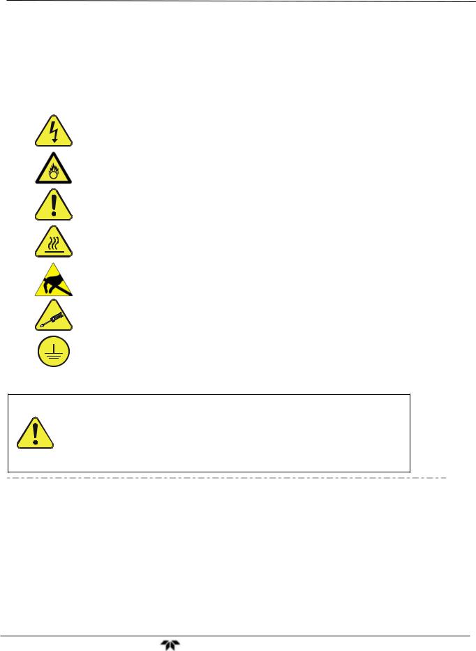
Important safety messages are provided throughout this manual for the purpose of avoiding personal injury or instrument damage. Please read these messages carefully. Each safety message is associated with a safety alert symbol, and are placed throughout this manual; the safety symbols are also located inside the instrument. It is imperative that you pay close attention to these messages, the descriptions of which are as follows:
WARNING: Electrical Shock Hazard
HAZARD: Strong oxidizer
GENERAL WARNING/CAUTION: Read the accompanying message for specific information.
CAUTION: Hot Surface Warning
Do Not Touch: Touching some parts of the instrument without protection or proper tools could result in damage to the part(s) and/or the instrument.
Technician Symbol: All operations marked with this symbol are to be performed by qualified maintenance personnel only.
Electrical Ground: This symbol inside the instrument marks the central safety grounding point for the instrument.
CAUTION
This instrument should only be used for the purpose and in the manner described in this manual. If you use this instrument in a manner other than that for which it was intended, unpredictable behavior could ensue with possible hazardous consequences.
NEVER use any gas analyzer to sample combustible gas(es)!
Note: Technical Assistance regarding the use and maintenance of the GFC7001TA or any other Teledyne product can be obtained by contacting Teledyne Customer Service Department:
Phone: 888-789-8168
Email: ask_tai@teledyne.com
or by accessing various service options on our website at http://www.teledyne-ai.com/
Teledyne Analytical Instruments |
v |
Safety Messages |
Model GFC7000TA Carbon Dioxide Analyzer |
CONSIGNES DE SÉCURITÉ
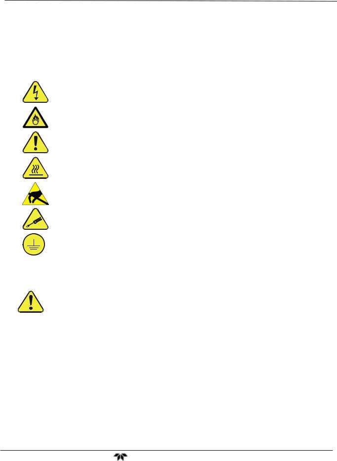
Des consignes de sécurité importantes sont fournies tout au long du présent manuel dans le but d’éviter des blessures corporelles ou d’endommager les instruments. Veuillez lire attentivement ces consignes. Chaque consigne de sécurité est représentée par un pictogramme d’alerte de sécurité; ces pictogrammes se retrouvent dans ce manuel et à l’intérieur des instruments. Les symboles correspondent aux consignes suivantes :
AVERTISSEMENT : Risque de choc électrique
DANGER : Oxydant puissant
AVERTISSEMENT GÉNÉRAL / MISE EN GARDE : Lire la consigne complémentaire pour des renseignements spécifiques
MISE EN GARDE : Surface chaude
Ne pas toucher : Toucher à certaines parties de l’instrument sans protection ou sans les outils appropriés pourrait entraîner des dommages aux pièces ou à l’instrument.
Pictogramme « technicien » : Toutes les opérations portant ce symbole doivent être effectuées uniquement par du personnel de maintenance qualifié.
Mise à la terre : Ce symbole à l’intérieur de l’instrument détermine le point central de la mise à la terre sécuritaire de l’instrument.
MISE EN GARDE
Cet instrument doit être utilisé aux fins décrites et de la manière décrite dans ce manuel. Si vous utilisez cet instrument d’une autre manière que celle pour laquelle il a été prévu, l’instrument pourrait se comporter de façon imprévisible et entraîner des conséquences dangereuses.
NE JAMAIS utiliser un analyseur de gaz pour échantillonner des gaz combustibles!
Teledyne Analytical Instruments |
vi |

Safety Messages |
Model GFC7000TA Carbon Dioxide Analyzer |
This page intentionally left blank.
Teledyne Analytical Instruments |
vii |

Manual Information |
Model GFC7000TA Carbon Dioxide Analyzer |
ABOUT THIS MANUAL
This manual, PN 07272, provides operation instructions for the GFC 7000TA Analyzer, and supports operation of the Model GFC 7000T (when used in conjunction with the GFC 7000T Addendum, PN 07273). This manual is comprised of multiple documents as listed below.
Part No. |
Rev |
Name/Description |
|
|
|
07272 |
A |
GFC 7000TA Carbon Dioxide Analyzer Operation Manual |
|
|
|
05233 |
H |
Menu trees and software documentation (inserted as Appendix A of this manual) |
|
|
|
06879 |
1/4/2011 |
Spare Parts List (located in Appendix B, this manual) |
|
|
|
04411 |
M |
Recommended Spare Parts Stocking Levels |
|
|
|
05235 |
C |
Repair Request Questionnaire (inserted as Appendix C of this manual) |
|
|
Interconnects and Schematics included in Appendix D of this manual |
|
|
|
|
|
|
0691201 |
B |
Interconnect Wire List (located in Appendix D of this manual) |
|
|
|
069121 |
B |
Interconnect Wiring Diagram (located in Appendix D of this manual) |
|
|
|
03297 |
K |
PCA, 03296, IR Photodetector Preamp and Sync Demodulator |
|
|
|
03632 |
A |
PCA, 03631, 0-20mA driver |
|
|
|
04003 |
N |
PCA, 04003, Pressure/Flow Transducer Interface |
|
|
|
04089 |
A |
PCA, 04088, Opto Pickup Interface |
|
|
|
04136 |
B |
PCA, 04135 Rev A, Relay |
|
|
|
04468 |
B |
PCA, 04467, Analog Output Series Res |
|
|
|
05803 |
B |
SCH, PCA 05802, MOTHERBOARD, GEN-5 |
|
|
|
06698 |
D |
SCH, PCA 06697, INTRFC, LCD TCH SCRN, |
|
|
|
06882 |
B |
SCH, LVDS TRANSMITTER BOARD |
|
|
|
06731 |
A |
SCH, AUXILLIARY-I/O BOARD |
|
|
|
NOTE
Please read this manual in its entirety before operating the instrument.
Teledyne Analytical Instruments |
ix |

Manual Information |
Model GFC7000TA Carbon Dioxide Analyzer |
This page intentionally left blank.
Teledyne Analytical Instruments |
x |
Table of Contents |
Model GFC7000TA Carbon Dioxide Analyzer |
TABLE OF CONTENTS |
|
SAFETY MESSAGES ............................................................................................................................................... |
v |
CONSIGNES DE SÉCURITÉ................................................................................................................................... |
vi |
ABOUT this MANUAL .............................................................................................................................................. |
ix |
TABLE OF CONTENTS ........................................................................................................................................... |
xi |
1. INTRODUCTION........................................................................................................................................................ |
1 |
1.1. Features ............................................................................................................................................................. |
1 |
1.2. Using This Manual.............................................................................................................................................. |
1 |
2. SPECIFICATIONS AND APPROVALS ..................................................................................................................... |
5 |
2.1. Specifications ..................................................................................................................................................... |
5 |
2.2. CE Mark Compliance ......................................................................................................................................... |
7 |
3. GETTING STARTED ................................................................................................................................................. |
9 |
3.1. Unpacking and Initial Set Up .............................................................................................................................. |
9 |
3.2. Front Panel....................................................................................................................................................... |
11 |
3.3. Rear Panel ....................................................................................................................................................... |
15 |
3.4. Internal Layout ................................................................................................................................................. |
17 |
3.5. Electrical Connections...................................................................................................................................... |
19 |
3.5.1. Power Connection .................................................................................................................................... |
20 |
3.5.2. Connecting Analog Inputs (Option 64)...................................................................................................... |
20 |
3.5.3. Connecting Analog Outputs...................................................................................................................... |
21 |
3.5.4. Connecting the Status Outputs ................................................................................................................. |
23 |
3.5.5. Connecting the Control Inputs .................................................................................................................. |
24 |
3.5.6. Connecting the Communications Interfaces ............................................................................................. |
25 |
3.6. Pneumatic Connections ................................................................................................................................... |
25 |
3.6.1. Basic Pneumatic Connections .................................................................................................................. |
26 |
3.6.2. Connections with Internal Valve Options Installed .................................................................................... |
30 |
3.6.3. Pneumatic Connections in Multipoint Calibration Applications.................................................................. |
32 |
3.6.4. Setting the Internal Purge Air Pressure .................................................................................................... |
32 |
3.7. Initial Operation ................................................................................................................................................ |
33 |
3.7.1. Startup ...................................................................................................................................................... |
33 |
3.7.2. Warm Up................................................................................................................................................... |
34 |
3.7.3. Warning Messages ................................................................................................................................... |
34 |
3.7.4. Functional Check ...................................................................................................................................... |
36 |
3.8. Initial Calibration Procedure ............................................................................................................................. |
37 |
3.8.1. Initial O2 Sensor Calibration Procedure .................................................................................................... |
40 |
4. FREQUENTLY ASKED QUESTIONS ..................................................................................................................... |
45 |
4.1. FAQ’s ............................................................................................................................................................... |
45 |
4.2. Glossary ........................................................................................................................................................... |
46 |
5. OPTIONAL HARDWARE AND SOFTWARE .......................................................................................................... |
51 |
5.1. Rack Mount Kits (Options 20A, 20B, 21 and 23) .............................................................................................. |
51 |
5.2. Current Loop Analog Outputs (Option 41)........................................................................................................ |
51 |
5.2.1. Converting Current Loop Analog Outputs to Standard Voltage Outputs................................................... |
52 |
5.3. Expendable Kits (Options 42C, 42D and 43).................................................................................................... |
53 |
5.4. Calibration Valves Options ............................................................................................................................... |
54 |
5.4.1. Ambient Zero/Pressurized Span Valve ..................................................................................................... |
54 |
5.4.2. Ambient Zero/Ambient Span Valve........................................................................................................... |
55 |
5.5. Communication Options ................................................................................................................................... |
57 |
5.5.1. Communications Cables........................................................................................................................... |
57 |
5.5.2. RS-232 Multidrop (Option 62) ................................................................................................................... |
57 |
5.6. Oxygen Sensor (OPT 65)................................................................................................................................. |
58 |
5.6.1. Theory of Operation.................................................................................................................................. |
58 |
5.7. Special Features .............................................................................................................................................. |
61 |
5.7.1. Dilution Ratio Option................................................................................................................................. |
61 |
5.7.2. Maintenance Mode Switch........................................................................................................................ |
61 |
5.7.3. Second Language Switch ......................................................................................................................... |
61 |
6. OPERATING INSTRUCTIONS ................................................................................................................................ |
63 |
6.1. Overview of Operating modes.......................................................................................................................... |
63 |
6.2. Sample Mode ................................................................................................................................................... |
64 |
Teledyne Analytical Instruments |
xi |

Table of Contents |
Model GFC7000TA Carbon Dioxide Analyzer |
6.2.1. Test Functions .......................................................................................................................................... |
65 |
6.2.2. Warning Messages ................................................................................................................................... |
67 |
6.3. Calibration Mode .............................................................................................................................................. |
68 |
6.4. SETUP MODE.................................................................................................................................................. |
69 |
6.5. SETUP CFG: Viewing the Analyzer’s Configuration Information ................................................................. |
70 |
6.6. SETUP ACAL: Automatic Calibration .......................................................................................................... |
70 |
6.7. SETUP DAS: Using the Data Acquisition System (DAS)............................................................................. |
71 |
6.7.1. DAS Structure........................................................................................................................................... |
72 |
6.7.2. Default DAS Channels.............................................................................................................................. |
74 |
6.7.3. Remote DAS Configuration....................................................................................................................... |
88 |
6.8. SETUP RNGE: Analog Output Reporting Range Configuration .................................................................. |
89 |
6.8.1. Physical Range versus Analog Output Reporting Ranges........................................................................ |
90 |
6.8.2. Reporting Range Modes........................................................................................................................... |
90 |
6.8.3. Single Range Mode (SNGL) ..................................................................................................................... |
92 |
6.8.4. Dual Range Mode (DUAL)........................................................................................................................ |
93 |
6.8.5. Auto Range Mode (AUTO)........................................................................................................................ |
94 |
6.8.6. Range Units .............................................................................................................................................. |
95 |
6.8.7. Dilution Ratio ............................................................................................................................................ |
96 |
6.9. SETUP PASS: Password Feature ............................................................................................................... |
97 |
6.10. SETUP CLK: Setting the Internal Time-of-Day Clock ................................................................................ |
99 |
6.11. SETUP MORE COMM: Using the Analyzer’s Communication Ports.................................................... |
101 |
6.11.1. Analyzer ID ........................................................................................................................................... |
101 |
6.11.2. COM Port Default Settings.................................................................................................................... |
102 |
6.11.3. RS-485 Configuration of COM2 ............................................................................................................ |
105 |
6.11.4. DTE and DCE Communication ............................................................................................................. |
105 |
6.11.5. COM Port Communication Modes ........................................................................................................ |
106 |
6.11.6. Remote Access via the Ethernet........................................................................................................... |
108 |
6.11.7. Multidrop RS-232 Set Up...................................................................................................................... |
114 |
6.11.8. COM Port Baud Rate............................................................................................................................ |
116 |
6.11.9. COM Port Testing ................................................................................................................................. |
117 |
6.12. SETUP MORE VARS: Internal Variables (VARS) ............................................................................... |
118 |
6.13. SETUP MORE DIAG: Using the Diagnostics Functions..................................................................... |
120 |
6.13.1. Accessing the Diagnostic Features....................................................................................................... |
121 |
6.13.2. Signal I/O.............................................................................................................................................. |
121 |
6.13.3. Analog Output Step Test ...................................................................................................................... |
122 |
6.13.4. Analog I/O Configuration ...................................................................................................................... |
123 |
6.13.5. Electric Test .......................................................................................................................................... |
136 |
6.13.6. Dark Calibration Test ............................................................................................................................ |
137 |
6.13.7. Pressure Calibration ............................................................................................................................. |
138 |
6.13.8. Flow Calibration .................................................................................................................................... |
139 |
6.13.9. Test Channel Output............................................................................................................................. |
140 |
6.14. SETUP MORE ALRM: Using the Gas Concentration Alarms............................................................... |
141 |
6.14.1. Setting the Concentration Alarm Limits................................................................................................. |
142 |
6.15. Remote Operation of the Analyzer ............................................................................................................... |
142 |
6.15.1. Remote Operation Using the External Digital I/O.................................................................................. |
142 |
6.15.2. Remote Operation Using the External Serial I/O .................................................................................. |
146 |
6.15.3. Additional Communications Documentation ......................................................................................... |
153 |
6.15.4. Using the GFC 7000TA with a Hessen Protocol Network..................................................................... |
153 |
7. CALIBRATION PROCEDURES ............................................................................................................................ |
161 |
7.1. Before Calibration........................................................................................................................................... |
161 |
7.1.1. Zero Air and Span Gas ........................................................................................................................... |
161 |
7.1.2. Calibration Gas Traceability.................................................................................................................... |
162 |
7.1.3. Data Recording Devices ......................................................................................................................... |
162 |
7.2. Manual Calibration without Zero/Span Valves................................................................................................ |
162 |
7.3. Manual Calibration Checks ............................................................................................................................ |
165 |
7.4. Manual Calibration with Zero/Span Valves..................................................................................................... |
166 |
7.5. Manual Calibration Checks with Zero/Span Valves........................................................................................ |
171 |
7.5.1. Zero/Span Calibration on Auto Range or Dual Ranges .......................................................................... |
172 |
7.5.2. Use of Zero/Span Valves with Remote Contact Closure ........................................................................ |
173 |
7.6. Automatic Zero/Span Cal/Check (AutoCal) .................................................................................................... |
173 |
7.6.1. AutoCal with Auto or Dual Reporting Ranges Modes Selected .............................................................. |
176 |
7.7. Calibration Quality .......................................................................................................................................... |
176 |
Teledyne Analytical Instruments |
xii |

Table of Contents |
Model GFC7000TA Carbon Dioxide Analyzer |
8. MAINTENANCE SCHEDULE & PROCEDURES .................................................................................................. |
179 |
8.1. Maintenance Schedule................................................................................................................................... |
179 |
8.2. Predicting Failures Using the Test Functions ................................................................................................. |
183 |
8.3. Maintenance Procedures ............................................................................................................................... |
184 |
8.3.1. Replacing the Sample Particulate Filter.................................................................................................. |
184 |
8.3.2. Rebuilding the Sample Pump ................................................................................................................. |
185 |
8.3.3. Performing Leak Checks ........................................................................................................................ |
185 |
8.3.4. Performing a Sample Flow Check .......................................................................................................... |
186 |
8.3.5. Cleaning the Optical Bench .................................................................................................................... |
186 |
8.3.6. Cleaning Exterior Surfaces of the GFC 7000TA ..................................................................................... |
186 |
9. THEORY OF OPERATION.................................................................................................................................... |
187 |
9.1. Measurement Method .................................................................................................................................... |
187 |
9.1.1. Beer’s Law.............................................................................................................................................. |
187 |
9.1.2. Measurement Fundamentals .................................................................................................................. |
187 |
9.1.3. Gas Filter Correlation.............................................................................................................................. |
188 |
9.1.4. Interference and Signal to Noise Rejection............................................................................................. |
190 |
9.2. Pneumatic Operation...................................................................................................................................... |
193 |
9.2.1. Sample Gas Flow ................................................................................................................................... |
194 |
9.2.2. Flow Rate Control ................................................................................................................................... |
194 |
9.2.3. Purge Gas Pressure Control................................................................................................................... |
196 |
9.2.4. Particulate Filter...................................................................................................................................... |
196 |
9.2.5. Pneumatic Sensors................................................................................................................................. |
196 |
9.3. Electronic Operation....................................................................................................................................... |
197 |
9.3.1. Overview................................................................................................................................................. |
197 |
9.3.2. CPU ........................................................................................................................................................ |
199 |
9.3.3. Optical Bench & GFC Wheel .................................................................................................................. |
200 |
9.3.4. Synchronous Demodulator (Sync/Demod) Assembly ............................................................................. |
202 |
9.3.5. Relay Board ............................................................................................................................................ |
205 |
9.3.6. Mother Board .......................................................................................................................................... |
207 |
9.3.7. I2C Data Bus ........................................................................................................................................... |
210 |
9.3.8. Power Supply/ Circuit Breaker ................................................................................................................ |
211 |
9.4. Front Panel Touchscreen/Display Interface ................................................................................................... |
212 |
9.4.1. LVDS Transmitter Board......................................................................................................................... |
212 |
9.4.2. Front Panel Touchscreen/Display Interface PCA.................................................................................... |
212 |
9.5. Software Operation ........................................................................................................................................ |
213 |
9.5.1. Adaptive Filter......................................................................................................................................... |
213 |
9.5.2. Calibration - Slope and Offset................................................................................................................. |
214 |
9.5.3. Measurement Algorithm.......................................................................................................................... |
214 |
9.5.4. Temperature and Pressure Compensation............................................................................................. |
215 |
9.5.5. Internal Data Acquisition System (DAS) ................................................................................................. |
215 |
10. TROUBLESHOOTING & REPAIR PROCEDURES ............................................................................................ |
217 |
10.1. General Troubleshooting Hints..................................................................................................................... |
217 |
10.1.1. Interpreting WARNING Messages ........................................................................................................ |
218 |
10.1.2. Fault Diagnosis with TEST Functions ................................................................................................... |
221 |
10.1.3. Using the Diagnostic Signal I/O Function ............................................................................................. |
223 |
10.1.4. Internal Electronic Status LEDs ............................................................................................................ |
224 |
10.2. Gas Flow Problems ...................................................................................................................................... |
228 |
10.2.1. GFC 7000TA Internal Gas Flow Diagrams ........................................................................................... |
229 |
10.2.2. Typical Sample Gas Flow Problems ..................................................................................................... |
232 |
10.2.3. Poor or Stopped Flow of Purge Gas ..................................................................................................... |
234 |
10.3. Calibration Problems .................................................................................................................................... |
235 |
10.3.1. Miscalibrated......................................................................................................................................... |
235 |
10.3.2. Non-Repeatable Zero and Span ........................................................................................................... |
236 |
10.3.3. Inability to Span – Touchscreen SPAN Button Not Visible ................................................................... |
236 |
10.3.4. Inability to Zero – Touchscreen ZERO Button Not Visible .................................................................... |
237 |
10.4. Other Performance Problems....................................................................................................................... |
238 |
10.4.1. Temperature Problems ......................................................................................................................... |
238 |
10.4.2. Excessive Noise ................................................................................................................................... |
240 |
10.5. Subsystem Checkout ................................................................................................................................... |
241 |
10.5.1. AC Mains Configuration........................................................................................................................ |
241 |
10.5.2. DC Power Supply ................................................................................................................................. |
241 |
10.5.3. I2C Bus.................................................................................................................................................. |
242 |
Teledyne Analytical Instruments |
xiii |

Table of Contents |
Model GFC7000TA Carbon Dioxide Analyzer |
10.5.4. Touchscreen Interface .......................................................................................................................... |
242 |
10.5.5. LCD Display Module ............................................................................................................................. |
242 |
10.5.6. Relay Board .......................................................................................................................................... |
243 |
10.5.7. Sensor Assembly.................................................................................................................................. |
243 |
10.5.8. Motherboard ......................................................................................................................................... |
245 |
10.5.9. CPU ...................................................................................................................................................... |
249 |
10.5.10. RS-232 Communications.................................................................................................................... |
249 |
10.6. Repair Procedures ....................................................................................................................................... |
251 |
10.6.1. Repairing Sample Flow Control Assembly............................................................................................ |
251 |
10.6.2. Removing/Replacing the GFC Wheel ................................................................................................... |
252 |
10.6.3. Disk-On-Module Replacement Procedure ............................................................................................ |
253 |
11. A PRIMER ON ELECTRO-STATIC DISCHARGE............................................................................................... |
255 |
11.1. How Static Charges are Created.................................................................................................................. |
255 |
11.2. How Electro-Static Charges Cause Damage ............................................................................................... |
256 |
11.3. Common Myths About ESD Damage ........................................................................................................... |
257 |
11.4. Basic Principles of Static Control.................................................................................................................. |
257 |
LIST OF APPENDICES
APPENDIX A - VERSION SPECIFIC SOFTWARE DOCUMENTATION, L.8
APPENDIX A-1: Models GFC 7000TA and GFC 7000E Software Menu Trees APPENDIX A-2: GFC 7000 Series Setup Variables
APPENDIX A-3: GFC 7000 Series Warnings and Test Measurements APPENDIX A-4: GFC 7000 Series Signal I/O Definitions
APPENDIX A-5: GFC 7000 Series DAS Triggering Events APPENDIX A-6: GFC 7000 Series DAS Parameters APPENDIX A-7: Terminal Command Designators APPENDIX A-8: Terminal Key Assignments
APPENDIX A-9: GFC 7000 Series MODBUS Register
APPENDIX B - SPARE PARTS LIST and RECOMMENDED SPARES STOCKING LEVELS APPENDIX C - REPAIR QUESTIONNAIRE
APPENDIX D - ELECTRONIC SCHEMATICS
Teledyne Analytical Instruments |
xiv |

Table of Contents |
Model GFC7000TA Carbon Dioxide Analyzer |
|
|
LIST OF FIGURES |
|
|
|
Figure 3-1: |
Front Panel Layout ...................................................................................................................... |
|
11 |
Figure 3-2: |
Display Screen and Touch Control ............................................................................................. |
12 |
|
Figure 3-3: |
Display/Touch Control Screen Mapped to Menu Charts............................................................. |
14 |
|
Figure 3-4: |
Rear Panel Layout....................................................................................................................... |
|
15 |
Figure 3-5: |
Internal Chassis Layout............................................................................................................... |
|
17 |
Figure 3-6: |
Optical Bench Layout .................................................................................................................. |
|
18 |
Figure 3-7: |
GFC 7000TA Internal Gas Flow.................................................................................................. |
19 |
|
Figure 3-8: |
Analog In Connector.................................................................................................................... |
|
20 |
Figure 3-9: |
Pneumatic Connections–Basic Configuration–Using Bottled Span Gas .................................... |
27 |
|
Figure 3-10: |
Pneumatic Connections–Basic Configuration–Using Gas Dilution Calibrator ............................ |
27 |
|
Figure 3-11: |
Pneumatic Connections with Ambient Zero/Ambient Span Valves (OPT 50A) .......................... |
30 |
|
Figure 3-12: |
Pneumatic Connections with Ambient Zero/Ambient Span Valves (Opt 50A) and |
|
|
|
External Zero Air Scrubber.......................................................................................................... |
|
30 |
Figure 3-13: |
Pneumatic Connections with Ambient Zero/Pressurized Span Valves (OPT 50B) .................... |
31 |
|
Figure 3-14: |
Pneumatic Connections with Ambient Zero/Pressurized Span Valves (Opt 50B) and |
|
|
|
External Zero Air Scrubber.......................................................................................................... |
|
31 |
Figure 3-15: |
Example of Pneumatic Set up for Multipoint Calibration............................................................. |
32 |
|
Figure 3-16: |
O2 Sensor Calibration Set Up ..................................................................................................... |
|
40 |
Figure 5-1: |
Current Loop Option Installed on the Motherboard..................................................................... |
52 |
|
Figure 5-2: |
Internal Pneumatic Flow – Ambient Zero/Pressurized Span Valves........................................... |
55 |
|
Figure 5-3: |
Internal Pneumatic Flow – Ambient Zero/Ambient Span ............................................................ |
56 |
|
Figure 5-4: |
Multi-drop/LVDS PCA Seated on CPU ....................................................................................... |
58 |
|
Figure 5-5: |
Oxygen Sensor - Principle of Operation...................................................................................... |
59 |
|
Figure 5-6: |
GFC 7000TA – Internal Pneumatics with O2 Sensor Option 65................................................. |
60 |
|
Figure 6-1: |
Front Panel Display ..................................................................................................................... |
|
63 |
Figure 6-2: |
Viewing TEST Functions ............................................................................................................. |
|
66 |
Figure 6-3: |
Viewing and Clearing GFC 7000TA WARNING Messages ........................................................ |
68 |
|
Figure 6-4: |
Default DAS Channels Setup ...................................................................................................... |
|
75 |
Figure 6-5: |
APICOM User Interface for DAS Configuration .......................................................................... |
88 |
|
Figure 6-6: |
Analog Output Connector Pin Out............................................................................................... |
89 |
|
Figure 6-7: |
Rear Panel Connector Pin-Outs for COM1 & COM2 in RS-232 Mode ..................................... |
103 |
|
Figure 6-8: |
CPU Connector Pin-Outs for COM1 & COM2 in RS-232 Mode ............................................... |
104 |
|
Figure 6-9: |
Multidrop/LVDS PCA Seated on CPU....................................................................................... |
114 |
|
Figure 6-10: |
RS232-Multidrop PCA Host/Analyzer Interconnect Diagram.................................................... |
115 |
|
Figure 6-11: |
Setup for Calibrating Analog Voltage Outputs .......................................................................... |
130 |
|
Figure 6-12: |
Setup for Calibrating Current Outputs....................................................................................... |
132 |
|
Figure 6-13: |
Status Output Connector........................................................................................................... |
|
143 |
Figure 6-14: |
Control Inputs ............................................................................................................................ |
|
145 |
Figure 6-15: |
APICOM Remote Control Program Interface ............................................................................ |
152 |
|
Figure 7-1: |
Pneumatic Connections–Basic Configuration–Using Bottled Span Gas .................................. |
162 |
|
Figure 7-2: |
Pneumatic Connections–Basic Configuration–Using Gas Dilution Calibrator .......................... |
163 |
|
Figure 7-3: |
Pneumatic Connections – Ambient Zero/Pressurized Span Valves ........................................ |
166 |
|
Figure 7-4: |
Pneumatic Connections – Ambient Zero/Pressurized Span Valves and External Zero Air |
|
|
|
Scrubber .................................................................................................................................... |
|
167 |
Figure 7-5: |
Pneumatic Connections – Ambient Zero/Ambient Span Valves ............................................... |
167 |
|
Figure 7-6: |
Pneumatic Connections – Ambient Zero/Ambient Span Valves with External Zero Air |
|
|
|
Scrubber .................................................................................................................................... |
|
168 |
Figure 8-1: |
Sample Particulate Filter Assembly .......................................................................................... |
184 |
|
Figure 9-1: |
Measurement Fundamentals..................................................................................................... |
|
188 |
Figure 9-2: |
GFC Wheel................................................................................................................................ |
|
188 |
Figure 9-3: |
Measurement Fundamentals with GFC Wheel ......................................................................... |
189 |
|
Figure 9-4: |
Affect of CO2 in the Sample on CO2 MEAS & CO2 REF......................................................... |
190 |
|
Figure 9-5: |
Effects of Interfering Gas on CO2 MEAS & CO2 REF.............................................................. |
191 |
|
Teledyne Analytical Instruments |
xv |

Table of Contents |
Model GFC7000TA Carbon Dioxide Analyzer |
|
||
Figure 9-6: |
|
Chopped IR Signal .................................................................................................................... |
|
191 |
Figure 9-7: |
|
Internal Pneumatic Flow – Basic Configuration ........................................................................ |
194 |
|
Figure 9-8: |
|
Flow Control Assembly & Critical Flow Orifice .......................................................................... |
195 |
|
Figure 9-9: |
|
GFC 7000TA Electronic Block Diagram.................................................................................... |
198 |
|
Figure 9-10: |
CPU Board ................................................................................................................................ |
|
199 |
|
Figure 9-11: |
GFC Light Mask ........................................................................................................................ |
|
201 |
|
Figure 9-12: |
Segment Sensor and M/R Sensor Output................................................................................. |
202 |
||
Figure 9-13: |
GFC 7000TA Sync / Demod Block Diagram ............................................................................. |
203 |
||
Figure 9-14: |
Sample & Hold Timing............................................................................................................... |
|
204 |
|
Figure 9-15: |
Location of relay board Status LED’s........................................................................................ |
207 |
||
Figure 9-16: |
Power Distribution Block Diagram............................................................................................. |
211 |
||
Figure 9-17: |
Front Panel and Display Interface Block Diagram .................................................................... |
212 |
||
Figure 9-18: |
Basic Software Operation.......................................................................................................... |
|
213 |
|
Figure 10-1: |
Viewing and Clearing Warning Messages ................................................................................ |
219 |
||
Figure 10-2: |
Example of Signal I/O Function................................................................................................. |
224 |
||
Figure 10-3: |
CPU Status Indicator................................................................................................................. |
|
225 |
|
Figure 10-4: |
Sync/Demod Board Status LED Locations ............................................................................... |
226 |
||
Figure 10-5: |
Relay Board Status LEDs.......................................................................................................... |
|
226 |
|
Figure 10-6: |
GFC 7000TA – Basic Internal Gas Flow ................................................................................... |
229 |
||
Figure 10-7: |
Internal Pneumatic Flow – Ambient Zero/Pressurized Span Valves......................................... |
230 |
||
Figure 10-8: |
Internal Pneumatic Flow – Ambient Zero/Ambient Span .......................................................... |
231 |
||
Figure 10-9: |
GFC 7000TA – Internal Pneumatics with O2 Sensor Option 65A ............................................. |
232 |
||
Figure 10-10: |
Critical Flow Restrictor Assembly Disassembly ........................................................................ |
251 |
||
Figure 10-11: |
Opening the GFC Wheel Housing............................................................................................. |
252 |
||
Figure 10-12: |
Removing the GFC Wheel ........................................................................................................ |
|
253 |
|
Figure 11-1: |
Triboelectric Charging ............................................................................................................... |
|
255 |
|
Figure 11-2: |
Basic anti-ESD Work Station..................................................................................................... |
|
258 |
|
LIST OF TABLES |
|
|
||
Table 2-1: |
Model GFC 7000TA Basic Unit Specifications ..................................................................................... |
5 |
||
Table 3-1: |
Display and Touchscreen Control Description ................................................................................... |
13 |
||
Table 3-2: |
Rear Panel Description....................................................................................................................... |
|
16 |
|
Table 3-3: |
Analog Input Pin Assignments............................................................................................................ |
|
21 |
|
Table 3-4: |
GFC 7000TA Analog Output Pin Outs................................................................................................ |
22 |
||
Table 3-5: |
Status Output Pin-outs........................................................................................................................ |
|
23 |
|
Table 3-6: |
Control Input Pin-outs ......................................................................................................................... |
|
24 |
|
Table 3-7: |
Rear Panel Pneumatic Connections................................................................................................... |
26 |
||
Table 3-8: |
Front Panel Display During System Warm-Up ................................................................................... |
34 |
||
Table 3-9: |
Possible Warning Messages at Start-Up............................................................................................ |
35 |
||
Table 5-1: |
Ambient Zero/Pressurized Span Valve Operating States .................................................................. |
54 |
||
Table 5-2: |
Ambient Zero/Ambient Span Valve Operating States ........................................................................ |
55 |
||
Table 6-1: |
Analyzer Operating modes ................................................................................................................. |
|
64 |
|
Table 6-2: |
Test Functions Defined....................................................................................................................... |
|
65 |
|
Table 6-3: |
List of Warning Messages .................................................................................................................. |
|
67 |
|
Table 6-4: |
Primary Setup Mode Features and Functions .................................................................................... |
69 |
||
Table 6-5: |
Secondary Setup Mode Features and Functions ............................................................................... |
69 |
||
Table 6-6: |
Front Panel Sample LED Status Indicators for DAS .......................................................................... |
71 |
||
Table 6-7: |
DAS Data Channel Properties ............................................................................................................ |
|
72 |
|
Table 6-8: |
DAS Data Parameter Functions ......................................................................................................... |
|
73 |
|
Table 6-9: |
Password Levels................................................................................................................................. |
|
97 |
|
Table 6-10: |
Com Port Communication Modes..................................................................................................... |
|
106 |
|
Table 6-11: |
Ethernet Status Indicators ................................................................................................................ |
|
108 |
|
Table 6-12: |
LAN/Internet Configuration Properties.............................................................................................. |
109 |
||
Table 6-13: |
Internet Configuration Touchscreen Functions................................................................................. |
113 |
||
Teledyne Analytical Instruments |
xvi |

Table of Contents |
Model GFC7000TA Carbon Dioxide Analyzer |
|
|
Table 6-14: |
Variable Names (VARS) Revision B.3.............................................................................................. |
118 |
|
Table 6-15: |
GFC 7000TA Diagnostic (DIAG) Functions...................................................................................... |
120 |
|
Table 6-16: |
DIAG - Analog I/O Functions ............................................................................................................ |
|
123 |
Table 6-17: Analog Output Voltage Ranges ....................................................................................................... |
|
124 |
|
Table 6-18: |
Analog Output Current Loop Range |
................................................................................................. |
125 |
Table 6-19: |
Analog Output Pin Assignments....................................................................................................... |
|
125 |
Table 6-20: |
Voltage Tolerances for Analog Output Calibration ........................................................................... |
129 |
|
Table 6-21: |
Current Loop Output Calibration with Resistor ................................................................................. |
133 |
|
Table 6-22: |
Test Parameters Available for Analog Output A4............................................................................. |
140 |
|
Table 6-23: |
CO2 Concentration Alarm Default Settings....................................................................................... |
141 |
|
Table 6-24: |
Status Output Pin Assignments........................................................................................................ |
|
144 |
Table 6-25: |
Control Input Pin Assignments ......................................................................................................... |
|
145 |
Table 6-26: |
Terminal Mode Software Commands ............................................................................................... |
146 |
|
Table 6-27: |
Command Types .............................................................................................................................. |
|
147 |
Table 6-28: |
Serial Interface Documents .............................................................................................................. |
|
153 |
Table 6-29: |
RS-232 Communication Parameters for Hessen Protocol ............................................................... |
154 |
|
Table 6-30: |
Teledyne Instruments Hessen Protocol Response Modes .............................................................. |
156 |
|
Table 6-31: |
Default Hessen Status Bit Assignments ........................................................................................... |
158 |
|
Table 7-1: |
AUTOCAL Modes ............................................................................................................................. |
|
173 |
Table 7-2: |
AutoCal ATTRIBUTE Setup Parameters.......................................................................................... |
173 |
|
Table 7-3: |
Calibration Data Quality Evaluation.................................................................................................. |
|
176 |
Table 8-1: |
GFC 7000TA Maintenance Schedule............................................................................................... |
181 |
|
Table 8-2: |
GFC 7000TA Test Function Record |
................................................................................................. |
182 |
Table 8-3: |
Predictive uses for Test Functions.................................................................................................... |
|
183 |
Table 9-1: |
Sync/Demod Status LED Activity...................................................................................................... |
|
204 |
Table 9-2: |
Relay Board Status LED’s ................................................................................................................ |
|
206 |
Table 10-1: |
Warning Messages - Indicated Failures ........................................................................................... |
220 |
|
Table 10-2: |
Test Functions - Indicated Failures .................................................................................................. |
|
222 |
Table 10-3: |
Sync/Demod Board Status Failure Indications ................................................................................. |
225 |
|
Table 10-4: |
I2C Status LED Failure Indications................................................................................................... |
|
226 |
Table 10-5: |
Relay Board Status LED Failure Indications .................................................................................... |
227 |
|
Table 10-6: |
DC Power Test Point and Wiring Color Codes................................................................................. |
241 |
|
Table 10-7: |
DC Power Supply Acceptable Levels ............................................................................................... |
242 |
|
Table 10-8: |
Relay Board Control Devices............................................................................................................ |
|
243 |
Table 10-9: |
Opto Pickup Board Nominal Output Frequencies............................................................................. |
244 |
|
Table 10-10: |
Analog Output Test Function - Nominal Values Voltage Outputs .................................................... |
247 |
|
Table 10-11: |
Analog Output Test Function - Nominal Values Current Outputs..................................................... |
247 |
|
Table 10-12: |
Status Outputs Check....................................................................................................................... |
|
248 |
Table 11-1: |
Static Generation Voltages for Typical Activities .............................................................................. |
255 |
|
Table 11-2: |
Sensitivity of Electronic Devices to Damage by ESD....................................................................... |
256 |
|
Teledyne Analytical Instruments |
xvii |

Table of Contents |
Model GFC7000TA Carbon Dioxide Analyzer |
This page intentionally left blank.
Teledyne Analytical Instruments |
xviii |

Introduction |
Model GFC7000TA Carbon Dioxide Analyzer |
1. INTRODUCTION
The Models GFC 7000TA and GFC 7000TM differ only in specifications; unless clearly differentiated, both models in this manual are referred to as the GFC 7000TA for simplification. The GFC 7000TA measures carbon dioxide CO2 by comparing infrared energy absorbed by a sample to that absorbed by a reference according to the Beer-Lambert law. This is accomplished by using a Gas Filter Wheel which alternately allows a high energy infrared light source to pass through a CO2 filled chamber and a chamber with no CO2 present.
The light then travels through the sample cell, which has a folded path. The energy loss through the sample cell is compared with the zero reference signal provided by the gas filter to produce an output proportional to concentration, with little effect from interfering gases within the sample. A nitrogen purge system is provided for the GFC wheel assembly to eliminate the effects of ambient CO2, if necessary.
This design produces superior zero and span stability and a high signal-to-noise ratio, allowing excellent sensitivity. Multi-tasking software gives real time indication of numerous operating parameters and provides automatic alarms if diagnostic limits are exceeded
1.1. Features
Ranges, GFC 7000TA: 0-2 ppm to 0-2000 ppm, GFC 7000TM: 0-4 ppm to 0-4000 ppm, user selectable
Gas Filter Wheel for CO2 specific measurement
LCD Graphical User Interface with capacitive touch screen
Multi-tasking software allows viewing of test variables during operation
Continuous self checking with alarms
Bi-directional RS-232 and 10/100Base-T Ethernet (optional USB and RS-485) ports for remote operation
Front panel USB ports for peripheral devices
Digital status outputs to indicate instrument operating condition
Adaptive signal filtering to optimize response time
Temperature & Pressure compensation
Internal data logging with 1 min to 24 hour averages
1.2. Using This Manual
This manual has the following data structures:
1 TABLE OF CONTENTS:
Outlines the contents of the manual in the order the information is presented. This is a good overview of the topics covered in the manual. There is also a list of tables, a list of figures and a list of appendices.
2 SPECIFICATIONS
This section contains a list of the analyzer’s performance specifications.
Teledyne Analytical Instruments |
1 |

Introduction |
Model GFC7000TA Carbon Dioxide Analyzer |
3 GETTING STARTED:
Instructions for setting up, installing, and performing a functional check and initial calibration.
4 FAQ
Answers to the most frequently asked questions about operating the analyzer.
5 OPTIONAL HARDWARE & SOFTWARE
A description of optional equipment to add functionality to your analyzer.
6 OPERATION INSTRUCTIONS
This section includes step-by-step instructions for operating the analyzer and using its various features and functions.
7 CALIBRATION PROCEDURES
General information and step by step instructions for calibrating your analyzer.
8 EPA PROTOCOL CALIBRATION
Because CO2 is not declared a criteria air pollutant by the US EPA, EPA equivalency is not required for this type of analyzer. Therefore no special calibration methods are needed to satisfy EPA requirements.
9 INSTRUMENT MAINTENANCE
Description of certain preventative maintenance procedures that should be regularly performed on you instrument to keep it in good operating condition. This section also includes information on using the DAS to record diagnostic functions useful in predicting possible component failures before they happen.
10 THEORY OF OPERATION
An in-depth look at the various principals by which your analyzer operates as well as a description of how the various electronic, mechanical and pneumatic components of the instrument work and interact with each other. A close reading of this section is invaluable for understanding the instrument’s operation.
11 TROUBLESHOOTING
This section includes pointers and instructions for diagnosing problems with the instrument, such as excessive noise or drift, as well as instructions on performing repairs of the instrument’s major subsystems.
12. A PRIMER ON ELECTRO-STATIC DISCHARGE
Very important information on how static electricity occurs, why it is so dangerous to electronic components and assemblies as well as how to prevent that damage from occurring.
APPENDICES:
These include: software menu trees, warning messages, definitions of DAS & serial I/O variables, spare parts list, repair questionnaire, interconnect listing and drawings, and electronic schematics.
NOTE
Throughout this manual, words printed in capital, bold letters, such as SETUP or ENTR represent messages as they appear on the analyzer’s front panel display. Also, flowcharts in this manual contain typical representations of the analyzer’s display during the various operations being described. These representations are not intended to be exact and may differ slightly from the actual display of your instrument.
Teledyne Analytical Instruments |
2 |
Introduction |
Model GFC7000TA Carbon Dioxide Analyzer |
Teledyne Analytical Instruments |
3 |

Specifications |
Model GFC7000TA Carbon Dioxide Analyzer |
|
2. SPECIFICATIONS AND APPROVALS |
||
2.1. Specifications |
|
|
Table 2-1: |
Model GFC 7000TA Basic Unit Specifications |
|
|
|
|
GFC 7000TA Parameter |
|
GFC 7000TA Specification |
Ranges |
|
Min: 0-2 ppm Full scale |
(Physical Analog Output) |
|
Max: 0-2,000 ppm Full scale |
|
|
Selectable, dual ranges and auto ranging supported |
|
|
|
Measurement Units |
|
ppb, ppm, µg/m3, mg/m3, % (user selectable) |
Zero Noise |
|
< 0.1 ppm (RMS) |
Span Noise |
|
< 1% of reading (RMS) |
Lower Detectable Limit |
|
< 0.2 ppm1 |
Zero Drift (24 hours) |
|
<0.25 ppm1 |
Span Drift (24 hours) |
|
<0.5% of reading 1 |
Lag Time |
|
10 seconds |
Rise/Fall Time |
|
<60 seconds to 95% |
Linearity |
|
1% of full scale |
Precision |
|
0.5% of reading |
|
|
|
Sample Flow Rate |
|
800cm3/min. ±10% |
|
|
O2 Sensor option adds 110 cm³/min, ±20%, to total flow through when installed. |
|
|
|
Temperature Coefficient |
|
< 0.1% of Full Scale per oC |
Voltage Coefficient |
|
< 0.05% of Full Scale per V |
AC Power Rating |
|
100V-120V, 220V – 240 V, 50/60 Hz |
Analog Output Ranges |
|
10V, 5V, 1V, 0.1V (selectable) |
Analog Output Resolution |
|
1 part in 4096 of selected full-scale voltage |
|
|
|
Recorder Offset |
|
±10% |
|
|
|
Standard I/O |
|
1 Ethernet: 10/100Base-T |
|
|
2 RS-232 (300 – 115,200 baud) |
|
|
2 USB device ports |
|
|
8 opto-isolated digital status outputs |
|
|
6 opto-isolated digital control inputs (3 defined, 3 spare) |
|
|
4 analog outputs |
|
|
|
Optional I/O |
|
1 USB com port |
|
|
1 RS485 |
|
|
8 analog inputs (0-10V, 12-bit) |
|
|
4 digital alarm outputs |
|
|
Multidrop RS232 |
|
|
3 4-20mA current outputs |
|
|
|
Environmental |
|
Installation category (over-voltage category) II; Pollution degree 2 |
|
|
|
Temperature Range |
|
5-40oC |
Humidity Range |
|
0 - 95% RH, non-condensing |
Dimensions H x W x D |
|
7" x 17" x 23.5" (178 mm x 432 mm x 597 mm) |
Teledyne Analytical Instruments |
5 |

Specifications |
|
|
Model GFC7000TA Carbon Dioxide Analyzer |
|
|
|
|
|
|
GFC 7000TA Parameter |
GFC 7000TA Specification |
|||
Weight |
40 lbs. (18.1 kg) |
|||
Certifications |
CE: EN61010-1:90 + A1:92 + A2:95, EN61326 - Class A |
|||
|
|
|
|
|
1 At constant temperature and voltage. |
|
|
||
Table 2-2: Model GFC 7000TM Basic Unit Specifications |
||||
|
|
|
|
|
GFC 7000TM Parameter |
|
GFC 7000TM Specification |
|
|
Ranges |
|
Min: 0-4 ppm Full scale |
|
|
(Physical Analog Output) |
|
Max: 0-4000 ppm Full scale |
|
|
|
|
|
||
|
|
Selectable, dual ranges and auto ranging supported |
|
|
Measurement Units |
|
ppb, ppm, µg/m3, mg/m3, (selectable) |
|
|
Zero Noise |
|
< 0.2 ppm (RMS) |
|
|
Span Noise |
|
< 1% of reading (RMS) |
|
|
|
|
|
|
|
Lower Detectable Limit |
|
< 0.4 ppm1 |
|
|
Zero Drift (24 hours) |
|
<0.5 ppm1 |
|
|
Span Drift (24 hours) |
|
<0.5% of reading1 |
|
|
Lag Time |
|
10 seconds |
|
|
Rise/Fall Time |
|
<60 seconds to 95% |
|
|
|
|
|
|
|
Linearity |
|
1% of full scale |
|
|
|
|
|
|
|
Precision |
|
0.5% of reading |
|
|
Sample Flow Rate |
|
800cm3/min. ±10% |
|
|
|
|
O2 Sensor option adds 110 cm³/min, ±20%, to total flow though when installed |
|
|
Temperature Coefficient |
|
< 0.1% of Full Scale per oC or 0.1 ppm per oC, whichever is greater |
|
|
Voltage Coefficient |
|
< 0.05% of Full Scale per V |
|
|
|
|
|
|
|
AC Power Requirements |
|
100V – 120V, 220V – 240V, 50/60 Hz |
|
|
Analog Output Ranges |
|
10V, 5V, 1V, 0.1V |
|
|
Recorder Offset |
|
±10% |
|
|
|
|
|
|
|
Analog Output Resolution |
|
1 part in 4096 of selected full-scale voltage |
|
|
|
|
|
|
|
Standard I/O |
|
1 |
Ethernet: 10/100Base-T |
|
|
|
2 |
RS232 (300-115,200 baud) |
|
|
|
2 |
USB device ports |
|
|
|
8 |
Status opto-isolated digital status outputs |
|
|
|
6 |
Opto-isolated digital control inputs (3 defined, 3 spare) |
|
|
|
4 |
Analog outputs |
|
Optional I/O |
|
1 |
USB com port |
|
|
|
1 RS485 |
|
|
|
|
8 |
Analog inputs (0-10V, 12-bit) |
|
|
|
4 |
Digital alarm outputs |
|
|
|
Multidrop RS232 |
|
|
|
|
3 |
4-20mA current outputs |
|
Operating Temperature Range |
|
5-40oC |
|
|
Humidity Range |
|
0 |
- 95% RH, non-condensing |
|
Dimensions H x W x D |
|
7" x 17" x 23.5" (178 mm x 432 mm x 597 mm) |
|
|
|
|
|
|
|
Weight |
|
40 lbs. (18.1 kg) |
|
|
|
|
|
|
|
Environmental |
|
Installation category (over-voltage category) II; Pollution degree 2 |
|
|
Teledyne Analytical Instruments |
6 |

Specifications |
Model GFC7000TA Carbon Dioxide Analyzer |
|
|
|
|
GFC 7000TM Parameter |
|
GFC 7000TM Specification |
Certifications |
|
CE: EN61010-1:90 + A1:92 + A2:95, EN61326 - Class A |
1 At constant temperature and voltage. |
|
|
2.2. CE Mark Compliance
Emissions Compliance
The Teledyne Instruments Model GFC 7000TA Gas Filter Correlation CO2 Analyzer was tested and found to be fully compliant with:
EN61326 (1997 w/A1: 98) Class A, FCC Part 15 Subpart B section 15.107 Class A, ICES-003 Class A (ANSI C63.4 1992) & AS/NZS 3548 (w/A1 & A2; 97) Class A.
Safety Compliance
The Teledyne Instruments Model GFC 7000TA Gas Filter Correlation CO2 Analyzer was tested and found to be fully compliant with:
IEC 61010-1:90 + A1:92 + A2:95
Teledyne Analytical Instruments |
7 |
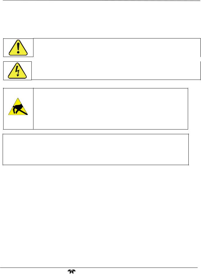
Getting Started |
Model GFC7000TA Carbon Dioxide Analyzer |
3. GETTING STARTED
3.1. Unpacking and Initial Set Up
CAUTION
To avoid personal injury, always use two persons to lift and carry the Model GFC 7000TA.
WARNING
Never disconnect PCAs, wiring harnesses or electronic subassemblies while the instrument is under power.
CAUTION – Avoid Warranty Invalidation
Printed circuit assemblies (PCAs) are sensitive to electro-static discharges too small to be felt by the human nervous system. Damage resulting from failure to use ESD protection when working with electronic assemblies will void the instrument warranty.
See A Primer on Electro-Static Discharge in this manual for more information on preventing ESD damage.
NOTE
It is recommended that you store shipping containers/materials for future use if/when the instrument should be returned to the factory for repair and/or calibration service. See Warranty section in this manual and shipping procedures on our Website at:
http://www.teledyne-api.com under Customer Support > Return Authorization.
1.Verify that there is no apparent external shipping damage. If damage has occurred, please advise the shipper first, then Teledyne Instruments.
2.Included with your analyzer is a printed record of the final performance characterization performed on your instrument at the factory. This record, titled Final Test and Validation Data Sheet (P/N 04596) is an important quality assurance and calibration record for this instrument. It should be placed in the quality records file for this instrument.
3.Carefully remove the top cover of the analyzer and check for internal shipping damage.
Remove the set-screw located in the top, center of the Front panel.
Remove the 2 screws fastening the top cover to the unit (one per side towards the rear).
Slide the cover backwards until it clears the analyzer’s front bezel.
Lift the cover straight up.
Teledyne Analytical Instruments |
9 |

Getting Started |
Model GFC7000TA Carbon Dioxide Analyzer |
4.Inspect the interior of the instrument to make sure all circuit boards and other components are in good shape and properly seated.
5.Check the connectors of the various internal wiring harnesses and pneumatic hoses to make sure they are firmly and properly seated.
6.Verify that all of the optional hardware ordered with the unit has been installed. These are listed on the paperwork accompanying the analyzer.
VENTILATION CLEARANCE: Whether the analyzer is set up on a bench or installed into an instrument rack, be sure to leave sufficient ventilation clearance.
AREA |
MINIMUM REQUIRED CLEARANCE |
Back of the instrument |
4 in. |
|
|
Sides of the instrument |
1 in. |
|
|
Above and below the instrument |
1 in. |
|
|
Various rack mount kits are available for this analyzer. See Section 5.1 of this manual for more information.
Teledyne Analytical Instruments |
10 |
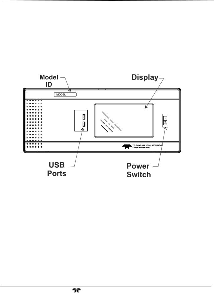
Getting Started |
Model GFC7000TA Carbon Dioxide Analyzer |
3.2. Front Panel
Figure 3-1 shows the analyzer’s front panel layout, followed by a close-up of the display screen in Figure 3-2, which is described in Table 3-1. The two USB ports on the front panel are provided for the connection of peripheral devices:
plug-in mouse (not included) to be used as an alternative to the touchscreen interface
thumb drive (not included) to download updates to instruction software (contact TAI Customer Service for information).
Figure 3-1: Front Panel Layout
Teledyne Analytical Instruments |
11 |

Getting Started |
Model GFC7000TA Carbon Dioxide Analyzer |
Figure 3-2: Display Screen and Touch Control
CAUTION – Avoid Damaging Touchscreen
Do not use hard-surfaced instruments such as pens to operate the touchscreen.
The front panel liquid crystal display includes touch control. Upon analyzer start-up, the display shows a splash screen and other initialization indicators before the main display appears, similar to Figure 3-2 above (may or may not display a Fault alarm). The LEDs on the display screen indicate the Sample, Calibration and Fault states; also on the screen is the gas concentration field (Conc), which displays realtime readouts for the primary gas and for the secondary gas if installed. The display screen also shows which mode the analyzer is currently in (Mode field), as well as messages and data (Param field). Along the bottom of the screen is a row of touch control buttons; only those that are currently applicable will have a label. Table 3-1 provides detailed information for each component of the screen.
Teledyne Analytical Instruments |
12 |
 Loading...