


OPERATING INSTRUCTIONS FOR
Model 7600
NDIR Infrared Gas Analyzer
P/N M7600
ECO:
DANGER
Toxic gases and or flammable liquids may be present in this monitoring system. Personal protective equipment may be required when servicing this instrument.
Hazardous voltages exist on certain components internally which may persist for a time even after the power is turned off and disconnected.
Only authorized personnel should conduct maintenance and/or servicing. Before conducting any maintenance or servicing, consult with authorized supervisor/manager.
 Teledyne Analytical Instruments

Model 7600
Copyright © 2005 Teledyne Instruments/ Analytical Instruments
All Rights Reserved. No part of this manual may be reproduced, transmitted, transcribed, stored in a retrieval system, or translated into any other language or computer language in whole or in part, in any form or by any means, whether it be electronic, mechanical, magnetic, optical, manual, or otherwise, without the prior written consent of Teledyne Instruments/ Analytical Instruments, 16830 Chestnut Street, City of Industry, CA 917491580.
Warranty
This equipment is sold subject to the mutual agreement that it is warranted by us free from defects of material and of construction, and that our liability shall be limited to replacing or repairing at our factory (without charge, except for transportation), or at customer plant at our option, any material or construction in which defects become apparent within one year from the date of shipment, except in cases where quotations or acknowledgements provide for a shorter period. Components manufactured by others bear the warranty of their manufacturer. This warranty does not cover defects caused by wear, accident, misuse, neglect or repairs other than those performed by TI/AI or an authorized service center. We assume no liability for direct or indirect damages of any kind and the purchaser by the acceptance of the equipment will assume all liability for any damage which may result from its use or misuse.
We reserve the right to employ any suitable material in the manufacture of our apparatus, and to make any alterations in the dimensions, shape or weight of any parts, in so far as such alterations do not adversely affect our warranty.
Important Notice
This instrument provides measurement readings to its user, and serves as a tool by which valuable data can be gathered. The information provided by the instrument may assist the user in eliminating potential hazards caused by his process; however, it is essential that all personnel involved in the use of the instrument or its interface, with the process being measured, be properly trained in the process itself, as well as all instrumentation related to it.
The safety of personnel is ultimately the responsibility of those who control process conditions. While this instrument may be able to provide early warning of imminent danger, it has no control over process conditions, and it can be misused. In particular, any alarm or control systems installed must be tested and understood, both as to how they operate and as to how they can be defeated. Any safeguards required such as locks, labels, or redundancy, must be provided by the user or specifically requested of TI/AI at the time the order is placed.
Therefore, the purchaser must be aware of the hazardous process conditions. The purchaser is responsible for the training of personnel, for providing hazard warning methods and instrumentation per the appropriate standards, and for ensuring that hazard warning devices and instrumentation are maintained and operated properly.
Teledyne Instruments/ Analytical Instruments, the manufacturer of this instrument, cannot accept responsibility for conditions beyond its knowledge and control. No statement expressed or implied by this document or any information disseminated by the manufacturer or its agents, is to be construed as a warranty of adequate safety control under the user’s process conditions.
Teledyne Analytical Instruments |
ii |

Infrared Gas Analyzer
Specific Model Information
Instrument Serial Number: _______________________
Instrument Range: |
_______________ |
Calibrated for: |
_______________ |
Background Gas: |
_______________ |
Zero Gas: |
_______________ |
Span Gas: |
_______________ |
Teledyne Analytical Instruments |
iii |
Model 7600
Safety Messages
Your safety and the safety of others is very important. We have provided many important safety messages in this manual. Please read these messages carefully.
A safety message alerts you to potential hazards that could hurt you or others. Each safety message is associated with a safety alert symbol. These symbols are found in the manual and inside the instrument. The definition of these symbols is described below:
No
Symbol
GENERAL WARNING/CAUTION: Refer to the instructions for details on the specific danger. These cautions warn of specific procedures which if not followed could cause bodily Injury and/or damage the instrument.
CAUTION: HOT SURFACE WARNING: This warning is
specific to heated components within the instrument. Failure to heed the warning could result in serious burns to skin and underlying tissue.
WARNING: ELECTRICAL SHOCK HAZARD: Dangerous
voltages appear within this instrument. This warning is specific to an electrical hazard existing at or nearby the component or procedure under discussion. Failure to heed this warning could result in injury and/or death from electrocution.
Technician Symbol: All operations marked with this symbol are to be performed by qualified maintenance personnel only.
NOTE: Additional information and comments regarding a specific component or procedure are highlighted in the form of a note.
CAUTION: THE ANALYZER SHOULD ONLY BE USED FOR THE PURPOSE AND IN THE MANNER DESCRIBED IN THIS MANUAL.
Teledyne Analytical Instruments |
iv |

Infrared Gas Analyzer
IF YOU USE THE ANALYZER IN A MANNER OTHER THAN THAT FOR WHICH IT WAS INTENDED, UNPREDICTABLE BEHAVIOR COULD RESULT POSSIBLY ACCOMPANIED WITH HAZARDOUS CONSEQUENCES.
This manual provides information designed to guide you through the installation, calibration operation and maintenance of your new analyzer. Please read this manual and keep it available.
Occasionally, some instruments are customized for a particular application or features and/or options added per customer requests. Please check the front of this manual for any additional information in the form of an Addendum which discusses specific information, procedures, cautions and warnings that may be peculiar to your instrument.
Manuals do get lost. Additional manuals can be obtained from TI/AI at the address given in the Appendix. Some of our manuals are available in electronic form via the internet. Please visit our website at: www.teledyne-ai.com.
Teledyne Analytical Instruments |
v |

Model 7600
Table of Contents
List of Figures ............................................................................... |
x |
|
List of Tables ............................................................................... |
xii |
|
Introduction ................................................................................. |
15 |
|
1.1 |
Overview |
15 |
1.2 |
Main Features of the Analyzer |
15 |
1.3 |
Options Available |
17 |
1.4 |
Applications |
17 |
1.5 |
Description of the Main Unit |
18 |
Installation ................................................................................... |
21 |
|
2.1 |
Unpacking the Analyzer |
21 |
2.2 |
Choosing a Location |
22 |
2.3 |
Mounting the Analyzer |
23 |
2.4 |
Mounting the Input/Output Terminal Module |
23 |
2.5 |
Gas Connections |
25 |
2.5.1 Internal Piping Diagram |
25 |
|
2.5.2 External Piping Diagram |
27 |
|
2.5.3 Gas Conditioning |
28 |
|
2.5.4 Flowrate |
29 |
|
2.5.5 Preparation of Calibration Gas |
29 |
|
2.5.6 Purging the Analyzer |
30 |
|
2.5.7 Sample Gas Pressure |
30 |
|
2.5.8 Example configuration of gas sampling system |
30 |
|
2.6 |
Electrical Connections |
32 |
2.6.1 Power Inlet |
32 |
|
2.6.2 Input/Output Terminal Module |
33 |
|
2.7 |
Testing the System |
34 |
Teledyne Analytical Instruments |
vi |

Infrared Gas Analyzer
Operation ..................................................................................... 35
3.1 General Information |
35 |
3.2 Display and Available Menus |
36 |
3.3 The Display Screen |
38 |
3.3.1 Measurement Mode |
38 |
3.3.2 Setting/Selection Screen |
40 |
3.4 Basic Operation |
41 |
3.5 Setting Up the Analyzer in the User Mode |
42 |
3.5.1 Switch Ranges |
42 |
3.5.1.1 Manual Range Switching |
43 |
3.5.1.2 Range identification contact operation |
44 |
3.5.1.3 Remote Range Selection |
45 |
3.5.1.4 Autoranging |
46 |
3.5.2 Calibration Parameters |
46 |
3.5.2.1 Calibration Value |
46 |
3.5.2.2 Setting of Manual Zero Calibration |
48 |
3.5.2.3 Setting of calibration range |
50 |
3.5.2.4 Setting of auto calibration component/range |
51 |
3.5.3 Alarm Setting |
53 |
3.5.3.1 Configuring the Alarms |
55 |
3.5.3.2 Hysteresis Setting |
56 |
3.5.4 Setting of Auto Calibration |
58 |
3.5.4.1 Auto Calibration |
58 |
3.5.4.2 Gas Flow Time Setting |
59 |
3.5.4.3 Cycle Setting Range |
60 |
3.5.4.4 Remote Start |
62 |
3.5.4.5 Forced Run/Stop of Auto Calibration |
62 |
3.5.5 Setting of Auto Zero Calibration |
65 |
3.5.5.1 Auto Zero Calibration |
65 |
3.5.5.2 Forced run/stop of auto zero calibration |
68 |
3.5.6 Peak Alarm Setting |
70 |
3.5.7 Parameter Setting |
73 |
Teledyne Analytical Instruments |
vii |

Model 7600
|
3.5.7.1 Output Hold |
75 |
|
3.5.7.2 Average Value Reset: |
78 |
|
3.5.7.3 Response Time |
79 |
|
3.5.7.4 Average Period |
79 |
|
3.5.7.5 Backlight Timer |
80 |
|
3.5.7.6 Maintenance mode |
81 |
3.6 |
Maintenance Mode |
82 |
3.6.1 Sensor Input Value |
83 |
|
3.6.2 Error Log |
84 |
|
3.6.3 Calibration Log |
84 |
|
3.6.4 Optical Adjustment |
85 |
|
3.6.5 Moisture Interference Adjustment |
86 |
|
3.6.6 Output Adjustment Screen |
86 |
|
3.6.7 Other Parameters |
87 |
|
3.7 |
Calibration |
90 |
3.7.1 Zero Calibration |
90 |
|
3.7.2 Span Calibration |
91 |
|
Maintenance ................................................................................ |
93 |
|
4.1 |
Routine Maintenance |
93 |
4.2 |
Daily Check and Maintenance Procedures |
93 |
4.3 |
Analyzer Maintenance |
94 |
4.3.1 Sample Cell Cleaning |
94 |
|
4.3.2 Cleaning the Cell Block |
97 |
|
4.4 |
Optical Zero Adjustment |
99 |
4.5 |
Moisture Interference Compensation Adjustment |
102 |
4.6 |
Error Messages |
104 |
4.6.1 Error Log File |
106 |
|
4.6.2 Error Log Screen |
106 |
|
4.6.3 Deleting Error Hstory |
107 |
|
Appendix.................................................................................... |
109 |
|
A.1 SPECIFICATIONS |
109 |
|
A.2 Standard Functions |
111 |
|
Teledyne Analytical Instruments |
viii |

Infrared Gas Analyzer
A.3 |
Optional Functions |
115 |
A.4 |
Performance: |
116 |
A.5 |
Standard Requirements for Sample Gas |
117 |
A.6 |
Installation Requirements |
118 |
A.7 |
EC Directive Compliance |
118 |
A.8 |
Terminal Block Connections |
119 |
A.9 |
Description on Terminal Block |
120 |
Index |
........................................................................................... |
125 |
Teledyne Analytical Instruments |
ix |

Model 7600
List of Figures
Figure 1-1: Model 7600A Infrared Gas Analyzer ........................... |
16 |
Figure 1-2: Model 7600 Description .............................................. |
19 |
Figure 2-1: Slide Rail Mounting Dimensions ................................. |
23 |
Figure 2-2: Input/Output Terminal Module..................................... |
24 |
Figure 2-3: Mounting the I/O Module............................................. |
24 |
Figure 2-4: Internal Piping with Single or Dual Measuring Units ... |
26 |
Figure 2-5: External Piping with Single Inlet and Outlet ................ |
27 |
Figure 2-6: External Piping with Two Pair of Inlet/Outlet (1).......... |
28 |
Figure 2-7: External Piping with Two Pair of Inlet/Outlet (2).......... |
28 |
Figure 2-8: Five Component Analysis System .............................. |
31 |
Figure 2-9: Model 7600 Electrical Connections............................. |
32 |
Figure 2-10: Noise Suppression.................................................... |
33 |
Figure 2-11: I/O Cable Connection................................................ |
33 |
Figure 3-1: Front Panel of the Model 7600.................................... |
35 |
Figure 3-2: Interface Keys on the Front Panel............................... |
35 |
Figure 3-3: Display Modes and Menu Hierarchy ........................... |
37 |
Figure 3-4: Example Screen—5 Component Analysis 12 |
|
Channels................................................................................ |
38 |
Figure 3-5: Setting/Selection Screen Areas .................................. |
41 |
Figure 3-6: Hysteresis Example for a High Limit Alarm................. |
57 |
Figure 3-7: Example Auto Calibration ........................................... |
61 |
Figure 3-8: Example Auto Zero Calibration ................................... |
67 |
Figure 3-9: Peak Alarm Example .................................................. |
72 |
Figure 3-10: Output Hold for Manual Calibration........................... |
75 |
Teledyne Analytical Instruments |
x |
Infrared Gas Analyzer
Figure 3-11: Output Hold for Auto Calibration ............................... |
76 |
Figure 3-12: Output Hold for External Hold ................................... |
76 |
Figure 3-13: Average Value Reset ................................................ |
79 |
Figure 3-14: Example Average Period .......................................... |
80 |
Figure 4-1: Top Cover Removal .................................................... |
95 |
Figure 4-2: Sample Cell Removal.................................................. |
95 |
Figure 4-3: Sample Cell................................................................. |
96 |
Figure 4-4: IR Window Assembly .................................................. |
97 |
Figure 4-5: Detector Secure Nut.................................................... |
98 |
Figure 4-6: Cell Block Assembly.................................................... |
99 |
Figure 4-7: Optical Adjustment Display for Dual Optical System |
|
Option................................................................................... |
100 |
Figure 4-8: Optical Zero Adjustment............................................ |
101 |
Figure 4-9: Beam Adjustment Plate............................................. |
102 |
Figure 4-10: Bubbler Apparatus .................................................. |
103 |
Figure 4-11: The Error Log Screen.............................................. |
107 |
Teledyne Analytical Instruments |
xi |
Model 7600
List of Tables |
|
Table 2-1: Correspondence of Measured Components and |
|
Measuring Units ..................................................................... |
27 |
Table 2-2: Zero and Span Gas...................................................... |
29 |
Table 4.1 Troubleshooting and Maintenance ................................ |
93 |
Table 4-2: Components of Optical Adjustment Screen ............... |
100 |
Table 4-3: Error Messages.......................................................... |
104 |
Teledyne Analytical Instruments |
xii |
Infrared Gas Analyzer
DANGER
COMBUSTIBLE GAS USAGE
WARNING
This is a general purpose instrument designed for use in a non-hazardous area. It is the customer's responsibility to ensure safety especially when combustible gases are being analyzed since the potential of gas leaks always exist.
The customer should ensure that the principles of operating this equipment are well understood by the user. Misuse of this product in any manner, tampering with its components, or unauthorized substitution of any component may adversely affect the safety of this instrument.
Since the use of this instrument is beyond the control of Teledyne Instruments/ Analytical Instruments, referred as TI/AI, no responsibility by TI/AI, its affiliates, and agents for damage or injury from misuse or neglect of this equipment is implied or assumed.
Teledyne Analytical Instruments |
xiii |

Model 7600
Teledyne Analytical Instruments |
xiv |

Infrared Gas Analyzer |
Introduction |
|
|
|
|
|
|
|
Introduction
1.1 Overview
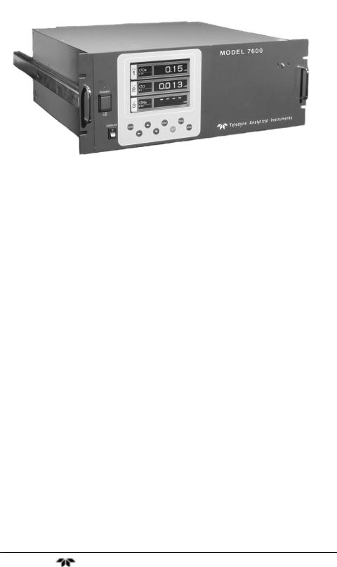
The Model 7600 Infrared Gas Analyzer is a microprocessor based infrared gas analyzer used to measure the concentration of NO, SO2, CO2, CO and CH4 contained in sample gas. It is based on the principle that different molecular species have unique absorption spectrum in the infrared, and the intensity of absorption is determined by the LambertBeer law.
In addition to the infrared analyzer, the Model 7600 can also be equipped with a built-in compact paramagnetic O2 sensor or employ an external zirconia oxygen sensor to increase to 5 the number of simultaneous component species the unit can analyze.
Teledyne's Series 7600 Infrared (IR) Gas Analyzer is conveniently packaged in either a 19" rack mount or NEMA-4 wall mount enclosure. The NEMA-4 enclosure can be X or Z-purged to satisfy hazardous area installation requirements.
A high-sensitivity mass flow type twin detector is used for infrared measurements. By utilizing a single beam, double path design in conjunction with a serial dual-layer transmission detector, the Series 7600 delivers long term, drift-free performance.
The concentration of the desired gases is displayed on a large, easy- to-read back-lit LCD. Figure 1-1 shows the standard rack mountable Model 7600. The user interface is very intuitive and the menu / mode selection buttons, which are readily accessible, provide the operator with dynamic control and extensive diagnostic capabilities.
1.2 Main Features of the Analyzer
The Model 7600 Infrared Gas Analyzer is designed for accurate and reliable gas analysis and is easy to operate. The following features are standard on the 7600 instrument:
Teledyne Analytical Instruments |
15 |
Introduction |
Model 7600 |
|
|
|
|
|
|
|
Figure 1-1: Model 7600A Infrared Gas Analyzer
•Simultaneous measurement of up to five components
•Excellent long-term stability
•Large, easy to read LCD display showing all simultaneous measurements and computations
•Slide-out, chassis design to facilitate any optical or maintenance adjustments required to fine tune analyzer performance (7600A)
•Multiple, in-depth on-screen analyzer functions easily accessible using the front-panel user interface buttons
•Follow & Hold output signal control (during calibration)
•Remote range change control
•Low / Hi limit alarms
•Range ID signals
•Auto-calibration with user adjustable frequency and gas flow time setting programming capabilities
•Remote auto-calibration initiation
•Auto-calibration status contacts
Teledyne Analytical Instruments |
16 |

Infrared Gas Analyzer |
Introduction |
|
|
|
|
|
|
|
•Instrument or calibration error contact outputs
•Extra functions included such as average value computation, O2 conversion
•Pump ON/OFF contact
1.3Options Available
•Percent O2 detector — Paramagnetic (built-in) or ZrO2 (externally installed), user preference
•O2 correction (the conversion of measured CO and SO2 readings into values at standard O2 concentration). Consult factory for more detail for this function.
•Communication functions:
•RS-232C (9 pins D-Sub connector)
•Half-duplex bit serial
•Modbus protocol
1.4Applications
The Model 7600 Infrared Gas Analyzer is a versatile analytical instrument tool and is ideally suited for multi-parameter gas analysis requirements for applications such as:
•Combustion control within the power, pulp and paper, steel, and cement industries
•Heat treating / Inert gas blanketing atmosphere control
•Bulk-gas impurity analysis within the air separation industry
•Anaerobic digester / Bio-gas / Land-fill gas analysis
•Vent gas analysis of oxyhydrochlorination reactors (EDC)
•Off-gas analysis on PTA and Maleic Anhydride reactors
•Fluid Catalytic Cracker (FCC) regeneration gas analysis
•Ammonia / Fertilizer process gas stream analysis
•Continuous Emissions Monitoring Systems (CEMS)
Teledyne Analytical Instruments |
17 |

Introduction |
Model 7600 |
|
|
|
|
|
|
|
•Biochemistry and fermentation,
•Automotive emission analysis
•Explosive and toxic gas analysis
•Chemical analysis
•Refinery operation
•Research applications
1.5Description of the Main Unit
Teledyne's Series 7600 Infrared Gas Analyzer measures the concentration of NO, SO2, CO2, CO, and CH4 in a gas mixture on a continuous basis. The Series 7600 can also be supplied with an oxygen sensor, which allows the simultaneous measurement of oxygen concentration as well. The NEMA-4 enclosure can be X or Z-purged to satisfy hazardous area installation requirements.
The system uses a high-sensitivity mass flow type twin detector for infrared measurements. A single beam, double path optical bench is installed in conjunction with a serial dual-layer transmission detector.
The concentration of the desired gases is displayed on a large, easy- to-read backlit LCD. The user interface is very intuitive and the menu / mode selection buttons, which are readily accessible, provide the operator with dynamic control and extensive diagnostic capabilities. See Figure 1-2.
The front panel mounted power switch turns the instrument on and off while the display switch controls power to the display.
Front panel mounted handles make sliding the instrument out of the panel rack or enclosure a simple task for easy maintenance.
Teledyne Analytical Instruments |
18 |
Infrared Gas Analyzer |
Introduction |
|
|
|
|
|
|
|
Figure 1-2: Model 7600 Description
Gas connections for the 7600 instrument are made on the rear panel of the instrument using the ¼” NPT fittings installed. The standard instrument has two measuring units and a pair of inlet/outlet gas connections exist for each unit. See Section 2.5 Gas Connections.
A power receptacle on the rear panel accepts the three-prong power cable supplied with the instrument. The Model 7600 operates on 100240 VAC 50/60 Hz power. The power inlet conforms to EN60320 Protection Class 1 specifications.
Teledyne Analytical Instruments |
19 |

Introduction |
Model 7600 |
|
|
|
|
|
|
|
Teledyne Analytical Instruments |
20 |
Infrared Gas Analyzer |
Installation |
|
|
|
|
|
|
|
Installation
Installation of the analyzer includes:
1.Unpacking the system.
2.Choosing a suitable location
3.Mounting the analyzer
4.Mounting the terminal module
5.Installing gas connections
6.Making electrical connections
7.Testing the installation.
CAUTION: READ THIS CHAPTER IN ITS ENTIRETY BEFORE INSTALLING THE SYSTEM.
FOR INDOOR USE ONLY.
2.1 Unpacking the Analyzer
The Model 7600 Infrared Gas Analyzer is shipped with the following components:
•7600 Analyzer
•Input/Output terminal module set
•Connection cable
•Power cable
•Fuse (2)
•Cell window mounting tool
•Slide rail (2)*
•Relay board for auto calibration*
•Relay board connection cable*
•Instruction manual
Teledyne Analytical Instruments |
21 |

Installation |
Model 7600 |
|
|
|
|
|
|
|
* These optional items are included if specified at the time of purchase
As soon as you receive the instrument, carefully unpack and inspect the analyzer and components for damage. Immediately report any damage to the shipping agent. The analyzer is shipped with all the materials you need to install and prepare the system for operation.
2.2 Choosing a Location
CAUTION: THIS UNIT IS NOT EXPLOSION-PROOF. DO NOT INSTALL IT IN A LOCATION WHERE EXPLOSIVE OR FLAMMABLE GASES ARE PRESENT.
Select an installation location that meets the following criteria:
•This instrument should be rack mounted, or mounted in a steel enclosure.
•Indoor location.
•Vibration-free.
•Not exposed to direct sunlight.
•Clean and non-cluttered space.
•Depending on the options selected at the time of purchase, the model 7600 requires an AC power source of 100V to 240V AC.
•Operating voltage: 85V to 264V AC
•Rated frequency: 50/60 Hz
•Power consumption: 250 VA max.
•Plug: Comformity to EN60320 class I type 3-pin inlet
•Operation conditions:
•Ambient temperature: -5° to 45°C
•Ambient humidity: 90 % RH or less, no condensation
Teledyne Analytical Instruments |
22 |
Infrared Gas Analyzer |
Installation |
|
|
|
|
|
|
|
2.3 Mounting the Analyzer
The 19” rack mountable 7600 analyzer is designed for either a guide rail or slide rail mounting within a rack or cabinet. The guide rail method supports the weight of the instrument from the bottom and can be used when there is adequate space for removing the top cover for maintenance. The slide rail mount supports the instrument from sliders mounted on the side of the instrument as shown in Figure 2-1. The instrument is then able to slide out of the rack or enclosure for required access during maintenance.
Figure 2-1: Slide Rail Mounting Dimensions
2.4 Mounting the Input/Output Terminal Module
The input/output module is the electronic interface that handles the various signals to and from the analyzer. It consists of up to five terminal blocks, a communications connector, a cable connector, and a solenoid drive output connector mounted together on a single mounting plate. See Figure 2-2.
Mount the input/output terminal module to the rack or cabinet panel using the six M4 screws supplied. For grounding, see Figure 2-3.
Note: To avoid noise generated from external units, mount the I/O terminal module mounting plate to the panel making sure there is adequate metal contact for continuity at the
Teledyne Analytical Instruments |
23 |

Installation |
Model 7600 |
|
|
|
|
|
|
|
mounting surface. Connect the panel to the same ground as the analyzer main unit.
Figure 2-2: Input/Output Terminal Module
Figure 2-3: Mounting the I/O Module
Teledyne Analytical Instruments |
24 |

Infrared Gas Analyzer |
Installation |
|
|
|
|
|
|
|
2.5 Gas Connections
Gas connections are made on the rear panel of the analyzer. Adhere to the following guidelines when making gas connections:
•Use a corrosion resistant tube such as Teflon, stainless or polyethylene to connect the instrument to a sampling system. Even if there is a danger of corrosion, refrain from using rubber or soft vinyl tubing. This would result in instrument inaccuracies due to gas absorption by the piping materials.
•Pipe connection port is Rc1/4 female thread (or NPT1/4). Piping should be cut as short as possible for quicker response. About 4 mm inner diameter is recommended.
•Keep out dust and debris from the tubing and connections . Always use clean tubing and fittings.
Connect the gas tube as follows:
•Sample gas inlet: Attach the sample gas tube to the inlet fitting. The sample gas should be filtered and dehumidified before passing into the analyzer. This port is also used to connect the zero and span calibration gases.
•The gas flow should be constant within the range of 0.5 L/min ±0.2 L/min.
•Sample gas outlet: Sample gas exits the analyzer through the gas out port at atmospheric pressure. Exhaust gases must be vented safely.
•Purge gas inlet: This connection is used for purging the inside of the analyzer. Purging is not always required. See Section 2.5.6 Purging the Analyzer. When required, use dry
N2 or instrumentation air for the purge gas. Use a flow rate of 1L/min or greater).
2.5.1Internal Piping Diagram
Note: When the purge gas inlet is provided, an internal connection to measuring unit 2 is installed.
Teledyne Analytical Instruments |
25 |
Installation |
Model 7600 |
|
|
|
|
|
|
|
An internal piping diagram for an instrument with one or two measuring units is shown in Figure 2-4. When there are two measuring units, if a built-in oxygen sensor is used, it must be installed in measuring unit 2. The diagram shows the combination of two cells used in measuring unit #2. This is possible by combining ranges. When a single measuring unit is used, there is only a single inlet and outlet gas connection.
Figure 2-4: Internal Piping with Single or Dual Measuring Units
Depending on the options chosen, the analyzer can be configured in several ways. Table 2-1 lists the possible configurations for single and dual measuring units with 1 to 4 component meters.
Teledyne Analytical Instruments |
26 |
Infrared Gas Analyzer |
Installation |
|
|
|
|
|
|
|
Table 2-1: Correspondence of Measured Components and Measuring
Units
Measuring components |
Measuring unit 1 |
Measuring unit 2 |
|
|
|
1-component meter for NO, |
Each component |
None |
SO2, CO2, CO and CH4 |
|
|
2-component meter for |
NO/SO2 |
None |
NO/SO2 and CO2/CO |
CO2/CO |
|
2-component meter for |
NO |
CO |
NO/CO |
|
|
3-component meter for |
NO/SO2 |
CO |
NO/SO2/CO |
|
|
4-component meter for |
NO/SO2 |
CO2/CO |
NO/SO2/CO2/CO |
|
|
2.5.2 External Piping Diagram
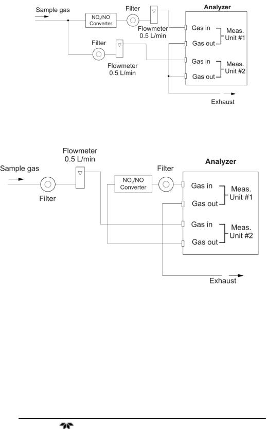
There are several ways to bring sample gas to the analyzer depending on the number of inlet/outlet gas connections on your instrument Recommended piping diagrams are shown in Figures 2-5, 2- 6 and 2-7. Figure 2-5 is a schematic for an instrument with a single pair of inlet/outlet gas connections. Figures 2-6 and 2-7 are used when there are two pair of inlet/outlet connections. Note that a NO2/NO converter is used when NO measurement is used for NOx analysis.
Figure 2-5: External Piping with Single Inlet and Outlet
Teledyne Analytical Instruments |
27 |
Installation |
Model 7600 |
|
|
|
|
|
|
|
Figure 2-6: External Piping with Two Pair of Inlet/Outlet (1)
Figure 2-7: External Piping with Two Pair of Inlet/Outlet (2)
2.5.3 Gas Conditioning
For optimum performance, the sample gas should be treated as follows:
•A filter should be installed to remove any dust or particles in the sample gas. For a final stage filter, use a filter that can remove dust particles of 0.3 μm.
Teledyne Analytical Instruments |
28 |

Infrared Gas Analyzer |
Installation |
|
|
|
|
|
|
|
•The dew point of the sample gas must be lower than the ambient temperature to avoid condensation in the analyzer. If vapor is contained in the sampling gas, the dew point should be lowered to 0°C by using a dehumidifier.
•If SO2 mist is contained in the sample gas, use a mist filter or cooler to remove the SO2 mist. Other mists should be removed by using an appropriate mist filter or cooler.
•Corrosive gases such as Cl2, F2 and HCl, if contained in the sample gas in considerable amounts, will shorten the life of the instrument.
•Sample gas temperature should be within 0 to 50°C. Hot gas should not be fed directly into the instrument.
2.5.4Flowrate
Use a flowrate of 0.5L/min ±0.2L/min. The sample system should be designed to avoid any flow fluctuation during measurement.
Use a flowmeter to observe the flow reading as shown in the external piping diagrams of Figures 2.5, 2.6 and 2.7.
2.5.5 Preparation of Calibration Gas
Routine calibration using calibration gases is required for optimizing the performance of this instrument. Once a week is a suggested calibration frequency. Table 2-2 indicates the zero and span gas required for calibration.
Table 2-2: Zero and Span Gas
|
Analyzer without |
Analyzer with built-in |
Analyzer with external |
|
O2 |
O2 |
zirconia O2 sensor |
Zero gas |
N2 gas |
N2 gas |
Dry air |
|
|
|
|
Span gas |
Gas concentration |
Gas concentration of |
Gas concentration of 90% |
other than for |
of 90% or more of |
90% or more of full |
or more of full scale |
O2 |
full scale |
scale |
|
t |
|
Gas concentration of |
1 to 2% O2 |
Span gas for |
NA |
||
O2 analysis |
90% or more of full |
|
|
|
|
scale |
|
Teledyne Analytical Instruments |
29 |

Installation |
Model 7600 |
|
|
|
|
|
|
|
2.5.6 Purging the Analyzer
In general, purging the analyzer is not required unless one of the following cases apply:
•A combustible gas component is contained in sample gas.
•Corrosive gas is contained in the atmospheric air at the installation site.
•The same gas as the sample gas component is contained in the atmospheric air at the installation site.
In the above situations, the inside of analyzer should be purged with instrument air or N2. Use a purge flow rate of about 1 L/min.
Use a filter to remove dust or mist from the purge gas.
2.5.7 Sample Gas Pressure
The sample gas pressure at the outlet should be atmospheric pressure.
2.5.8 Example configuration of gas sampling system
A typical system configuration with five component gas analysis for monitoring combustion exhaust gas from boiler, refuse incinerator, etc. is shown in Figure 2-8. Contact Teledyne for specific application system configuration or further information.
The system shown is comprised of:
•Model 7600—with dual measuring unit option and external zirconia oxygen sensor.
•Gas Extractor—with stainless steel filter of standard mesh 40 μm equipped with integral heater.
•Mist Filter—to remove condensate, mist and dust from the sample before it enters the analyzer.
•Safety Drain Trap—with two compartments for positive and negative pressure. It monitors and adjusts the sample gas pressure.
•Gas Aspirator—to aspirate the sample gas.
•Electronic Gas Cooler—used to dry the sample gas to a dew point of approximately 2°C (35.6°F).
Teledyne Analytical Instruments |
30 |
 Loading...