


 Loading...
TDP0500 & TDP1000
500 MHz & 1 GHz High Voltage Differential Probes Quick Start User Manual
www.tektronix.com
071-1974-00

Copyright © Tektronix. All rights reserved. Licensed software products are owned by Tektronix or its subsidiaries or suppliers, and are protected by national copyright laws and international treaty provisions.
Tektronix products are covered by U.S. and foreign patents, issued and pending. Information in this publication supersedes that in all previously published material. Specifications and price change privileges reserved.
TEKTRONIX and TEK are registered trademarks of Tektronix, Inc.
KlipChip, TekVPI, and TwinFoot are trademarks of Tektronix, Inc.
TwinTip is a registered trademark of Tektronix, Inc.
Contacting Tektronix
Tektronix, Inc.
14200 SW Karl Braun Drive
P.O. Box 500
Beaverton, OR 97077
USA
For product information, sales, service, and technical support:
In North America, call 1-800-833-9200.
Worldwide, visit www.tektronix.com to find contacts in your area.
Warranty 2
Tektronix warrants that this product will be free from defects in materials and workmanship for a period of one (1) year from the date of shipment. If any such product proves defective during this warranty period, Tektronix, at its option, either will repair the defective product without charge for parts and labor, or will provide a replacement in exchange for the defective product. Parts, modules and replacement products used by Tektronix for warranty work may be new or reconditioned to like new performance. All replaced parts, modules and products become the property of Tektronix.
In order to obtain service under this warranty, Customer must notify Tektronix of the defect before the expiration of the warranty period and make suitable arrangements for the performance of service. Customer shall be responsible for packaging and shipping the defective product to the service center designated by Tektronix, with shipping charges prepaid. Tektronix shall pay for the return of the product to Customer if the shipment is to a location within the country in which the Tektronix service center is located. Customer shall be responsible for paying all shipping charges, duties, taxes, and any other charges for products returned to any other locations.
This warranty shall not apply to any defect, failure or damage caused by improper use or improper or inadequate maintenance and care. Tektronix shall not be obligated to furnish service under this warranty a) to repair damage resulting from attempts by personnel other than Tektronix representatives to install, repair or service the product; b) to repair damage resulting from improper use or connection to incompatible equipment; c) to repair any damage or malfunction caused by the use of non-Tektronix supplies; or d) to service a product that has been modified or integrated with other products when the effect of such modification or integration increases the time or difficulty of servicing the product.
THIS WARRANTY IS GIVEN BY TEKTRONIX WITH RESPECT TO THE PRODUCT IN LIEU OF ANY OTHER WARRANTIES, EXPRESS OR IMPLIED. TEKTRONIX AND ITS VENDORS DISCLAIM ANY IMPLIED WARRANTIES OF MERCHANTABILITY OR FITNESS FOR A PARTICULAR PURPOSE. TEKTRONIX’ RESPONSIBILITY TO REPAIR OR REPLACE DEFECTIVE PRODUCTS IS THE SOLE AND EXCLUSIVE REMEDY PROVIDED TO THE CUSTOMER FOR BREACH OF THIS WARRANTY. TEKTRONIX AND ITS VENDORS WILL NOT BE LIABLE FOR ANY INDIRECT, SPECIAL, INCIDENTAL, OR CONSEQUENTIAL DAMAGES IRRESPECTIVE OF WHETHER TEKTRONIX OR THE VENDOR HAS ADVANCE NOTICE OF THE POSSIBILITY OF SUCH DAMAGES.

|
Table of Contents |
Table of Contents |
|
General Safety Summary . . .. . . . . . . . . . . . . . . . . . . . . . . . . . . . . . . . . . . . . . . . . . . . . . . . . . . . . . . . . . . . . . . . . . . . . . . . . . . . . . . . . . . . . . . . . . . . . . . . . |
. . . . . . . . . . . . . . iii |
Environmental Considerations . . . . . . . . . . . . . . . . . . . . . . . . . . . . . . . . . . . . . . . . . . . . . . . . . . . . . . . . . . . . . . . . . . . . . . . . . . . . . . . . . . . . . . . . . . . . . . . . |
. . . .. . . . . . . . . vi |
Preface. . . . . . . . . . . . . . . . . . . . . . . . . . . . . . . . . . . . . . . . . . . . . . . . . . . . . . . . . . . . . . . . . . . . . . . . . . . . . . . . . . . . . . . . . . . . . . . . . . . . . . . . . . . . . . . . . . . . . . . .. |
. . . . . . . . . . . . viii |
Documentation . . . . . . . . . . . . . . . . . . . . . . . . . . . . . . . . . . . . . . . . . . . . . . . . . . . . . . . . . . . . . . . . . . . . . . . . . . . . . . . . . . . . . . . . . . . . . . . . . . . . . . . . . . . |
. . . . . . .. . . . . viii |
Conventions Used in this Manual . . . . . . . . . . . . . . . . . . . . . . . . . . . . . . . . . . . . . . . . . . . . . . . . . . . . . . . . . . . . . . . . . . . . . . . . . . . . . . . . . . . . . . . |
. . . . . . . . . . . . viii |
Returning the Probe for Servicing . . . . . . . . . . . . . . . . . . . . . . . . . . . . . . . . . . . . . . . . . . . . . . . . . . . . . . . . . . . . . . . . . . . . . . . . . . . . . . . . . . . . . . . |
. . . . . . . . . . .. . ix |
Key Features . . . . . . . . . . . . . . . . . . . . . . . . . . . . . . . . . . . . . . . . . . . . . . . . . . . . . . . . . . . . . . . . . . . . . . . . . . . . . . . . . . . . . . . . . . . . . . . . . . . . . . . . . . . . . . . . . . |
. .. . . . . . . . . . . 1 |
Operating Considerations . . . . . . . . . . . . . . . . . . . . . . . . . . . . . . . . . . . . . . . . . . . . . . . . . . . . . . . . . . . . . . . . . . . . . . . . . . . . . . . . . . . . . . . . . . . . . . . . . . . . . |
. . .. . . . . . . . . . 2 |
Installation . . . . . . . . . . . . . . . . . . . . . . . . . . . . . . . . . . . . . . . . . . . . . . . . . . . . . . . . . . . . . . . . . . . . . . . . . . . . . . . . . . . . . . . . . . . . . . . . . . . . . . . . . . . . . . . . . . .. . |
. . . . . . . . . . . . . 4 |
Connecting to the Host Instrument . . . . . . . . . . . . . . . . . . . . . . . . . . . . . . . . . . . . . . . . . . . . . . . . . . . . . . . . . . . . . . . . . . . . . . . . . . . . . . . . . . . . . . |
. . . . . . . . . . . . . 4 |
Probe Controls and Indicators . . . . . . . . . . . . . . . . . . . . . . . . . . . . . . . . . . . . . . . . . . . . . . . . . . . . . . . . . . . . . . . . . . . . . . . . . . . . . . . . . . . . . . . . . . . |
. . . . . . . . . .. . . 5 |
Functional Check . . . . . . . . . . . . . . . . . . . . . . . . . . . . . . . . . . . . . . . . . . . . . . . . . . . . . . . . . . . . . . . . . . . . . . . . . . . . . . . . . . . . . . . . . . . . . . . . . . . . . . . . . . . . . . |
. .. . . . . . . . . . . 9 |
Required Equipment . . . . . . . . . . . . . . . . . . . . . . . . . . . . . . . . . . . . . . . . . . . . . . . . . . . . . . . . . . . . . . . . . . . . . . . . . . . . . . . . . . . . . . . . . . . . . . . . . . . . . |
. . . . . . . . .. . . . 9 |
Calibration . . . . . . . . . . . . . . . . . . . . . . . . . . . . . . . . . . . . . . . . . . . . . . . . . . . . . . . . . . . . . . . . . . . . . . . . . . . . . . . . . . . . . . . . . . . . . . . . . . . . . . . . . . . . . . . . . . . .. |
. . . . . . . . . . . . 11 |
Prerequisites . . . . . . . . . . . . . . . . . . . . . . . . . . . . . . . . . . . . . . . . . . . . . . . . . . . . . . . . . . . . . . . . . . . . . . . . . . . . . . . . . . . . . . . . . . . . . . . . . . . . . . . . . . . . . |
. . . . .. . . . . . . 11 |
Required Equipment . . . . . . . . . . . . . . . . . . . . . . . . . . . . . . . . . . . . . . . . . . . . . . . . . . . . . . . . . . . . . . . . . . . . . . . . . . . . . . . . . . . . . . . . . . . . . . . . . . . . . |
. . . . . . . . .. . . 11 |
Test Procedure . . . . . . . . . . . . . . . . . . . . . . . . . . . . . . . . . . . . . . . . . . . . . . . . . . . . . . . . . . . . . . . . . . . . . . . . . . . . . . . . . . . . . . . . . . . . . . . . . . . . . . . . . . . |
. . . . . . .. . . . . 12 |
Basic Operation. . . . . . . . . . . . . . . . . . . . . . . . . . . . . . . . . . . . . . . . . . . . . . . . . . . . . . . . . . . . . . . . . . . . . . . . . . . . . . . . . . . . . . . . . . . . . . . . . . . . . . . . . . . . . . . . |
.. . . . . . . . . . . 15 |
Probe Head Assembly . . . . . . . . . . . . . . . . . . . . . . . . . . . . . . . . . . . . . . . . . . . . . . . . . . . . . . . . . . . . . . . . . . . . . . . . . . . . . . . . . . . . . . . . . . . . . . . . . . . |
. . . . . . . . . . .. 15 |
TDP0500 & TDP1000 Quick Start User Manual |
i |

Table of Contents |
|
Probe Input. . . . . . . . . . . . . . . . . . . . . . . . . . . . . . . . . . . . . . . . . . . . . . . . . . . . . . . . . . . . . . . . . . . . . . . . . . . . . . . . . . . . . . . . . . . . . . . . . . . . . . . . . . . . . . . . . . . . .. . . . . . |
16 |
Probe Offset and AutoZero . . . . . . . . . . . . . . . . . . . . . . . . . . . . . . . . . . . . . . . . . . . . . . . . . . . . . . . . . . . . . . . . . . . . . . . . . . . . . . . . . . . . . . . . . . . . . . . . . . . . . . . . .. |
19 |
Applications . . . . . . . . . . . . . . . . . . . . . . . . . . . . . . . . . . . . . . . . . . . . . . . . . . . . . . . . . . . . . . . . . . . . . . . . . . . . . . . . . . . . . . . . . . . . . . . . . . . . . . . . . . . . . . . . . . .. . . . . . . . . . . . . |
23 |
Accessories and Options . . . . . . . . . . . . . . . . . . . . . . . . . . . . . . . . . . . . . . . . . . . . . . . . . . . . . . . . . . . . . . . . . . . . . . . . . . . . . . . . . . . . . . . . . . . . . . . . . . . . . . . . . .. . . . . . . . |
27 |
Using Standard Accessories . . .. . . . . . . . . . . . . . . . . . . . . . . . . . . . . . . . . . . . . . . . . . . . . . . . . . . . . . . . . . . . . . . . . . . . . . . . . . . . . . . . . . . . . . . . . . . . . . . . . . . . . |
27 |
Optional Accessories . . . . . . . . . . . . . . . . . . . . . . . . . . . . . . . . . . . . . . . . . . . . . . . . . . . . . . . . . . . . . . . . . . . . . . . . . . . . . . . . . . . . . . . . . . . . . . . . . . . . . . . . . . . .. . . . |
37 |
Options . . . . . . . . . . . . . . . . . . . . . . . . . . . . . . . . . . . . . . . . . . . . . . . . . . . . . . . . . . . . . . . . . . . . . . . . . . . . . . . . . . . . . . . . . . . . . . . . . . . . . . . . . . . . . . . . . . . . . . . .. . . . . . . |
42 |
Probing Principles . . . . . . . . . . . . . . . . . . . . . . . . . . . . . . . . . . . . . . . . . . . . . . . . . . . . . . . . . . . . . . . . . . . . . . . . . . . . . . . . . . . . . . . . . . . . . . . . . . . . . . . . . . . . . .. . . . . . . . . . . |
43 |
Probe Grounding. . .. . . . . . . . . . . . . . . . . . . . . . . . . . . . . . . . . . . . . . . . . . . . . . . . . . . . . . . . . . . . . . . . . . . . . . . . . . . . . . . . . . . . . . . . . . . . . . . . . . . . . . . . . . . . . . . . . . |
43 |
Input Impedance and Probe Loading. . .. . . . . . . . . . . . . . . . . . . . . . . . . . . . . . . . . . . . . . . . . . . . . . . . . . . . . . . . . . . . . . . . . . . . . . . . . . . . . . . . . . . . . . . . . . . . . |
44 |
Maintenance . . . . . . . . . . . . . . . . . . . . . . . . . . . . . . . . . . . . . . . . . . . . . . . . . . . . . . . . . . . . . . . . . . . . . . . . . . . . . . . . . . . . . . . . . . . . . . . . . . . . . . . . . . . . . . . . . . . .. . . . . . . . . . . |
45 |
Host Instrument Firmware . . . . . . . . . . . . . . . . . . . . . . . . . . . . . . . . . . . . . . . . . . . . . . . . . . . . . . . . . . . . . . . . . . . . . . . . . . . . . . . . . . . . . . . . . . . . . . . . . . . . . . . . .. . |
45 |
Error Condition . . . . . . . . . . . . . . . . . . . . . . . . . . . . . . . . . . . . . . . . . . . . . . . . . . . . . . . . . . . . . . . . . . . . . . . . . . . . . . . . . . . . . . . . . . . . . . . . . . . . . . . . . . . . . . . . .. . . . . . |
45 |
Replacement Parts . . . . . . . . . . . . . . . . . . . . . . . . . . . . . . . . . . . . . . . . . . . . . . . . . . . . . . . . . . . . . . . . . . . . . . . . . . . . . . . . . . . . . . . . . . . . . . . . . . . . . . . . . . . . . . .. . . |
46 |
Cleaning. . . . . . . . . . . . . . . . . . . . . . . . . . . . . . . . . . . . . . . . . . . . . . . . . . . . . . . . . . . . . . . . . . . . . . . . . . . . . . . . . . . . . . . . . . . . . . . . . . . . . . . . . . . . . . . . . . . . . . .. . . . . . . |
46 |
Index |
|
ii |
TDP0500 & TDP1000 Quick Start User Manual |

General Safety Summary
General Safety Summary
Review the following safety precautions to avoid injury and prevent damage to this product or any products connected to it. To avoid potential hazards, use this product only as specified.
Only qualified personnel should perform service procedures.
While using this product, you may need to access other parts of a larger system. Read the safety sections of the other component manuals for warnings and cautions related to operating the system.
To Avoid Fire or Personal Injury
Connect and Disconnect Properly. Do not connect or disconnect probes or test leads while they are connected to a voltage source.
Ground the Product. This product is indirectly grounded through the grounding conductor of the mainframe power cord. To avoid electric shock, the grounding conductor must be connected to earth ground. Before making connections to the input or output terminals of the product, ensure that the product is properly grounded.
Observe All Terminal Ratings. To avoid fire or shock hazard, observe all ratings and markings on the product. Consult the product manual for further ratings information before making connections to the product.
Connect the probe reference lead to earth ground only.
Do not apply a potential to any terminal, including the common terminal, that exceeds the maximum rating of that terminal. Do Not Operate Without Covers. Do not operate this product with covers or panels removed.
Do Not Operate With Suspected Failures. If you suspect that there is damage to this product, have it inspected by qualified service personnel.
TDP0500 & TDP1000 Quick Start User Manual |
iii |

General Safety Summary
Avoid Exposed Circuitry. Do not touch exposed connections and components when power is present.
Do Not Operate in Wet/Damp Conditions.
Do Not Operate in an Explosive Atmosphere.
Keep Product Surfaces Clean and Dry.
Terms in this Manual
These terms may appear in this manual:
WARNING. Warning statements identify conditions or practices that could result in injury or loss of life.
CAUTION. Caution statements identify conditions or practices that could result in damage to this product or other property.
|
Symbols and Terms on the Product |
|
These terms may appear on the product: |
|
DANGER indicates an injury hazard immediately accessible as you read the marking. |
|
WARNING indicates an injury hazard not immediately accessible as you read the marking. |
|
CAUTION indicates a hazard to property including the product. |
iv |
TDP0500 & TDP1000 Quick Start User Manual |

General Safety Summary
The following symbols may appear on the product:
TDP0500 & TDP1000 Quick Start User Manual |
v |

Environmental Considerations
Environmental Considerations
This section provides information about the environmental impact of the product.
Product End-of-Life Handling
Observe the following guidelines when recycling an instrument or component:
Equipment Recycling. Production of this equipment required the extraction and use of natural resources. The equipment may contain substances that could be harmful to the environment or human health if improperly handled at the product’s end of life. In order to avoid release of such substances into the environment and to reduce the use of natural resources, we encourage you to recycle this product in an appropriate system that will ensure that most of the materials are reused or recycled appropriately.
The symbol shown below indicates that this product complies with the European Union’s requirements according to Directive 2002/96/EC on waste electrical and electronic equipment (WEEE). For information about recycling options, check the Support/Service section of the Tektronix Web site (www.tektronix.com).
vi |
TDP0500 & TDP1000 Quick Start User Manual |
Environmental Considerations
Restriction of Hazardous Substances
This product has been classified as Monitoring and Control equipment, and is outside the scope of the 2002/95/EC RoHS Directive. This product is known to contain lead, cadmium, mercury, and hexavalent chromium.
TDP0500 & TDP1000 Quick Start User Manual |
vii |

Preface
Preface
This manual describes the installation and operation of the TDP0500 and TDP1000 High Voltage Differential probes. Basic probe operations and concepts are presented in this manual. You can also check the Tektronix Web site for this document and other related information.
Documentation
To read about |
Read these documents * |
First Time Operation, Functional Check, Operating Basics |
This Manual. |
Specifications, Performance Verification |
The Technical Reference Manual. |
In-depth oscilloscope operation, user interface, GPIB commands |
The online help (from the Help menu on the |
|
host instrument). |
*To access the documentation that is installed on your instrument, click Start in the taskbar and select Programs > TekApplications.
Conventions Used in this Manual
The following icon is used throughout this manual to indicate a step sequence.
viii |
TDP0500 & TDP1000 Quick Start User Manual |

Preface
Returning the Probe for Servicing
If your probe requires servicing, you must return the probe to Tektronix. If the original packaging is unfit for use or not available, use the following packaging guidelines:
Preparation for Shipment
1.Use a corrugated cardboard shipping carton having inside dimensions at least one inch greater than the probe
dimensions. The box should have a carton test strength of at least 200 pounds.
2.Put the probe into an antistatic bag or wrap it to protect it from dampness.
3.Place the probe into the box and stabilize it with light packing material.
4.Seal the carton with shipping tape.
5.Refer to Contacting Tektronix at the beginning of this manual for the shipping address.
TDP0500 & TDP1000 Quick Start User Manual |
ix |

Preface
x |
TDP0500 & TDP1000 Quick Start User Manual |
Key Features
Key Features
The TDP0500 and TDP1000 High Voltage Differential probes enable you to make accurate differential measurements from DC to 500 MHz (TDP0500), or 1 GHz (TDP1000), using oscilloscopes featuring the new Tektronix TekVPI oscilloscope interface.
Key features include:
DC to 500 MHz bandwidth (TDP0500) or 1 GHz (TDP1000)
Selectable ±42 V or ±4.25 V (DC + peak AC) differential input voltage ranges
±42 V DC offset range
100 Hz, 10 kHz, 1 MHz, and Full bandwidth limiting filters
1 MΩ differential input resistance
<1 pF differential input capacitance
>18 dB CMRR @ 250 MHz (42 V range)
Provides automatic units scaling on the oscilloscope display
Large-signal performance verification capability
TDP0500 & TDP1000 Quick Start User Manual |
1 |

Operating Considerations
Operating Considerations
Table 1: TDP0500 & TDP1000
Characteristic |
Description |
Input Voltage |
Differential: |
|
±4.25 V (DC + peak AC), 3 V RMS |
|
±42 V (DC + peak AC), 30 V RMS |
|
Common Mode: |
|
±35 V (DC + peak AC), 25 V RMS (Both ranges; input referenced to ground) |
Temperature |
Operating: 0 to +40 °C (+32 °F to +104 °F) |
|
Nonoperating: -55 °C to +75 °C (-67 °F to +167 °F) |
Humidity |
Operating: +30 °C to +40 °C (+86 °F to +104 °F) 0-90% RH |
|
Nonoperating: +30 °C to +60 °C (+86 °F to +140 °F) 0-90% RH |
Altitude |
Operating: Up to 3000 meters (10,000 feet) |
|
Nonoperating: Up to 12192 meters (40,000 feet) |
Pollution Degree |
2, Indoor use only |
2 |
TDP0500 & TDP1000 Quick Start User Manual |
Operating Considerations
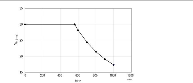
Figure 1: Voltage versus frequency derating curve
TDP0500 & TDP1000 Quick Start User Manual |
3 |
Installation
Installation
Connecting to the Host Instrument
WARNING. Your TekVPI instrument may require a firmware upgrade to support full functionality of the TDP0500 and TDP1000 probes. Before you connect the probe, check the version requirements. (See page 45, Host Instrument Firmware.)
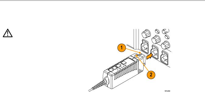
1.Slide the probe into the TekVPI receptacle. The probe snaps when fully engaged.
When you connect the probe, the host instrument reads information from the probe and identifies the probe type.
2.To disconnect, press the latch release button and pull away from the instrument.
4 |
TDP0500 & TDP1000 Quick Start User Manual |

Installation
Probe Controls and Indicators
Range Button and LEDs
When the probe is powered on, all LEDs briefly light during the power-on self test routine, and then one of the Range LEDs remains lit. This indicates that the probe is in normal operating mode.
Press the Range button to toggle the range selection. The corresponding LED lights to indicate the selected range.
NOTE. The host instrument sets all probe settings to the last known state for the probe/channel combination. If none of the Range LEDs are lit, the instrument may have detected an error condition. Disconnect and reconnect the probe to clear the error.
TDP0500 & TDP1000 Quick Start User Manual |
5 |
Loading...