


Instruction Manual
TCPA300/400 Amplifiers &
TCP300/400 Series AC/DC Current Probes
071-1183-03
This document applies for firmware version 1.0 and above.
Warning
The servicing instructions are for use by qualified personnel only. To avoid personal injury, do not perform any servicing unless you are qualified to do so. Refer to all safety summaries prior to performing service.
www.tektronix.com
Copyright © Tektronix. All rights reserved. Licensed software products are owned by Tektronix or its subsidiaries or suppliers, and are protected by national copyright laws and international treaty provisions.
Tektronix products are covered by U.S. and foreign patents, issued and pending. Information in this publication supercedes that in all previously published material. Specifications and price change privileges reserved.
TEKTRONIX and TEK are registered trademarks of Tektronix, Inc.
Contacting Tektronix
Tektronix, Inc.
14200 SW Karl Braun Drive
P.O. Box 500
Beaverton, OR 97077
USA
For product information, sales, service, and technical support:
HIn North America, call 1-800-833-9200.
HWorldwide, visit www.tektronix.com to find contacts in your area.
Warranty 2
Tektronix warrants that this product will be free from defects in materials and workmanship for a period of one (1) year from the date of shipment. If any such product proves defective during this warranty period, Tektronix, at its option, either will repair the defective product without charge for parts and labor, or will provide a replacement in exchange for the defective product. Parts, modules and replacement products used by Tektronix for warranty work may be new or reconditioned to like new performance. All replaced parts, modules and products become the property of Tektronix.
In order to obtain service under this warranty, Customer must notify Tektronix of the defect before the expiration of the warranty period and make suitable arrangements for the performance of service. Customer shall be responsible for packaging and shipping the defective product to the service center designated by Tektronix, with shipping charges prepaid. Tektronix shall pay for the return of the product to Customer if the shipment is to a location within the country in which the Tektronix service center is located. Customer shall be responsible for paying all shipping charges, duties, taxes, and any other charges for products returned to any other locations.
This warranty shall not apply to any defect, failure or damage caused by improper use or improper or inadequate maintenance and care. Tektronix shall not be obligated to furnish service under this warranty a) to repair damage resulting from attempts by personnel other than Tektronix representatives to install, repair or service the product; b) to repair damage resulting from improper use or connection to incompatible equipment; c) to repair any damage or malfunction caused by the use of non-Tektronix supplies; or d) to service a product that has been modified or integrated with other products when the effect of such modification or integration increases the time or difficulty of servicing the product.
THIS WARRANTY IS GIVEN BY TEKTRONIX WITH RESPECT TO THE PRODUCT IN LIEU OF ANY OTHER WARRANTIES, EXPRESS OR IMPLIED. TEKTRONIX AND ITS VENDORS DISCLAIM ANY IMPLIED WARRANTIES OF MERCHANTABILITY OR FITNESS FOR A PARTICULAR PURPOSE. TEKTRONIX’ RESPONSIBILITY TO REPAIR OR REPLACE DEFECTIVE PRODUCTS IS THE SOLE AND EXCLUSIVE REMEDY PROVIDED TO THE CUSTOMER FOR BREACH OF THIS WARRANTY. TEKTRONIX AND ITS VENDORS WILL NOT BE LIABLE FOR ANY INDIRECT, SPECIAL, INCIDENTAL, OR CONSEQUENTIAL DAMAGES IRRESPECTIVE OF WHETHER TEKTRONIX OR THE VENDOR HAS ADVANCE NOTICE OF THE POSSIBILITY OF SUCH DAMAGES.

Table of Contents
Preface . . . . . . . . . . . . . . . . . . . . . . . . . . . . . . . . . . . . . . . . . . . . . . . . . . . . . . . . |
xv |
Getting Started |
|
System Configuration . . . . . . . . . . . . . . . . . . . . . . . . . . . . . . . . . . . . . . . . . . . . . |
1-1 |
Options . . . . . . . . . . . . . . . . . . . . . . . . . . . . . . . . . . . . . . . . . . . . . . . . . . . . . . . . |
1-3 |
Standard Accessories . . . . . . . . . . . . . . . . . . . . . . . . . . . . . . . . . . . . . . . . . . . . . |
1-4 |
Optional Accessories . . . . . . . . . . . . . . . . . . . . . . . . . . . . . . . . . . . . . . . . . . . . . |
1-5 |
Probe Covers . . . . . . . . . . . . . . . . . . . . . . . . . . . . . . . . . . . . . . . . . . . . . . . . . . . . |
1-6 |
Travel Case . . . . . . . . . . . . . . . . . . . . . . . . . . . . . . . . . . . . . . . . . . . . . . . . . . . . . |
1-7 |
Connecting the Amplifier to an Oscilloscope . . . . . . . . . . . . . . . . . . . . . . . . . . |
1-8 |
Power on the Amplifier . . . . . . . . . . . . . . . . . . . . . . . . . . . . . . . . . . . . . . . . . . . |
1-8 |
Connecting a Current Probe to the Amplifier . . . . . . . . . . . . . . . . . . . . . . . . . . |
1-9 |
Operating the Current Probe Slide . . . . . . . . . . . . . . . . . . . . . . . . . . . . . . . . . . . |
1-10 |
Degaussing and Autobalancing the Current Probe . . . . . . . . . . . . . . . . . . . . . . |
1-11 |
DC Measurements . . . . . . . . . . . . . . . . . . . . . . . . . . . . . . . . . . . . . . . . . . . . . . . |
1-12 |
AC Measurements . . . . . . . . . . . . . . . . . . . . . . . . . . . . . . . . . . . . . . . . . . . . . . . |
1-14 |
Operating Basics |
|
Control Summary . . . . . . . . . . . . . . . . . . . . . . . . . . . . . . . . . . . . . . . . . |
2-1 |
TCPA300 and TCPA400 Controls . . . . . . . . . . . . . . . . . . . . . . . . . . . . . . . . . . . |
2-2 |
PROBE DEGAUSS AUTOBALANCE Button and Indicator . . . . . . . . . . |
2-2 |
MANUAL BALANCE Buttons and Indicator . . . . . . . . . . . . . . . . . . . . . . |
2-3 |
PROBE OPEN Indicator . . . . . . . . . . . . . . . . . . . . . . . . . . . . . . . . . . . . . . . |
2-3 |
OVERLOAD Indicator . . . . . . . . . . . . . . . . . . . . . . . . . . . . . . . . . . . . . . . . |
2-3 |
NOT TERMINATED INTO 50 Ω Indicator . . . . . . . . . . . . . . . . . . . . . . . . |
2-4 |
NONCOMPATIBLE PROBE TYPE Indicator . . . . . . . . . . . . . . . . . . . . . . |
2-4 |
ON/STANDBY Button . . . . . . . . . . . . . . . . . . . . . . . . . . . . . . . . . . . . . . . . |
2-4 |
RANGE Button (TCPA300 only) . . . . . . . . . . . . . . . . . . . . . . . . . . . . . . . . |
2-4 |
COUPLING Button and Indicators . . . . . . . . . . . . . . . . . . . . . . . . . . . . . . . |
2-4 |
PROBE INPUT Connector . . . . . . . . . . . . . . . . . . . . . . . . . . . . . . . . . . . . . |
2-5 |
OUTPUT Connector . . . . . . . . . . . . . . . . . . . . . . . . . . . . . . . . . . . . . . . . . . |
2-5 |
Probe DC Gain Adjust (located on probes) . . . . . . . . . . . . . . . . . . . . . . . . . |
2-5 |
GPIB Operation . . . . . . . . . . . . . . . . . . . . . . . . . . . . . . . . . . . . . . . . . . . . . . |
2-6 |
Reference |
|
Reference Notes . . . . . . . . . . . . . . . . . . . . . . . . . . . . . . . . . . . . . . . . . . . |
3-1 |
Degaussing a Probe with an Unpowered Conductor in the Jaws . . . . . . . . . . . . |
3-1 |
Measuring Differential Current . . . . . . . . . . . . . . . . . . . . . . . . . . . . . . . . . . . . . |
3-2 |
AC and DC Coupling . . . . . . . . . . . . . . . . . . . . . . . . . . . . . . . . . . . . . . . . . . . . . |
3-3 |
Maximum Current Limits . . . . . . . . . . . . . . . . . . . . . . . . . . . . . . . . . . . . . . . . . . |
3-4 |
Measuring Noncontinuous Current with the TCP404XL Probe . . . . . . . . . . . . |
3-6 |
Extending Current Range . . . . . . . . . . . . . . . . . . . . . . . . . . . . . . . . . . . . . . . . . . |
3-8 |
Increasing Sensitivity . . . . . . . . . . . . . . . . . . . . . . . . . . . . . . . . . . . . . . . . . . . . . |
3-10 |
Application Notes . . . . . . . . . . . . . . . . . . . . . . . . . . . . . . . . . . . . . . . . . . |
3-11 |
Automobile Charging Systems . . . . . . . . . . . . . . . . . . . . . . . . . . . . . . . . . . . . . . |
3-11 |
TCPA300/400 Amplifiers and TCP300/400 Series Current Probes Instruction Manual |
i |

Table of Contents
Inductance Measurements . . . . . . . . . . . . . . . . . . . . . . . . . . . . . . . . . . . . . . . . . |
3-13 |
Continuity Test of Multiple-Conductor Cable . . . . . . . . . . . . . . . . . . . . . . . . . . |
3-15 |
Measuring Inductor Turns Count . . . . . . . . . . . . . . . . . . . . . . . . . . . . . . . . . . . . |
3-16 |
Power Measurement and Analysis Software . . . . . . . . . . . . . . . . . . . . . . . . . . . |
3-17 |
Troubleshooting and Error Codes . . . . . . . . . . . . . . . . . . . . . . . . . . . . |
3-19 |
Displaying Error Codes with the Probe Degauss Autobalance Button . . . . . . . |
3-22 |
Correcting the Cause of an Error Code . . . . . . . . . . . . . . . . . . . . . . . . . . . . . . . |
3-24 |
Shutdown Error . . . . . . . . . . . . . . . . . . . . . . . . . . . . . . . . . . . . . . . . . . . . . . . . . . |
3-24 |
Specifications |
|
Warranted Specifications . . . . . . . . . . . . . . . . . . . . . . . . . . . . . . . . . . . . . . . . . . |
4-1 |
Nominal and Typical Characteristics . . . . . . . . . . . . . . . . . . . . . . . . . . . . . . . . . |
4-2 |
Mechanical Characteristics . . . . . . . . . . . . . . . . . . . . . . . . . . . . . . . . . . . . . . . . |
4-3 |
Environmental Characteristics . . . . . . . . . . . . . . . . . . . . . . . . . . . . . . . . . . . . . . |
4-5 |
TCP404XL Maximum Measurement Times . . . . . . . . . . . . . . . . . . . . . . . . . . . |
4-12 |
Performance Verification |
|
Performance Verification Overview . . . . . . . . . . . . . . . . . . . . . . . . . . . |
5-1 |
Performance Verification and Functional Checks . . . . . . . . . . . . . . . . . . . . . . . |
5-1 |
Test Procedure Conditions . . . . . . . . . . . . . . . . . . . . . . . . . . . . . . . . . . . . . . . . . |
5-2 |
Equipment Preparation . . . . . . . . . . . . . . . . . . . . . . . . . . . . . . . . . . . . . . . . . . . . |
5-2 |
TCPA300 and TCPA400 Performance Verification . . . . . . . . . . . . . . |
5-3 |
Equipment Required . . . . . . . . . . . . . . . . . . . . . . . . . . . . . . . . . . . . . . . . . . . . . . |
5-3 |
Making DC Current Loops . . . . . . . . . . . . . . . . . . . . . . . . . . . . . . . . . . . . . . . . . |
5-4 |
Front-Panel Display . . . . . . . . . . . . . . . . . . . . . . . . . . . . . . . . . . . . . . . . . . . . . . |
5-5 |
DC Gain Accuracy . . . . . . . . . . . . . . . . . . . . . . . . . . . . . . . . . . . . . . . . . . . . . . . |
5-6 |
Bandwidth . . . . . . . . . . . . . . . . . . . . . . . . . . . . . . . . . . . . . . . . . . . . . . . . . . . . . . |
5-9 |
AC Coupling . . . . . . . . . . . . . . . . . . . . . . . . . . . . . . . . . . . . . . . . . . . . . . . . . . . . |
5-12 |
Degauss . . . . . . . . . . . . . . . . . . . . . . . . . . . . . . . . . . . . . . . . . . . . . . . . . . . . . . . . |
5-13 |
Current Overload Test . . . . . . . . . . . . . . . . . . . . . . . . . . . . . . . . . . . . . . . . . . . . |
5-14 |
TCPA300 Amplifier Test Record . . . . . . . . . . . . . . . . . . . . . . . . . . . . . . . . . . . . |
5-16 |
TCPA400 Amplifier Test Record . . . . . . . . . . . . . . . . . . . . . . . . . . . . . . . . . . . . |
5-17 |
TCP305 and TCP312 Performance Verification . . . . . . . . . . . . . . . . . |
5-19 |
Required Test Equipment . . . . . . . . . . . . . . . . . . . . . . . . . . . . . . . . . . . . . . . . . . |
5-20 |
DC Gain Accuracy . . . . . . . . . . . . . . . . . . . . . . . . . . . . . . . . . . . . . . . . . . . . . . . |
5-21 |
Rise Time . . . . . . . . . . . . . . . . . . . . . . . . . . . . . . . . . . . . . . . . . . . . . . . . . . . . . . |
5-24 |
Bandwidth . . . . . . . . . . . . . . . . . . . . . . . . . . . . . . . . . . . . . . . . . . . . . . . . . . . . . . |
5-26 |
TCP305 Current Probe Test Record . . . . . . . . . . . . . . . . . . . . . . . . . . . . . . . . . . |
5-29 |
TCP312 Current Probe Test Record . . . . . . . . . . . . . . . . . . . . . . . . . . . . . . . . . . |
5-30 |
TCP303 and TCP404XL Performance Verification . . . . . . . . . . . . . . |
5-31 |
Equipment Required . . . . . . . . . . . . . . . . . . . . . . . . . . . . . . . . . . . . . . . . . . . . . . |
5-32 |
DC Gain Accuracy . . . . . . . . . . . . . . . . . . . . . . . . . . . . . . . . . . . . . . . . . . . . . . . |
5-33 |
Rise Time . . . . . . . . . . . . . . . . . . . . . . . . . . . . . . . . . . . . . . . . . . . . . . . . . . . . . . |
5-36 |
Bandwidth (TCP303) . . . . . . . . . . . . . . . . . . . . . . . . . . . . . . . . . . . . . . . . . . . . . |
5-39 |
Bandwidth (TCP404XL) . . . . . . . . . . . . . . . . . . . . . . . . . . . . . . . . . . . . . . . . . . |
5-41 |
TCP303 Current Probe Test Record . . . . . . . . . . . . . . . . . . . . . . . . . . . . . . . . . . |
5-42 |
TCP404XL Current Probe Test Record . . . . . . . . . . . . . . . . . . . . . . . . . . . . . . . |
5-43 |
ii |
TCPA300/400 Amplifiers and TCP300/400 Series Current Probes Instruction Manual |

Table of Contents
Adjustment Procedures
Adjustment Procedures Overview . . . . . . . . . . . . . . . . . . . . . . . . . . . . |
6-1 |
TCPA300 and TCPA400 Amplifier Adjustments . . . . . . . . . . . . . . . . |
6-3 |
Required Test Equipment . . . . . . . . . . . . . . . . . . . . . . . . . . . . . . . . . . . . . . . . . . |
6-3 |
Accessing the Adjustments . . . . . . . . . . . . . . . . . . . . . . . . . . . . . . . . . . . . . . . . . |
6-3 |
TCPA300 Amplifier . . . . . . . . . . . . . . . . . . . . . . . . . . . . . . . . . . . . . . . . . . . . . . |
6-4 |
TCPA400 Amplifier . . . . . . . . . . . . . . . . . . . . . . . . . . . . . . . . . . . . . . . . . . . . . . |
6-5 |
TCP305 and TCP312 Adjustments . . . . . . . . . . . . . . . . . . . . . . . . . . . |
6-7 |
Required Test Equipment . . . . . . . . . . . . . . . . . . . . . . . . . . . . . . . . . . . . . . . . . . |
6-7 |
Accessing the Adjustments . . . . . . . . . . . . . . . . . . . . . . . . . . . . . . . . . . . . . . . . . |
6-7 |
TCP305 and TCP312 DC Gain Adjustment . . . . . . . . . . . . . . . . . . . . . . . . . . . . |
6-8 |
TCP303 and TCP404XL Adjustments . . . . . . . . . . . . . . . . . . . . . . . . |
6-11 |
Required Test Equipment . . . . . . . . . . . . . . . . . . . . . . . . . . . . . . . . . . . . . . . . . . |
6-11 |
Adjustment Locations . . . . . . . . . . . . . . . . . . . . . . . . . . . . . . . . . . . . . . . . . . . . . |
6-12 |
TCP303 and TCP404XL Transient Response and Coarse Gain Adjustment . . |
6-13 |
DC Gain Adjustment . . . . . . . . . . . . . . . . . . . . . . . . . . . . . . . . . . . . . . . . . . . . . |
6-18 |
Maintenance |
|
Customer Maintenance . . . . . . . . . . . . . . . . . . . . . . . . . . . . . . . . . . . . . |
7-1 |
Service Strategy . . . . . . . . . . . . . . . . . . . . . . . . . . . . . . . . . . . . . . . . . . . . . . . . . |
7-1 |
Preventive Maintenance . . . . . . . . . . . . . . . . . . . . . . . . . . . . . . . . . . . . . . . . . . . |
7-1 |
Disassembly . . . . . . . . . . . . . . . . . . . . . . . . . . . . . . . . . . . . . . . . . . . . . . |
7-3 |
Amplifiers . . . . . . . . . . . . . . . . . . . . . . . . . . . . . . . . . . . . . . . . . . . . . . . . . . . . . . |
7-3 |
Equipment Required . . . . . . . . . . . . . . . . . . . . . . . . . . . . . . . . . . . . . . . . . . . . . . |
7-3 |
Removing the Outer Case and Internal Covers . . . . . . . . . . . . . . . . . . . . . . . . . |
7-4 |
Replacing the Front Panel Assembly . . . . . . . . . . . . . . . . . . . . . . . . . . . . . . . . . |
7-7 |
Replacing the Amplifier Board . . . . . . . . . . . . . . . . . . . . . . . . . . . . . . . . . . . . . |
7-8 |
Replacing the Power Supply . . . . . . . . . . . . . . . . . . . . . . . . . . . . . . . . . . . . . . . |
7-10 |
Replacing the Fan . . . . . . . . . . . . . . . . . . . . . . . . . . . . . . . . . . . . . . . . . . . . . . . . |
7-11 |
Probes . . . . . . . . . . . . . . . . . . . . . . . . . . . . . . . . . . . . . . . . . . . . . . . . . . . . . . . . . |
7-13 |
Equipment Required . . . . . . . . . . . . . . . . . . . . . . . . . . . . . . . . . . . . . . . . . . . . . . |
7-13 |
TCP305 and TCP312 . . . . . . . . . . . . . . . . . . . . . . . . . . . . . . . . . . . . . . . . . . . . . |
7-14 |
TCP303 and TCP404XL . . . . . . . . . . . . . . . . . . . . . . . . . . . . . . . . . . . . . . . . . . |
7-18 |
Isolating Hardware Faults . . . . . . . . . . . . . . . . . . . . . . . . . . . . . . . . . . |
7-21 |
Determining the Amplifier Firmware Version Number . . . . . . . . . . . . . . . . . . . |
7-22 |
Replaceable Parts |
|
Replaceable Parts . . . . . . . . . . . . . . . . . . . . . . . . . . . . . . . . . . . . . . . . . . |
8-1 |
Parts Ordering Information . . . . . . . . . . . . . . . . . . . . . . . . . . . . . . . . . . . . . . . . . |
8-1 |
Using the Replaceable Parts List . . . . . . . . . . . . . . . . . . . . . . . . . . . . . . . . . . . . |
8-1 |
Amplifier Replaceable Parts . . . . . . . . . . . . . . . . . . . . . . . . . . . . . . . . . |
8-3 |
Current Probes Replaceable Parts . . . . . . . . . . . . . . . . . . . . . . . . . . . . |
8-9 |
Glossary and Index
TCPA300/400 Amplifiers and TCP300/400 Series Current Probes Instruction Manual |
iii |

Table of Contents
iv |
TCPA300/400 Amplifiers and TCP300/400 Series Current Probes Instruction Manual |

Table of Contents
List of Figures
Figure 1-1: Typical TCPA300/400 current measurement system . . . |
1-1 |
Figure 1-2: Using the probe holders . . . . . . . . . . . . . . . . . . . . . . . . . . |
1-6 |
Figure 1-3: Equipment locations in the travel case . . . . . . . . . . . . . . |
1-7 |
Figure 1-4: Connecting and disconnecting a current probe |
|
to the amplifier . . . . . . . . . . . . . . . . . . . . . . . . . . . . . . . . . . . . . . . . |
1-9 |
Figure 1-5: TCP312 and TCP305 slide operation . . . . . . . . . . . . . . . |
1-10 |
Figure 1-6: TCP303 and TCP404XL slide operation . . . . . . . . . . . . |
1-11 |
Figure 1-7: Current probe polarity . . . . . . . . . . . . . . . . . . . . . . . . . . . |
1-13 |
Figure 2-1: The TCPA300 front panel . . . . . . . . . . . . . . . . . . . . . . . . |
2-1 |
Figure 3-1: Measuring differential current and nulls . . . . . . . . . . . . |
3-3 |
Figure 3-2: Effect of AC or DC coupling on low-frequency signals . |
3-3 |
Figure 3-3: Applying the amp-second product rule . . . . . . . . . . . . . . |
3-5 |
Figure 3-4: Duty cycle calculation . . . . . . . . . . . . . . . . . . . . . . . . . . . . |
3-6 |
Figure 3-5: Increasing the DC measurement range . . . . . . . . . . . . . . |
3-9 |
Figure 3-6: Increasing probe sensitivity . . . . . . . . . . . . . . . . . . . . . . . |
3-10 |
Figure 3-7: Setup for measuring charging current . . . . . . . . . . . . . . |
3-12 |
Figure 3-8: Charge Current Waveforms . . . . . . . . . . . . . . . . . . . . . . . |
3-12 |
Figure 3-9: Measuring inductance with a low-impedance source . . |
3-13 |
Figure 3-10: Linear current vs. time ramp . . . . . . . . . . . . . . . . . . . . . |
3-14 |
Figure 3-11: Measuring inductance with a high-impedance source . |
3-15 |
Figure 3-12: High-impedance source current ramp . . . . . . . . . . . . . |
3-15 |
Figure 3-13: Measuring the number of turns in a coil . . . . . . . . . . . |
3-16 |
Figure 3-14: Turns measurement using reference coil . . . . . . . . . . . . |
3-17 |
Figure 3-15: Error code display . . . . . . . . . . . . . . . . . . . . . . . . . . . . . . |
3-22 |
Figure 3-16: Interpreting the error code display . . . . . . . . . . . . . . . . |
3-23 |
Figure 4-1: Probe jaw dimensions (nominal) . . . . . . . . . . . . . . . . . . . |
4-4 |
Figure 4-2: Frequency derating-TCP312 . . . . . . . . . . . . . . . . . . . . . . |
4-8 |
Figure 4-3: Frequency derating-TCP305 . . . . . . . . . . . . . . . . . . . . . . |
4-8 |
Figure 4-4: Frequency derating-TCP303 . . . . . . . . . . . . . . . . . . . . . . |
4-9 |
Figure 4-5: Frequency derating-TCP404XL . . . . . . . . . . . . . . . . . . . |
4-9 |
Figure 4-6: Insertion impedance graphs for the current probes . . . |
4-10 |
Figure 4-7: Specified operating area of the probes . . . . . . . . . . . . . . |
4-11 |
TCPA300/400 Amplifiers and TCP300/400 Series Current Probes Instruction Manual |
v |

Table of Contents
Figure 4-8: Measuring 750A noncontinuous at 50 °C |
|
ambient temperature . . . . . . . . . . . . . . . . . . . . . . . . . . . . . . . . . . . . |
4-12 |
Figure 4-9: Measuring 600A noncontinuous at 50 °C |
|
ambient temperature . . . . . . . . . . . . . . . . . . . . . . . . . . . . . . . . . . . . |
4-12 |
Figure 4-10: Measuring 750A noncontinuous at 23 °C |
|
ambient temperature . . . . . . . . . . . . . . . . . . . . . . . . . . . . . . . . . . . . |
4-13 |
Figure 5-1: Check LED functionality . . . . . . . . . . . . . . . . . . . . . . . . . |
5-5 |
Figure 5-2: Equipment setup for DC gain accuracy test . . . . . . . . . . |
5-6 |
Figure 5-3: Bandwidth test setup . . . . . . . . . . . . . . . . . . . . . . . . . . . . . |
5-9 |
Figure 5-4: AC coupling test setup . . . . . . . . . . . . . . . . . . . . . . . . . . . |
5-12 |
Figure 5-5: Setup for degaussing the current probe . . . . . . . . . . . . . |
5-13 |
Figure 5-6: Overload test setup . . . . . . . . . . . . . . . . . . . . . . . . . . . . . . |
5-14 |
Figure 5-7: DC gain accuracy test setup for TCP305 and TCP312 . |
5-21 |
Figure 5-8: Rise time test setup for the TCP305 and TCP312 . . . . . |
5-24 |
Figure 5-9: Bandwidth test setup for TCP305 and TCP312 . . . . . . . |
5-26 |
Figure 5-10: DC gain accuracy test setup for the |
|
TCP303 and TCP404XL . . . . . . . . . . . . . . . . . . . . . . . . . . . . . . . . . |
5-33 |
Figure 5-11: Rise time test setup for the TCP303 and TCP404XL . |
5-36 |
Figure 5-12: Bandwidth test setup for TCP303 . . . . . . . . . . . . . . . . . |
5-39 |
Figure 6-1: Amplifier adjustments . . . . . . . . . . . . . . . . . . . . . . . . . . . |
6-4 |
Figure 6-2: Gain adjustment locations . . . . . . . . . . . . . . . . . . . . . . . . |
6-5 |
Figure 6-3: TCP305 and TCP312 DC gain adjustment location . . . |
6-7 |
Figure 6-4: DC gain adjustment setup for TCP305 and TCP312 . . |
6-9 |
Figure 6-5: TCP303 and TCP404XL adjustment locations . . . . . . . |
6-12 |
Figure 6-6: TCP303 and TCP404XL transient response and |
|
coarse gain adjustment setup . . . . . . . . . . . . . . . . . . . . . . . . . . . . . |
6-14 |
Figure 6-7: DC gain accuracy adjustment setup . . . . . . . . . . . . . . . . |
6-18 |
Figure 7-1: Removing the case from the amplifier . . . . . . . . . . . . . . . |
7-4 |
Figure 7-2: Removing the right-side inner panel . . . . . . . . . . . . . . . . |
7-5 |
Figure 7-3: Removing the left-side inner panel . . . . . . . . . . . . . . . . . |
7-6 |
Figure 7-4: Disconnecting the front panel assembly . . . . . . . . . . . . . |
7-7 |
Figure 7-5: Removing the three heat sink clips . . . . . . . . . . . . . . . . . |
7-8 |
Figure 7-6: Removing the amplifier board . . . . . . . . . . . . . . . . . . . . . |
7-9 |
Figure 7-7: Replacing the power supply . . . . . . . . . . . . . . . . . . . . . . . |
7-10 |
Figure 7-8: Removing the AC power connector . . . . . . . . . . . . . . . . . |
7-11 |
Figure 7-9: Removing the fan . . . . . . . . . . . . . . . . . . . . . . . . . . . . . . . |
7-12 |
vi |
TCPA300/400 Amplifiers and TCP300/400 Series Current Probes Instruction Manual |
Table of Contents
Figure 7-10: Removing the strain relief boot . . . . . . . . . . . . . . . . . . . |
7-14 |
Figure 7-11: Removing the top half of the probe . . . . . . . . . . . . . . . . |
7-15 |
Figure 7-12: Removing the probe slide . . . . . . . . . . . . . . . . . . . . . . . . |
7-15 |
Figure 7-13: Removing the current transformer . . . . . . . . . . . . . . . . |
7-16 |
Figure 7-14: Removing the circuit board and cable assembly . . . . . |
7-17 |
Figure 7-15: Removing the handle . . . . . . . . . . . . . . . . . . . . . . . . . . . |
7-18 |
Figure 7-16: Removing the current transformer . . . . . . . . . . . . . . . . |
7-19 |
Figure 7-17: Removing the circuit board and cable . . . . . . . . . . . . . |
7-20 |
Figure 7-18: Displaying the amplifier firmware version number . . |
7-22 |
Figure 8-1: TCPA300 and TCPA400 replaceable parts . . . . . . . . . . . |
8-3 |
Figure 8-2: TCPA300 and TCPA400 standard accessories . . . . . . . . |
8-6 |
Figure 8-3: TCPA300 and TCPA400 optional accessories . . . . . . . . |
8-7 |
Figure 8-4: TCP305 and TCP312 replaceable parts . . . . . . . . . . . . . |
8-9 |
Figure 8-5: TCP303 replaceable parts . . . . . . . . . . . . . . . . . . . . . . . . |
8-11 |
Figure 8-5: TCP404XL replaceable parts . . . . . . . . . . . . . . . . . . . . . . |
8-13 |
TCPA300/400 Amplifiers and TCP300/400 Series Current Probes Instruction Manual |
vii |

Table of Contents
viii |
TCPA300/400 Amplifiers and TCP300/400 Series Current Probes Instruction Manual |

Table of Contents
List of Tables
Table 1-1: Amplifier options . . . . . . . . . . . . . . . . . . . . . . . . . . . . . . . . |
1-3 |
Table 1-2: Service options . . . . . . . . . . . . . . . . . . . . . . . . . . . . . . . . . . |
1-3 |
Table 3-1: Unpowered circuit degauss limits . . . . . . . . . . . . . . . . . . . |
3-1 |
Table 3-2: Automobile charging systems test setup . . . . . . . . . . . . . |
3-11 |
Table 3-3: Troubleshooting . . . . . . . . . . . . . . . . . . . . . . . . . . . . . . . . . |
3-19 |
Table 3-4: Amplifier error codes . . . . . . . . . . . . . . . . . . . . . . . . . . . . . |
3-23 |
Table 4-1: Warranted TCPA300 and TCPA400 specifications . . . . |
4-1 |
Table 4-2: Nominal and typical amplifier characteristics . . . . . . . . |
4-2 |
Table 4-3: TCPA300 and TCPA400 mechanical characteristics . . . |
4-3 |
Table 4-4: Probe mechanical characteristics . . . . . . . . . . . . . . . . . . . |
4-4 |
Table 4-5: Shipping weights and dimensions . . . . . . . . . . . . . . . . . . . |
4-4 |
Table 4-6: Environmental characteristics . . . . . . . . . . . . . . . . . . . . . |
4-5 |
Table 4-7: Certifications and compliances . . . . . . . . . . . . . . . . . . . . . |
4-6 |
Table 5-1: Amplifier checks . . . . . . . . . . . . . . . . . . . . . . . . . . . . . . . . . |
5-1 |
Table 5-2: Probe performance verification checks . . . . . . . . . . . . . . |
5-1 |
Table 5-3: Required test equipment . . . . . . . . . . . . . . . . . . . . . . . . . |
5-3 |
Table 5-4: Equipment settings . . . . . . . . . . . . . . . . . . . . . . . . . . . . . . |
5-7 |
Table 5-5: DC gain accuracy test for the TCPA300 and TCPA400 . |
5-7 |
Table 5-6: Equipment settings for bandwidth check . . . . . . . . . . . . |
5-9 |
Table 5-7: TCPA300 bandwidth measurements . . . . . . . . . . . . . . . . |
5-11 |
Table 5-8: TCPA400 bandwidth measurements . . . . . . . . . . . . . . . . |
5-11 |
Table 5-9: TCPA300 AC coupling measurements . . . . . . . . . . . . . . . |
5-13 |
Table 5-10: Maximum current ratings for |
|
TCPA300-compatible probes . . . . . . . . . . . . . . . . . . . . . . . . . . . . |
5-15 |
Table 5-11: Required test equipment . . . . . . . . . . . . . . . . . . . . . . . . . |
5-20 |
Table 5-12: Equipment settings for DC gain accuracy . . . . . . . . . . . |
5-21 |
Table 5-13: DC gain accuracy test for the TCP305 and TCP312 . . |
5-23 |
Table 5-14: Equipment settings for rise time . . . . . . . . . . . . . . . . . . |
5-25 |
Table 5-15: Equipment settings for bandwidth . . . . . . . . . . . . . . . . . |
5-27 |
Table 5-16: Bandwidth test for the TCP305 and TCP312 . . . . . . . . |
5-28 |
Table 5-17: Required test equipment . . . . . . . . . . . . . . . . . . . . . . . . . |
5-32 |
Table 5-18: Equipment settings for DC gain accuracy . . . . . . . . . . . |
5-33 |
TCPA300/400 Amplifiers and TCP300/400 Series Current Probes Instruction Manual |
ix |

Table of Contents
Table 5-19: DC gain accuracy test worksheet for the TCP303 and |
|
TCP404XL . . . . . . . . . . . . . . . . . . . . . . . . . . . . . . . . . . . . . . . . . . . |
5-35 |
Table 5-20: Equipment settings for rise time . . . . . . . . . . . . . . . . . . |
5-37 |
Table 5-21: Equipment settings for bandwidth . . . . . . . . . . . . . . . . . |
5-40 |
Table 5-22: Bandwidth test for the TCP303 . . . . . . . . . . . . . . . . . . . |
5-41 |
Table 6-1: Amplifier and probe adjustments . . . . . . . . . . . . . . . . . . . |
6-1 |
Table 6-2: Required test equipment . . . . . . . . . . . . . . . . . . . . . . . . . . |
6-3 |
Table 6-3: TCPA300 gain adjustments . . . . . . . . . . . . . . . . . . . . . . . . |
6-4 |
Table 6-4: TCPA400 gain adjustments . . . . . . . . . . . . . . . . . . . . . . . . |
6-5 |
Table 6-5: Required test equipment . . . . . . . . . . . . . . . . . . . . . . . . . . |
6-7 |
Table 6-6: Settings for DC gain adjustment . . . . . . . . . . . . . . . . . . . |
6-8 |
Table 6-7: DC gain accuracy adjustments for the |
|
TCP305 and TCP312 . . . . . . . . . . . . . . . . . . . . . . . . . . . . . . . . . . . |
6-9 |
Table 6-8: Required test equipment . . . . . . . . . . . . . . . . . . . . . . . . . . |
6-11 |
Table 6-9: Settings for transient response and |
|
preliminary gain adjustments . . . . . . . . . . . . . . . . . . . . . . . . . . . . |
6-14 |
Table 6-10: Equipment settings for DC gain accuracy . . . . . . . . . . . |
6-19 |
Table 6-11: DC gain accuracy adjustments for the |
|
TCP303 and TCP404XL . . . . . . . . . . . . . . . . . . . . . . . . . . . . . . . . |
6-19 |
Table 7-1: Equipment required . . . . . . . . . . . . . . . . . . . . . . . . . . . . . |
7-3 |
Table 7-2: Equipment required . . . . . . . . . . . . . . . . . . . . . . . . . . . . . |
7-13 |
Table 7-3: Amplifier hardware faults . . . . . . . . . . . . . . . . . . . . . . . . . |
7-21 |
Table 7-4: Probe hardware faults . . . . . . . . . . . . . . . . . . . . . . . . . . . . |
7-22 |
Table 8-1: Power cord identification . . . . . . . . . . . . . . . . . . . . . . . . . |
8-5 |
x |
TCPA300/400 Amplifiers and TCP300/400 Series Current Probes Instruction Manual |

General Safety Summary
To Avoid Fire or Personal Injury
Review the following safety precautions to avoid injury and prevent damage to this product or any products connected to it. To avoid potential hazards, use this product only as specified.
Only qualified personnel should perform service procedures.
While using this product, you may need to access other parts of the system. Read the General Safety Summary in other system manuals for warnings and cautions related to operating the system.
Use Proper Power Cord. Use only the power cord specified for this product and certified for the country of use.
Connect and Disconnect Properly. Do not connect or disconnect probes or test leads while they are connected to a voltage source.
Connect and Disconnect Properly. Connect the probe output to the measurement instrument before connecting the probe to the circuit under test. Disconnect the probe input and the probe ground from the circuit under test before disconnecting the probe from the measurement instrument.
Ground the Product. This product is grounded through the grounding conductor of the power cord. To avoid electric shock, the grounding conductor must be connected to earth ground. Before making connections to the input or output terminals of the product, ensure that the product is properly grounded.
Observe All Terminal Ratings. To avoid fire or shock hazard, observe all ratings and markings on the product. Consult the product manual for further ratings information before making connections to the product.
Connect the ground lead of the probe to earth ground only.
Do Not Operate Without Covers. Do not operate this product with covers or panels removed.
Use Proper Fuse. Use only the fuse type and rating specified for this product.
Avoid Exposed Circuitry. Do not touch exposed connections and components when power is present.
Do Not Operate With Suspected Failures. If you suspect there is damage to this product, have it inspected by qualified service personnel.
Do Not Operate in Wet/Damp Conditions.
Do Not Operate in an Explosive Atmosphere.
Keep Product Surfaces Clean and Dry.
TCPA300/400 Amplifiers and TCP300/400 Series Current Probes Instruction Manual |
xi |
General Safety Summary
Provide Proper Ventilation. Refer to the manual’s installation instructions for details on installing the product so it has proper ventilation.
Symbols and Terms Terms in this Manual. These terms may appear in this manual:
WARNING. Warning statements identify conditions or practices that could result in injury or loss of life.
CAUTION. Caution statements identify conditions or practices that could result in damage to this product or other property.
Terms on the Product. These terms may appear on the product:
DANGER indicates an injury hazard immediately accessible as you read the marking.
WARNING indicates an injury hazard not immediately accessible as you read the marking.
CAUTION indicates a hazard to property including the product.
Symbols on the Product. The following symbols may appear on the product:
CAUTION |
Protective Ground |
Do not connect |
WARNING |
Refer to Manual |
(Earth) Terminal |
to or discon- |
Hot Surface |
|
|
nect from unin- |
|
|
|
sulated Haz- |
|
|
|
ardous Live |
|
|
|
conductors. |
|
Do not connect to or |
Breakable. |
|
|
remove from an |
|
|
|
Do not drop. |
|
Use only on an |
|
uninsulated conductor that |
|
||
|
|
|
|
is HAZARDOUS LIVE. |
|
|
insulated wire. |
xii |
TCPA300/400 Amplifiers and TCP300/400 Series Current Probes Instruction Manual |

Service Safety Summary
Only qualified personnel should perform service procedures. Read this Service Safety Summary and the General Safety Summary before performing any service procedures.
Do Not Service Alone. Do not perform internal service or adjustments of this product unless another person capable of rendering first aid and resuscitation is present.
Disconnect Power. To avoid electric shock, switch off the instrument power, then disconnect the power cord from the mains power.
Use Care When Servicing With Power On. Dangerous voltages or currents may exist in this product. Disconnect power, remove battery (if applicable), and disconnect test leads before removing protective panels, soldering, or replacing components.
To avoid electric shock, do not touch exposed connections.
TCPA300/400 Amplifiers and TCP300/400 Series Current Probes Instruction Manual |
xiii |

Service Safety Summary
xiv |
TCPA300/400 Amplifiers and TCP300/400 Series Current Probes Instruction Manual |

Preface
This Instruction Manual supports the operation and basic maintenance of the TCPA300 and TCPA400 Current Probe Amplifiers, and the TCP300/400 Series AC/DC current probes that mate with the amplifiers. The current probes covered in this manual are listed below:
HTCP312 (30 amps, 100 MHz, compatible with TCPA300)
HTCP305 (50 amps, 50 MHz, compatible with TCPA300)
HTCP303 (150 amps, 15 MHz, compatible with TCPA300)
HTCP404XL (500 amps*, 2 MHz, compatible with TCPA400) *750 amps DC derated with duty cycle
If you are not familiar with these products, please refer to the Getting Started and
Operating Basics chapters of this manual for basic operating information.
If you are an advanced user, the Reference section contains information on advanced applications as well as user diagnostic and troubleshooting information.
The Performance Verification and Adjustment Procedure sections support the qualification and calibration of the probes when used with either amplifier.
The Maintenance section supports the routine maintenance and repair of mechanical parts associated with the amplifiers.
The Glossary and Index are provided as quick reference locators for important information.
Manual Conventions
The term “amplifier” is used to refer to either the TCPA300 or TCPA400 when referring to common attributes. If a subject is unique to either amplifier, the amplifier will be referred to directly by model.
The terms “current probe” and “probe” are used to refer to any of the TCP300/400 Series current probes when referring to common attributes. If a subject is unique to a particular probe, the probe will be referred to directly by model.
TCPA300/400 Amplifiers and TCP300/400 Series Current Probes Instruction Manual |
xv |

Preface
xvi |
TCPA300/400 Amplifiers and TCP300/400 Series Current Probes Instruction Manual |
Getting Started
Getting Started
The TCPA300 and TCPA400 current probe amplifiers let you use one probe to simultaneously measure AC and DC current. The amplifiers convert the sensed current into a proportional voltage signal that you can measure directly with an oscilloscope.
The TCPA300 and TCPA400 current probe amplifiers provide better linearity than other current measurement systems because of a current feedback process used with the probe. DC measurement capability and high bandwidth allow the amplifiers to accurately represent square waves and fast-rise signals.
The TCPA300 and TCPA400 and associated probes provide these features:
HSimultaneous DC and AC current measurements up to 750 A peak
HHigh sensitivity
HOne-button autobalancing and probe degaussing
HNo adjustments needed to match a current probe to an individual amplifier
HAC or DC coupling of signal
HDirect scaling and unit readout on compatible TEKPROBE level II oscilloscopes
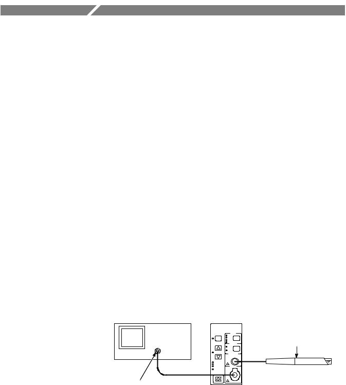
System Configuration
A complete current measurement system consists of a current probe amplifier, a compatible current probe, and an appropriate oscilloscope. Refer to Figure 1-1.
Test oscilloscope |
Amplifier |
Current probe
Input
Output
50 Ω oscilloscope input - use the TEKPROBE Interface Cable or use a 50 Ω cable. (Add 50 Ω termination here if oscilloscope has only high-impedance input.)
Figure 1- 1: Typical TCPA300/400 current measurement system
TCPA300/400 Amplifiers and TCP300/400 Series Current Probes Instruction Manual |
1- 1 |

Getting Started
TCPA300 and TCPA400 The amplifier amplifies the current sensed by the probe and converts the current Current Probe Amplifiers to a proportional voltage that is displayed on an oscilloscope or other similar
measuring device.
Current Probes The following Tektronix current probes are compatible with the TCPA300 Amplifier:
HTCP312 (30 amps, 100 MHz)
HTCP305 (50 amps, 50 MHz)
HTCP303 (150 amps, 15 MHz)
The following Tektronix current probes are compatible with the TCPA400
Amplifier:
HTCP404XL (750 amps*, 2 MHz)
*500 amps continuous, 750 amps DC derated with duty cycle
You can also use the CT-4 High-Current Transformer with the TCP305 and TCP312 current probes to extend the AC current measurement range to 20,000 peak amps.
Oscilloscope An oscilloscope displays the output from the current measuring system. A 50 Ω cable is included to connect the amplifier to the oscilloscope input channel. A TEKPROBE-to-TEKPROBE interface cable is also included for connecting to TEKPROBE level II oscilloscopes.
If the oscilloscope does not have an input that can be set to 50 Ω impedance, you need a feedthrough 50 Ω termination. This termination is included as a standard accessory with your TCPA300 and TCPA400 Current Probe Amplifiers.
1- 2 |
TCPA300/400 Amplifiers and TCP300/400 Series Current Probes Instruction Manual |

Getting Started
Options
Table 1-1 lists options that are available for the TCPA300 and TCPA400 amplifiers.
Table 1- 1: Amplifier options
Option |
Description |
|
|
A1 |
Universal Euro power cord |
|
|
A2 |
United Kingdom power cord |
|
|
A3 |
Australia power cord |
|
|
A5 |
Switzerland power cord |
|
|
A6 |
Japan power cord |
|
|
AC |
China power cord |
|
|
A99 |
No power cord |
|
|
L5 |
Japanese Instruction Manual |
|
|
Table 1-2 lists the Tektronix service options you can order for your amplifiers and probes. Designed to support tracking of calibration to requirements of ISO9000 and to provide for extended repair coverage, these options help fix your long-term maintenance costs and eliminate unplanned expenditures. Tektronix Service Options are available at the time you order your instrument. Contact your local Tektronix Sales Office for more information.
Table 1- 2: Service options
Option |
Description |
|
|
D1 |
Provides the initial Test Data Report from the factory on delivery. |
|
|
C3 |
Provides factory calibration certification on delivery, plus two more years of |
|
calibration coverage. Throughout the coverage period, the instrument will be |
|
calibrated according to its Recommended Calibration Interval. |
|
|
D3 |
Provides test data on delivery plus a Test Data Report for every calibration |
|
performed during three years of coverage (requires Option C3). |
|
|
R3 |
Extends product repair warranty to a total of three years. |
|
|
C5 |
Provides factory calibration certification on delivery, plus four more years of |
|
calibration coverage. Throughout the coverage period, the instrument will be |
|
calibrated according to its Recommended Calibration Interval. |
|
|
D5 |
Provides test data on delivery plus a Test Data Report for every calibration |
|
performed during five years of coverage (requires Option C5). |
|
|
R5 |
Extends product repair warranty to a total of five years. |
|
|
TCPA300/400 Amplifiers and TCP300/400 Series Current Probes Instruction Manual |
1- 3 |

Getting Started
Standard Accessories
The following accessories are shipped with the amplifiers and probes. Refer to the Replaceable Parts List beginning on page 8-1 for Tektronix part numbers to use in ordering accessories.
Amplifiers The following accessories are shipped with the TCPA300 and TCPA400 amplifiers.
HPower Cord (customer-chosen option)
HBNC Cable
HTermination, 50 Ω, 2W
HTEKPROBE Interconnect Cable
HInstruction Manual (English or Japanese; customer-chosen language option)
HCertificate of Traceable Calibration
Probes When you order a current probe, you will receive these accessories:
HProbe cover
HProbe ground lead, 6 inch length (TCP305 and TCP312 only)
HInstruction Sheet
HCertificate of Traceable Calibration
1- 4 |
TCPA300/400 Amplifiers and TCP300/400 Series Current Probes Instruction Manual |

Getting Started
Optional Accessories
You can order the following optional accessories for the amplifiers and probes. Refer to the Replaceable Parts List beginning on page 8-1 for Tektronix part numbers to use in ordering accessories.
HOne-turn 50 Ω current loop. The current loop is used in the performance verification procedure for checking the performance of the TCPA300 Amplifier and the compatible probes.
HCT-4 High-Current Transformer. If you need to measure high-amplitude AC currents, consider using the CT-4 with the TCP303 and TCP312 probes. The CT-4 provides step-down ratios of 20:1 or 1000:1. For more information about the CT-4, consult your Tektronix sales representative.
HTCPA Calibration Adapter. Use the TCPA Calibration Adapter to verify the amplifier(s) performance independent of the current probes.
HTravel Case. The travel case includes room to store one amplifier and two current probes, along with related cables and adapters.
HDeskew Fixture. This fixture converts the PROBE COMPENSATION output or TRIGGER OUTPUT of the TDS5000 or TDS7000 into a set of test point connections that allow you a convenient way to compensate for timing differences between voltage and current probes.
TCPA300/400 Amplifiers and TCP300/400 Series Current Probes Instruction Manual |
1- 5 |

Getting Started
Probe Covers
The TCP300/400 Series Current Probes come with a probe cover that stores the probe when not in use. Use the probe cover to hold your probe in a convenient place at your bench or workstation when you are not using it. You can attach the probe cover to the side of the bench to keep the probe off of your work surface. See Figure 1-2.
TCP305/312
TCP303/TCP404XL
Figure 1- 2: Using the probe covers
1- 6 |
TCPA300/400 Amplifiers and TCP300/400 Series Current Probes Instruction Manual |
Getting Started
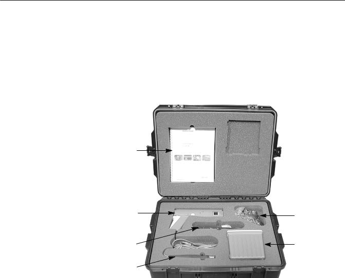
Travel Case
The travel case is a recommended accessory for the TCPA300/400 Amplifiers. The travel case includes room to store one amplifier and two TCP300/400 Series Current Probes, one of each size. (For example, you can store a TCP305 and a TCP303 probe.) A compartment is included to store associated cables and terminations. See Figure 1-3 for the proper location of the equipment.
Instruction
manual
Large current |
Cables & |
|
probe |
||
terminations |
||
|
||
Probe holders |
Amplifier |
Small current probe
Figure 1- 3: Equipment locations in the travel case
TCPA300/400 Amplifiers and TCP300/400 Series Current Probes Instruction Manual |
1- 7 |

Getting Started
Connecting the Amplifier to an Oscilloscope
You will need an oscilloscope to display the TCPA300 and TCPA400 measurement output. To use the full dynamic range of the probe/amplifier combination, the oscilloscope must be capable of displaying a vertical scale factor of 1 mV/div to 1V/div.
If you are using a TEKPROBE II-compatible oscilloscope, use the TEKPROBE- to-TEKPROBE interface cable. Otherwise, use the supplied 50 Ω BNC cable to connect the amplifier OUTPUT connector to your oscilloscope (see Figure 1-1 on page 1-1).
The input impedance of the oscilloscope channel must be 50 Ω, or you will encounter slowed pulse response, increased aberrations, or incorrect DC measurement amplitudes. If your oscilloscope provides only 1 MΩ inputs, you need to attach a 50 Ω feed-through termination between the oscilloscope input and the BNC cable. Do not install this termination at the amplifier end of the BNC cable.
To utilize the full bandwidth capability of the TCPA300 and TCPA400 and attached current probe, the oscilloscope bandwidth must be approximately five times that of the current probe. For example, when using a TCP312 Current Probe, the oscilloscope bandwidth must be at least 500 MHz. When using a TCP305 Current Probe, the oscilloscope bandwidth must be at least 250 MHz.
After you have connected the amplifier to the oscilloscope, allow the equipment to warm up to a stable temperature; usually 20 minutes is required.
Power on the Amplifier
Connect the power cord to the power input connector on the rear of the amplifier, and then connect the power cord to your local mains supply (100 VAC to 240 VAC, 50 Hz to 400 Hz). To allow for proper ventilation, place the rear panel of the amplifier at least 2 inches away from any obstructions. Set the amplifier on the bottom rubber feet, and keep papers and other items away from the bottom of the amplifier which could restrict airflow and cause overheating.
Power on the amplifier by pressing the ON/STANDBY button at the lower-left corner of the front panel. The amplifier goes through a self-test and cycles the front-panel LEDs.
NOTE. The amplifier stores the power state it is in when the power cord is unplugged. If you do not put the amplifier into STANDBY mode before unplugging it, the amplifier will power on immediately when you plug it in again.
When you connect a probe to the amplifier, the amplifier uses detection circuitry to indicate probe conditions such as noncompatible probe type and probe open.
1- 8 |
TCPA300/400 Amplifiers and TCP300/400 Series Current Probes Instruction Manual |
 Loading...