


 Loading...
Instruction Manual
P6015A
1000X High Voltage Probe
070-8223-05
Warning
The servicing instructions are for use by qualified personnel only. To avoid personal injury, do not perform any servicing unless you are qualified to do so. Refer to all safety summaries prior to performing service.
www.tektronix.com
Copyright © Tektronix. All rights reserved. Licensed software products are owned by Tektronix or its subsidiaries or suppliers, and are protected by national copyright laws and international treaty provisions.
Tektronix products are covered by U.S. and foreign patents, issued and pending. Information in this publication supercedes that in all previously published material. Specifications and price change privileges reserved.
TEKTRONIX and TEK are registered trademarks of Tektronix, Inc.
Contacting Tektronix
Tektronix, Inc.
14200 SW Karl Braun Drive
P.O. Box 500
Beaverton, OR 97077
USA
For product information, sales, service, and technical support:
HIn North America, call 1-800-833-9200.
HWorldwide, visit www.tektronix.com to find contacts in your area.
Warranty 2
Tektronix warrants that this product will be free from defects in materials and workmanship for a period of one (1) year from the date of shipment. If any such product proves defective during this warranty period, Tektronix, at its option, either will repair the defective product without charge for parts and labor, or will provide a replacement in exchange for the defective product. Parts, modules and replacement products used by Tektronix for warranty work may be new or reconditioned to like new performance. All replaced parts, modules and products become the property of Tektronix.
In order to obtain service under this warranty, Customer must notify Tektronix of the defect before the expiration of the warranty period and make suitable arrangements for the performance of service. Customer shall be responsible for packaging and shipping the defective product to the service center designated by Tektronix, with shipping charges prepaid. Tektronix shall pay for the return of the product to Customer if the shipment is to a location within the country in which the Tektronix service center is located. Customer shall be responsible for paying all shipping charges, duties, taxes, and any other charges for products returned to any other locations.
This warranty shall not apply to any defect, failure or damage caused by improper use or improper or inadequate maintenance and care. Tektronix shall not be obligated to furnish service under this warranty a) to repair damage resulting from attempts by personnel other than Tektronix representatives to install, repair or service the product; b) to repair damage resulting from improper use or connection to incompatible equipment; c) to repair any damage or malfunction caused by the use of non-Tektronix supplies; or d) to service a product that has been modified or integrated with other products when the effect of such modification or integration increases the time or difficulty of servicing the product.
THIS WARRANTY IS GIVEN BY TEKTRONIX WITH RESPECT TO THE PRODUCT IN LIEU OF ANY OTHER WARRANTIES, EXPRESS OR IMPLIED. TEKTRONIX AND ITS VENDORS DISCLAIM ANY IMPLIED WARRANTIES OF MERCHANTABILITY OR FITNESS FOR A PARTICULAR PURPOSE. TEKTRONIX’ RESPONSIBILITY TO REPAIR OR REPLACE DEFECTIVE PRODUCTS IS THE SOLE AND EXCLUSIVE REMEDY PROVIDED TO THE CUSTOMER FOR BREACH OF THIS WARRANTY. TEKTRONIX AND ITS VENDORS WILL NOT BE LIABLE FOR ANY INDIRECT, SPECIAL, INCIDENTAL, OR CONSEQUENTIAL DAMAGES IRRESPECTIVE OF WHETHER TEKTRONIX OR THE VENDOR HAS ADVANCE NOTICE OF THE POSSIBILITY OF SUCH DAMAGES.

Table of Contents
General Safety Summary . . . . . . . . . . . . . . . . . . . . . . . . . . . . |
v |
Service Safety Summary . . . . . . . . . . . . . . . . . . . . . . . . . . . . . |
vii |
Environmental Considerations . . . . . . . . . . . . . . . . . . . . . . . . |
viii |
User Information
Overview . . . . . . . . . . . . . . . . . . . . . . . . . . . . . . . . . . . . . . . . . . 1-1
Readout Option . . . . . . . . . . . . . . . . . . . . . . . . . . . . . . . . . . . . . 1-3
Standard Accessories . . . . . . . . . . . . . . . . . . . . . . . . . . . . . . . . . 1-4
Options . . . . . . . . . . . . . . . . . . . . . . . . . . . . . . . . . . . . . . . . . . . . 1-4
Setup . . . . . . . . . . . . . . . . . . . . . . . . . . . . . . . . . . . . . . . . . . . . . |
1-5 |
In Detail . . . . . . . . . . . . . . . . . . . . . . . . . . . . . . . . . . . . . . . . . . 1-7
General Guidelines . . . . . . . . . . . . . . . . . . . . . . . . . . . . . . . . . . 1-7 Maximum Input Voltage . . . . . . . . . . . . . . . . . . . . . . . . . . . . . . 1-10 Probe Grounding . . . . . . . . . . . . . . . . . . . . . . . . . . . . . . . . . . . . 1-13 Probe Compensation . . . . . . . . . . . . . . . . . . . . . . . . . . . . . . . . . 1-15 Caring for the Probe . . . . . . . . . . . . . . . . . . . . . . . . . . . . . . . . . 1-20 Other Considerations . . . . . . . . . . . . . . . . . . . . . . . . . . . . . . . . . 1-21 Problems Encountered Using the Probe . . . . . . . . . . . . . . . . . . 1-21
Specifications . . . . . . . . . . . . . . . . . . . . . . . . . . . . . . . . . . . . . . 1-23
Warranted Characteristics . . . . . . . . . . . . . . . . . . . . . . . . . . . . . 1-23
Typical and Nominal Characteristics . . . . . . . . . . . . . . . . . . . . 1-27
P6015A Instruction Manual |
i |

Table of Contents
Service Information
Performance Verification . . . . . . . . . . . . . . . . . . . . . . . . . . . . |
2-1 |
Adjustments . . . . . . . . . . . . . . . . . . . . . . . . . . . . . . . . . . . . . . . 2-3
Test Equipment Required . . . . . . . . . . . . . . . . . . . . . . . . . . . . . 2-3
Preparation . . . . . . . . . . . . . . . . . . . . . . . . . . . . . . . . . . . . . . . . . 2-3
Long-Form Procedure . . . . . . . . . . . . . . . . . . . . . . . . . . . . . . . . 2-5
Maintenance . . . . . . . . . . . . . . . . . . . . . . . . . . . . . . . . . . . . . . . 2-11
Preventive Maintenance . . . . . . . . . . . . . . . . . . . . . . . . . . . . . . 2-11
Troubleshooting and Repair . . . . . . . . . . . . . . . . . . . . . . . . . . . 2-12
Mechanical Disassembly and Assembly . . . . . . . . . . . . . . . . . . 2-13
Replaceable Parts . . . . . . . . . . . . . . . . . . . . . . . . . . . . . . . . . . . 2-17
Parts Ordering Information . . . . . . . . . . . . . . . . . . . . . . . . . . . . 2-17
Using the Replaceable Parts List . . . . . . . . . . . . . . . . . . . . . . . . 2-18
Index
ii |
P6015A Instruction Manual |

Table of Contents
List of Figures
Figure 1-1: The P6015A High-Voltage Probe . . . . . . . . . . . . 1-2 Figure 1-2: Compensation Box with Readout Option . . . . . 1-3 Figure 1-3: Assembling the P6015A . . . . . . . . . . . . . . . . . . . 1-5
Figure 1-4: Maximum Input Voltage Derating
(DC + Peak AC) . . . . . . . . . . . . . . . . . . . . . . . . . . . . . . . . . 1-12 Figure 1-5: Peak Pulse Derating . . . . . . . . . . . . . . . . . . . . . . 1-13 Figure 1-6: Zones Affected by Compensation Adjustments 1-18 Figure 1-7: Humidity Derating Chart . . . . . . . . . . . . . . . . . . 1-26 Figure 1-8: Typical Input Impedance and Phase . . . . . . . . . 1-26
Figure 2-1: Access to Long-Form Adjustments . . . . . . . . . . 2-5 Figure 2-2: Adjustment Locations . . . . . . . . . . . . . . . . . . . . . 2-7
Figure 2-3: Periods Affected by Compensation
Adjustments . . . . . . . . . . . . . . . . . . . . . . . . . . . . . . . . . . . . 2-8 Figure 2-4: Removal and Replacement of Probe Head . . . . 2-14 Figure 2-5: P6015A Exploded View . . . . . . . . . . . . . . . . . . . . 2-19
P6015A Instruction Manual |
iii |

Table of Contents
List of Tables
Table 1-1: Maximum Input Voltage1,2,3 . . . . . . . . . . . . . . . |
1-10 |
Table 1-2: Test Equipment Required for |
|
Short-Form Adjustment . . . . . . . . . . . . . . . . . . . . . . . . . . |
1-16 |
Table 1-3: Warranted Electrical Characteristics . . . . . . . . . |
1-24 |
Table 1-4: Warranted Environmental Characteristics . . . . |
1-25 |
Table 1-5: Typical Electrical Characteristics . . . . . . . . . . . . |
1-27 |
Table 1-6: Nominal Mechanical Characteristics . . . . . . . . . |
1-28 |
Table 2-1: Test Equipment Required for Long-Form |
|
Adjustment . . . . . . . . . . . . . . . . . . . . . . . . . . . . . . . . . . . . |
2-4 |
iv |
P6015A Instruction Manual |

General Safety Summary
Review the following safety precautions to avoid injury and prevent damage to this product or any products connected to it.
To avoid potential hazards, use this product only as specified.
Only qualified personnel should perform service procedures.
To Avoid Fire or Personal Injury
Connect and Disconnect Properly. Do not connect or disconnect probes or test leads while they are connected to a voltage source.
Connect and Disconnect Properly. Connect the probe output to the measurement instrument before connecting the probe to the circuit under test. Connect the probe reference lead to the circuit under test before connecting the probe input. Disconnect the probe input and the probe reference lead from the circuit under test before disconnecting the probe from the measurement instrument.
Ground the Product. This product is indirectly grounded through the grounding conductor of the mainframe power cord. To avoid electric shock, the grounding conductor must be connected to earth ground. Before making connections to the input or output terminals of the product, ensure that the product is properly grounded.
Observe All Terminal Ratings. To avoid fire or shock hazard, observe all ratings and markings on the product. Consult the product manual for further ratings information before making connections to the product.
The inputs are not rated for connection to mains or Category II, III, or IV circuits.
Connect the probe reference lead to earth ground only.
Do not apply a potential to any terminal, including the common terminal, that exceeds the maximum rating of that terminal.
Do Not Operate Without Covers. Do not operate this product with covers or panels removed.
Do Not Operate With Suspected Failures. If you suspect there is damage to this product, have it inspected by qualified service personnel.
] |
|
P6015A Instruction Manual |
v |
General Safety Summary
Avoid Exposed Circuitry. Do not touch exposed connections and components when power is present.
Do Not Operate in Wet/Damp Conditions.
Do Not Operate in an Explosive Atmosphere.
Keep Product Surfaces Clean and Dry.
Terms in this Manual
These terms may appear in this manual:
WARNING. Warning statements identify conditions or practices that could result in injury or loss of life.
CAUTION. Caution statements identify conditions or practices that could result in damage to this product or other property.
Symbols and Terms on the Product
These terms may appear on the product:
HDANGER indicates an injury hazard immediately accessible as you read the marking.
HWARNING indicates an injury hazard not immediately accessible as you read the marking.
HCAUTION indicates a hazard to property including the product. The following symbol(s) may appear on the product:
CAUTION |
WARNING |
Earth Terminal |
Refer to Manual |
High Voltage |
|
|
] |
vi |
P6015A Instruction Manual |
Service Safety Summary
Only qualified personnel should perform service procedures. Read this Service Safety Summary and the General Safety Summary before performing any service procedures.
Do Not Service Alone. Do not perform internal service or adjustments of this product unless another person capable of rendering first aid and resuscitation is present.
Use Care When Servicing with Power On. Dangerous voltages or currents may exist in this product. Disconnect power, remove battery (if applicable), and disconnect test leads before removing protective panels, soldering, or replacing components.
To avoid electric shock, do not touch exposed connections.
P6015A Instruction Manual |
vii |

Environmental Considerations
This section provides information about the environmental impact of the product.
Product End-of-Life Handling
Observe the following guidelines when recycling an instrument or component:
Equipment Recycling. Production of this equipment required the extraction and use of natural resources. The equipment may contain substances that could be harmful to the environment or human health if improperly handled at the product’s end of life. In order to avoid release of such substances into the environment and to reduce the use of natural resources, we encourage you to recycle this product in an appropriate system that will ensure that most of the materials are reused or recycled appropriately.
The symbol shown to the left indicates that this product complies with the European Union’s requirements according to Directive 2002/96/EC on waste electrical and electronic equipment (WEEE). For information about recycling options, check the Support/Service section of the Tektronix Web site (www.tektronix.com).
Restriction of Hazardous Substances
This product has been classified as Monitoring and Control equipment, and is outside the scope of the 2002/95/EC RoHS Directive. This product is known to contain lead, cadmium, mercury, and hexavalent chromium.
viii |
P6015A Instruction Manual |

User Information

Overview
The P6015A is a ground-referenced 100 MΩ, 3.0 pF high voltage probe with 1000X attenuation. It adds high-voltage measurement capability to oscilloscopes and other measurement devices having an input resistance of 1 MΩ and an input capacitance of 7 pF to 49 pF.
WARNING. Due to the inherent hazards associated with taking high-voltage measurements, this product is intended for use by qualified personnel who have had the training to take these types of measurements.
Read and follow the precautions specified in this manual.
The P6015A consists of two major assemblies: the probe body and the compensation box (see Figure 1-1).
HThe probe body houses the probe tip, head, and ground lead. The probe body is made of high-impact thermoplastic that provides mechanical protection for the probe’s internal components and electrical protection for the user.
HThe compensation box connects a ground-referenced oscilloscope or other grounded measuring device and has a cable that attaches to the probe body. The compensation box contains an adjustment network to optimize frequency response up to 75 MHz.
WARNING. To avoid shock, keep hands and fingers behind the guard ring on the probe when the probe is connected to voltages.
P6015A Instruction Manual |
1- 1 |

Overview
Guard Ring
Figure 1- 1: The P6015A High-Voltage Probe
1- 2 |
P6015A Instruction Manual |
Overview
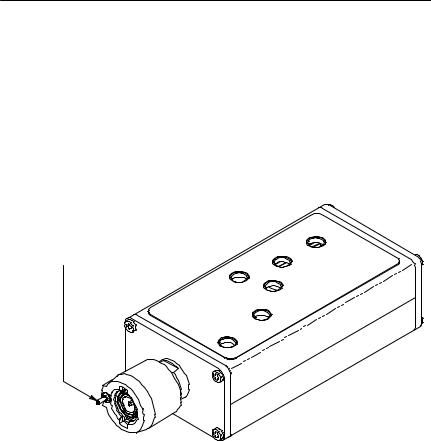
Readout Option
P6015A compensation boxes that feature the readout option have a pin protruding from the BNC connector (Figure 1-2). Some models of Tektronix oscilloscopes (11000 Series and Digital Storage Oscilloscopes) read the code presented by this pin and automatically scale the P6015A measurements by a factor of 1000 to compensate for attenuation.
1000X Readout Pin
Figure 1- 2: Compensation Box with Readout Option
P6015A Instruction Manual |
1- 3 |

Overview
Standard Accessories
The P6015A comes with the following accessories:
Hground lead and plug-on clip
Hhook-shaped probe tip
Hbanana-plug probe tip
Hcarrying case
Hinstruction manual
Options
The standard P6015A has a 10-ft cable without 1000X readout. The following options are available:
HOption 1R: 10-ft cable and 1000X readout
HOption 25: 25-ft cable, no readout
HOption 2R: 25-ft cable and 1000X readout
1- 4 |
P6015A Instruction Manual |

Setup
This section tells you how to assemble the P6015A modules as you unpack them from the carrying case. Refer to Figure 1-3 while following these steps:
Handle
Ground Lead
Inner Body 
Outer Body
Figure 1- 3: Assembling the P6015A
P6015A Instruction Manual |
1- 5 |

Setup
1.Insert the end of the cable into the narrow end of the handle and feed the BNC out the other side.
2.Connect the cable to the BNC on the probe head.
3.Screw the handle into the outer body.
4.Plug the crocodile ground clip onto the ground lead if it is not already attached.
5.Read In Detail, beginning on page 1-7, before attempting to make probe measurements.
1- 6 |
P6015A Instruction Manual |
In Detail
Before you make any oscilloscope measurement, observe all safety precautions described in the user and service manuals for the equipment you are working on. Some general rules about servicing electrical equipment are worth repeating here.
HObserve the safety instruction symbols for the equipment you are working on.
HConsult the service manual for the equipment you are working on.
HDon’t operate or service an electrical device in an explosive atmosphere.
HAvoid personal injury by never touching exposed connections or components in the circuit-under-test when the power is on.
General Guidelines
To make high-voltage measurements with the P6015A probe, first connect the BNC connector of the probe compensation box to the measurement device (oscilloscope, digital voltmeter, etc.). Next, connect the ground clip of the probe to a ground point of the circuit under test. After you have made these connections, you are ready to connect the probe tip to a high-voltage point.
Handheld Operation
The P6015A probe is designed for handheld use when used with the straight or hook shaped probe tips. When using the straight tip, the probe should be held by the plastic handle, behind the probe guard ring, and the tip should be held against the high voltage test point. The hook shaped tip can be used to hang the probe from a bus bar, wire loop, or other test point.
P6015A Instruction Manual |
1- 7 |

In Detail
WARNING. When measuring high voltages, avoid contact with or close proximity to any electrically conductive surface with your body. Keep hands and fingers behind the guard ring on the probe.
WARNING. Make sure that the circuit is deenergized, and that any stored energy is completely discharged before probe installation or removal. Failure to discharge the circuit may cause serous or fatal shock.
CAUTION. When mounting the probe into test fixtures, the duration ratings in Table 1-1 on page 1-10 must be followed. Only clamp onto the metal shield section of the probe when mounting the probe. Intense electric fields are present when the probe is connected to a high voltage source. Attaching a conductive or dielectric mount beyond the metal shield may result in poor response characteristics or probe damage.
Readout
If your P6015A has the readout option and is being used with an instrument having readout capability, the display automatically corrects for the probe attenuation factor. (Refer to Overview on page 1-1 for information about the P6015A readout option.)
If your instrument does not recognize the readout correction, multiply your voltage measurements by 1000.
NOTE. Some oscilloscopes may misinterpret the 1000X attenuation code. Contact your local Tektronix representative if you have questions.
1- 8 |
P6015A Instruction Manual |

In Detail
Probe Placement
CAUTION. Probe placement can be critical in some applications.
To minimize Device-Under-Test circuit loading, the P6015A input resistance is very large and input capacitance is very small. Small changes in capacitance near the input resistor will affect the accuracy of the measurement. These changes can result from placing the probe tip near conductive surfaces. Changes in the input capacitance will change the probe compensation, causing the leading edge of pulses to overshoot or undershoot the true pulse amplitude. The time constant will not be visible on shorter pulses where the entire top of the measured waveform will appear to be the wrong amplitude. Surfaces connected to the input signal will peak the response, resulting in overshoot, while those that are static or grounded will dampen the response, resulting in an undershoot.
To minimize the chance of changing the probe compensation, do not allow the conductor, to which the probe is attached, to pass along the side of the probe body. Keep the probe perpendicular to the attached conductor or at the end of a dedicated test lead. If the test configuration does not allow this, minimize the error by readjusting the probe compensation by connecting the probe to the calibration generator that closely duplicates the physical configuration used in the actual measurement.
P6015A Instruction Manual |
1- 9 |
Loading...