


Tektronix MSO2012, MSO2014, MSO2024, DPO2012, DPO2014 User Manual
...DPO2000 and MSO2000 Series
Oscilloscopes
User Manual
*P071231902*
071-2319-02

DPO2000 and MSO2000 Series
Oscilloscopes
User Manual
www.tektronix.com
071-2319-02

Copyright © Tektronix. All rights reserved. Licensed software products are owned by Tektronix or its subsidiaries or suppliers, and are protected by national copyright laws and international treaty provisions.
Tektronix products are covered by U.S. and foreign patents, issued and pending. Information in this publication supersedes that in all previously published material. Specifications and price change privileges reserved.
TEKTRONIX and TEK are registered trademarks of Tektronix, Inc.
e*Scope, FilterVu, OpenChoice, TekSecure, and TekVPI and Wave Inspector are registered trademarks of Tektronix, Inc.
PictBridge is a registered trademark of the Standard of Camera & Imaging Products Association CIPA DC-001-2003 Digital Photo Solutions for Imaging Devices.
Contacting Tektronix
Tektronix, Inc.
14200 SW Karl Braun Drive
P.O. Box 500
Beaverton, OR 97077
USA
For product information, sales, service, and technical support:
In North America, call 1-800-833-9200.
Worldwide, visit www.tektronix.com to find contacts in your area.
MSO2000 and DPO2000 Series Oscilloscopes
Warranty
Tektronix warrants that the product will be free from defects in materials and workmanship for a period of three (3) years from the date of original purchase from an authorized Tektronix distributor. If the product proves defective during this warranty period, Tektronix, at its option, either will repair the defective product without charge for parts and labor, or will provide a replacement in exchange for the defective product. Batteries are excluded from this warranty. Parts, modules and replacement products used by Tektronix for warranty work may be new or reconditioned to like new performance. All replaced parts, modules and products become the property of Tektronix.
In order to obtain service under this warranty, Customer must notify Tektronix of the defect before the expiration of the warranty period and make suitable arrangements for the performance of service. Customer shall be responsible for packaging and shipping the defective product to the service center designated by Tektronix, shipping charges prepaid, and with a copy of customer proof of purchase. Tektronix shall pay for the return of the product to Customer if the shipment is to a location within the country in which the Tektronix service center is located. Customer shall be responsible for paying all shipping charges, duties, taxes, and any other charges for products returned to any other locations.
This warranty shall not apply to any defect, failure or damage caused by improper use or improper or inadequate maintenance and care. Tektronix shall not be obligated to furnish service under this warranty a) to repair damage resulting from attempts by personnel other than Tektronix representatives to install, repair or service the product; b) to repair damage resulting from improper use or connection to incompatible equipment; c) to repair any damage or malfunction caused by the use of non-Tektronix supplies; or
d) to service a product that has been modified or integrated with other products when the effect of such modification or integration increases the time or difficulty of servicing the product.
THIS WARRANTY IS GIVEN BY TEKTRONIX WITH RESPECT TO THE PRODUCT IN LIEU OF ANY OTHER WARRANTIES, EXPRESS OR IMPLIED. TEKTRONIX AND ITS VENDORS DISCLAIM ANY IMPLIED WARRANTIES OF MERCHANTABILITY OR FITNESS FOR A PARTICULAR PURPOSE. TEKTRONIX’ RESPONSIBILITY TO REPAIR OR REPLACE DEFECTIVE PRODUCTS IS THE SOLE AND EXCLUSIVE REMEDY PROVIDED TO THE CUSTOMER FOR BREACH OF THIS WARRANTY. TEKTRONIX AND ITS VENDORS WILL NOT BE LIABLE FOR ANY INDIRECT, SPECIAL, INCIDENTAL, OR CONSEQUENTIAL DAMAGES IRRESPECTIVE OF WHETHER TEKTRONIX OR THE VENDOR HAS ADVANCE NOTICE OF THE POSSIBILITY OF SUCH DAMAGES.
[W16 – 15AUG04]
P2221 Probe
Warranty
Tektronix warrants that this product will be free from defects in materials and workmanship for a period of one (1) year from the date of shipment. If any such product proves defective during this warranty period, Tektronix, at its option, either will repair the defective product without charge for parts and labor, or will provide a replacement in exchange for the defective product. Parts, modules and replacement products used by Tektronix for warranty work may be new or reconditioned to like new performance. All replaced
parts, modules and products become the property of Tektronix.
In order to obtain service under this warranty, Customer must notify Tektronix of the defect before the expiration of the warranty period and make suitable arrangements for the performance of service. Customer shall be responsible for packaging and shipping the defective product to the service center designated by Tektronix, with shipping charges prepaid. Tektronix shall pay for the return of the product to Customer if the shipment is to a location within the country in which the Tektronix service center is located. Customer shall be responsible for paying all shipping charges, duties, taxes, and any other charges for products returned to any other locations.
This warranty shall not apply to any defect, failure or damage caused by improper use or improper or inadequate maintenance and care. Tektronix shall not be obligated to furnish service under this warranty a) to repair damage resulting from attempts by personnel other than Tektronix representatives to install, repair or service the product; b) to repair damage resulting from improper use or connection to incompatible equipment; c) to repair any damage or malfunction caused by the use of non-Tektronix supplies; or
d) to service a product that has been modified or integrated with other products when the effect of such modification or integration increases the time or difficulty of servicing the product.
THIS WARRANTY IS GIVEN BY TEKTRONIX WITH RESPECT TO THE PRODUCT IN LIEU OF ANY OTHER WARRANTIES, EXPRESS OR IMPLIED. TEKTRONIX AND ITS VENDORS DISCLAIM ANY IMPLIED WARRANTIES OF MERCHANTABILITY OR FITNESS FOR A PARTICULAR PURPOSE. TEKTRONIX’ RESPONSIBILITY TO REPAIR OR REPLACE DEFECTIVE PRODUCTS IS THE SOLE AND EXCLUSIVE REMEDY PROVIDED TO THE CUSTOMER FOR BREACH OF THIS WARRANTY. TEKTRONIX AND ITS VENDORS WILL NOT BE LIABLE FOR ANY INDIRECT, SPECIAL, INCIDENTAL, OR CONSEQUENTIAL DAMAGES IRRESPECTIVE OF WHETHER TEKTRONIX OR THE VENDOR HAS ADVANCE NOTICE OF THE POSSIBILITY OF SUCH DAMAGES.
[W2 – 15AUG04]
P6316 Probe
Warranty
Tektronix warrants that the product will be free from defects in materials and workmanship for a period of one (1) year from the date of original purchase from an authorized Tektronix distributor. If the product proves defective during this warranty period, Tektronix, at its option, either will repair the defective product without charge for parts and labor, or will provide a replacement in exchange for the defective product. Batteries are excluded from this warranty. Parts, modules and replacement products used by Tektronix for warranty work may be new or reconditioned to like new performance. All replaced parts, modules and products become the property of Tektronix.
In order to obtain service under this warranty, Customer must notify Tektronix of the defect before the expiration of the warranty period and make suitable arrangements for the performance of service. Customer shall be responsible for packaging and shipping the defective product to the service center designated by Tektronix, shipping charges prepaid, and with a copy of customer proof of purchase. Tektronix shall pay for the return of the product to Customer if the shipment is to a location within the country in which the Tektronix service center is located. Customer shall be responsible for paying all shipping charges, duties, taxes, and any other charges for products returned to any other locations.
This warranty shall not apply to any defect, failure or damage caused by improper use or improper or inadequate maintenance and care. Tektronix shall not be obligated to furnish service under this warranty a) to repair damage resulting from attempts by personnel other than Tektronix representatives to install, repair or service the product; b) to repair damage resulting from improper use or connection to incompatible equipment; c) to repair any damage or malfunction caused by the use of non-Tektronix supplies; or
d) to service a product that has been modified or integrated with other products when the effect of such modification or integration increases the time or difficulty of servicing the product.
THIS WARRANTY IS GIVEN BY TEKTRONIX WITH RESPECT TO THE PRODUCT IN LIEU OF ANY OTHER WARRANTIES, EXPRESS OR IMPLIED. TEKTRONIX AND ITS VENDORS DISCLAIM ANY IMPLIED WARRANTIES OF MERCHANTABILITY OR FITNESS FOR A PARTICULAR PURPOSE. TEKTRONIX’ RESPONSIBILITY TO REPAIR OR REPLACE DEFECTIVE PRODUCTS IS THE SOLE AND EXCLUSIVE REMEDY PROVIDED TO THE CUSTOMER FOR BREACH OF THIS WARRANTY. TEKTRONIX AND ITS VENDORS WILL NOT BE LIABLE FOR ANY INDIRECT, SPECIAL, INCIDENTAL, OR CONSEQUENTIAL DAMAGES IRRESPECTIVE OF WHETHER TEKTRONIX OR THE VENDOR HAS ADVANCE NOTICE OF THE POSSIBILITY OF SUCH DAMAGES.
[W15 – 15AUG04]

|
Table of Contents |
Table of Contents |
|
General Safety Summary . .. . .. . .. . . . . . . . .. . .. . .. . .. . .. . . . . . . . .. . .. . .. . .. . .. . .. . . . . .. . .. . .. . .. . .. . .. . . . . .. . .. . .. . .. . .. . |
.. . .. . . . . .. . .. . iii |
Compliance Information .. . .. . .. . .. . .. . . . . .. . .. . .. . .. . .. . .. . . . . .. . .. . .. . .. . .. . .. . . . . . . . .. . .. . .. . .. . .. . . . . . . . .. . .. . .. . .. . |
.. . .. . . . . .. . .. . v |
EMC Compliance. . . . . .. . .. . .. . .. . .. . .. . . . . .. . .. . .. . .. . .. . .. . . . . . . . .. . .. . .. . .. . .. . . . . . . . .. . .. . .. . .. . .. . .. . . . . . . . .. . . |
. . .. . .. . .. . .. . v |
Safety Compliance .. . .. . .. . .. . .. . . . . . . . .. . .. . .. . .. . .. . .. . . . . .. . .. . .. . .. . .. . .. . . . . .. . .. . .. . .. . .. . .. . . . . . . . .. . .. . .. . . |
. . .. . .. . . . . . . vii |
Environmental Considerations.. . .. . .. . . . . .. . .. . .. . .. . .. . .. . . . . . . . .. . .. . .. . .. . .. . . . . . . . .. . .. . .. . .. . .. . .. . . . . . . . .. . . |
. . .. . .. . .. . .. . ix |
Preface .. . .. . . . . .. . .. . .. . .. . .. . .. . . . . . . . .. . .. . .. . .. . .. . . . . . . . .. . .. . .. . .. . .. . .. . . . . .. . .. . .. . .. . .. . .. . . . . .. . .. . .. . .. . .. . .. . . |
. . . . ... . .. . . . . x |
Key Features . . . . . . .. . .. . .. . .. . .. . . . . . . . .. . .. . .. . .. . .. . .. . . . . .. . .. . .. . .. . .. . .. . . . . .. . .. . .. . .. . .. . .. . . . . . . . .. . .. . .. . . |
. . .. . .. . . . . . .. x |
Conventions Used in This Manual. . .. . .. . . . . .. . .. . .. . .. . .. . .. . . . . . . . .. . .. . .. . .. . .. . . . . . . . .. . .. . .. . .. . .. . .. . . . . . . . . |
. . .. . .. . .. . .. . xi |
Installation.. . .. . .. . .. . . . . .. . .. . .. . .. . .. . .. . . . . . . . .. . .. . .. . .. . .. . . . . . . . .. . .. . .. . .. . .. . .. . . . . .. . .. . .. . .. . .. . .. . . . . .. . .. . .. . . |
. . .. . .. . . . . . . . 1 |
Before Installation . .. . .. . .. . .. . .. . . . . . . . .. . .. . .. . .. . .. . .. . . . . .. . .. . .. . .. . .. . .. . . . . .. . .. . .. . .. . .. . .. . . . . . . . .. . .. . .. . . |
. . .. . .. . . . ... . 1 |
Operating Considerations. . .. . .. . . . . . . . .. . .. . .. . .. . .. . .. . . . . .. . .. . .. . .. . .. . .. . . . . .. . .. . .. . .. . .. . .. . . . . . . . .. . .. . .. . . |
. . .. . .. . . . . . . . 5 |
Connecting Probes. . . .. . .. . .. . .. . .. . .. . . . . .. . .. . .. . .. . .. . .. . . . . .. . .. . .. . .. . .. . .. . . . . . . . .. . .. . .. . .. . .. . . . . . . . . . . .. . . |
. . .. . .. . .. . . . . 8 |
Securing the Oscilloscope . .. . .. . .. . .. . .. . . . . . . . .. . .. . .. . .. . .. . .. . . . . .. . .. . .. . .. . .. . .. . . . . .. . .. . .. . .. . .. . .. . . . . . . . . |
. . .. . .. . .. . .. . 9 |
Powering On the Oscilloscope . . .. . .. . .. . .. . .. . . . . . . . .. . .. . .. . .. . .. . .. . . . . .. . .. . .. . .. . .. . .. . . . . .. . .. . .. . .. . .. . .. . . |
. . . . . .. . .. . .. 10 |
Powering Off the Oscilloscope. . . .. . .. . .. . .. . .. . .. . . . . . . . .. . .. . .. . .. . .. . . . . . . . .. . .. . .. . .. . .. . .. . . . . .. . .. . .. . .. . .. . . |
. . .. . . . . .. . .. 11 |
Functional Check. . .. . .. . .. . .. . .. . .. . . . . . . . .. . .. . .. . .. . .. . . . . . . . .. . .. . .. . .. . .. . .. . . . . .. . .. . .. . .. . .. . .. . . . . .. . .. . .. . . |
. . .. . .. . .. . . . 11 |
Compensating a Passive Voltage Probe . .. . . . . . . . .. . .. . .. . .. . .. . . . . . . . .. . .. . .. . .. . .. . .. . . . . .. . .. . .. . .. . .. . .. . . . . . |
. . .. . .. . .. . .. 12 |
Application Module Free Trial. .. . .. . .. . .. . .. . . . . .. . .. . .. . .. . .. . .. . . . . . . . .. . .. . .. . .. . .. . . . . . . . .. . .. . .. . .. . .. . .. . . . . . |
. . .. . .. . .. . .. 14 |
Installing an Application Module . .. . .. . .. . .. . .. . .. . . . . . . . .. . .. . .. . .. . .. . . . . . . . .. . .. . .. . .. . .. . .. . . . . .. . .. . .. . .. . .. . . |
. . . . . . . . .. . .. 14 |
Changing the User Interface Language . . .. . .. . .. . .. . .. . . . . . . . .. . .. . .. . .. . .. . .. . . . . .. . .. . .. . .. . .. . .. . . . . .. . .. . .. . . |
. . .. . .. . .. . . . 14 |
Changing the Date and Time . .. . .. . .. . .. . .. . . . . . . . .. . .. . .. . .. . .. . .. . . . . .. . .. . .. . .. . .. . .. . . . . .. . .. . .. . .. . .. . .. . .. . . |
. . .. . .. . .. . .. 15 |
Signal Path Compensation .. . .. . . . . . . . .. . .. . .. . .. . .. . .. . . . . .. . .. . .. . .. . .. . .. . . . . .. . .. . .. . .. . .. . .. . . . . . . . .. . .. . .. . . |
. . .. . .. . . . . . . 17 |
Upgrading Firmware . .. . . . . . . . .. . .. . .. . .. . .. . .. . . . . .. . .. . .. . .. . .. . .. . . . . .. . .. . .. . .. . .. . .. . . . . . . . .. . .. . .. . .. . .. . .. . . |
. . . . . .. . .. . .. 18 |
Connecting Your Oscilloscope to a Computer . .. . .. . .. . .. . . . . . . . .. . .. . .. . .. . .. . .. . . . . .. . .. . .. . .. . .. . .. . . . . . . . .. . . |
. . .. . .. . .. . .. 21 |
Connecting a USB Keyboard to Your Oscilloscope. . .. . .. . .. . .. . .. . . . . .. . .. . .. . .. . .. . .. . . . . .. . .. . .. . .. . .. . .. . .. . . |
. . .. . .. . .. . .. 25 |
Getting Acquainted with the Oscilloscope . . .. . .. . .. . . . . . . . .. . .. . .. . .. . .. . .. . . . . .. . .. . .. . .. . .. . .. . . . . .. . .. . .. . .. . .. . .. . . |
. . . . . .. . .. . .. 27 |
Front-Panel Menus and Controls . . . . . . .. . .. . .. . .. . .. . .. . . . . .. . .. . .. . .. . .. . .. . . . . .. . .. . .. . .. . .. . .. . . . . . . . .. . .. . .. . . |
. . .. . .. . . . . . . 27 |
Front-Panel Connectors .. . .. . .. . .. . .. . .. . . . . .. . .. . .. . .. . .. . .. . . . . .. . .. . .. . .. . .. . .. . . . . . . . .. . .. . .. . .. . .. . . . . . . . . . . . |
. . .. . .. . .. . .. 39 |
Side-Panel Connector.. . . . . . . . .. . .. . .. . .. . .. . .. . . . . .. . .. . .. . .. . .. . .. . . . . .. . .. . .. . .. . .. . .. . . . . . . . .. . .. . .. . .. . .. . .. . . |
. . . . . .. . .. . .. 39 |
Rear-Panel Connectors . .. . .. . .. . .. . . . . .. . .. . .. . .. . .. . .. . . . . .. . .. . .. . .. . .. . .. . . . . . . . .. . .. . .. . .. . .. . . . . . . . .. . .. . .. . . |
. . .. . .. . . . . . . 40 |
Acquire the Signal .. . .. . .. . . . . .. . .. . .. . .. . .. . .. . . . . . . . .. . .. . .. . .. . .. . . . . . . . .. . .. . .. . .. . .. . .. . . . . .. . .. . .. . .. . .. . .. . . . . . . . . |
. . .. . .. . .. . .. 41 |
Setting Up Analog Channels. . .. . .. . .. . .. . .. . . . . .. . .. . .. . .. . .. . .. . . . . .. . .. . .. . .. . .. . .. . . . . . . . .. . .. . .. . .. . .. . . . . . . . . |
. . .. . .. . .. . .. 41 |
Using the Default Setup. .. . . . . . . . .. . .. . .. . .. . .. . . . . . . . .. . .. . .. . .. . .. . .. . . . . .. . .. . .. . .. . .. . .. . . . . .. . .. . .. . .. . .. . .. . . |
. . . . . .. . .. . .. 44 |
Using Autoset . . . . . .. . .. . .. . .. . .. . .. . . . . . . . .. . .. . .. . .. . .. . . . . . . . .. . .. . .. . .. . .. . .. . . . . .. . .. . .. . .. . .. . .. . . . . .. . .. . .. . . |
. . .. . .. . .. . . . 45 |
Acquisition Concepts. .. . .. . .. . .. . . . . .. . .. . .. . .. . .. . .. . . . . .. . .. . .. . .. . .. . .. . . . . . . . .. . .. . .. . .. . .. . . . . . . . .. . .. . .. . .. . . |
. . .. . . . . . . . .. 46 |
How the Analog Acquisition Modes Work .. . .. . .. . .. . .. . . . . .. . .. . .. . .. . .. . .. . . . . . . . .. . .. . .. . .. . .. . . . . . . . .. . .. . .. . . |
. . .. . .. . . . . . . 48 |
Changing the Acquisition Mode, Record Length, and Delay Time. .. . .. . .. . . . . . . . .. . .. . .. . .. . .. . . . . . . . .. . .. . .. . . |
. . .. . .. . . . . . . 48 |
Using Roll Mode. . . .. . .. . .. . .. . .. . . . . . . . .. . .. . .. . .. . .. . .. . . . . .. . .. . .. . .. . .. . .. . . . . .. . .. . .. . .. . .. . .. . . . . . . . .. . .. . .. . . |
. . .. . .. . . . . . . 50 |
Setting Up a Serial or Parallel Bus . . . . . . . .. . .. . .. . .. . .. . . . . . . . .. . .. . .. . .. . .. . .. . . . . .. . .. . .. . .. . .. . .. . . . . .. . .. . .. . . |
. . .. . .. . .. . . . 51 |
Setting Up Digital Channels (MSO2000 Series Only) . . .. . .. . . . . . . . .. . .. . .. . .. . .. . .. . . . . .. . .. . .. . .. . .. . .. . . . . . . . . |
. . .. . .. . .. . .. 60 |
Reducing Unwanted Noise With FilterVu .. . . . . .. . .. . .. . .. . .. . .. . . . . . . . .. . .. . .. . .. . .. . . . . . . . .. . .. . .. . .. . .. . .. . . . . . |
. . .. . .. . .. . .. 61 |
Using FilterVu . . . . . .. . .. . .. . .. . .. . .. . . . . . . . .. . .. . .. . .. . .. . . . . . . . .. . .. . .. . .. . .. . .. . . . . .. . .. . .. . .. . .. . .. . . . . .. . .. . .. . . |
. . .. . .. . .. . .. 63 |
DPO2000 and MSO2000 Series Oscilloscopes User Manual |
i |

Table of Contents |
|
Trigger Setup . . .. . .. . .. . .. . .. . .. . . . . .. . .. . .. . .. . .. . .. . . . . . . . .. . .. . .. . .. . .. . .. . . . . . . . .. . .. . .. . .. . .. . . . . . . . .. . .. . .. . .. . .. . . . . . . . ... .. . .. |
65 |
Triggering Concepts. . . . . .. . .. . .. . .. . .. . . . . . . . .. . .. . .. . .. . .. . . . . . . . . . . .. . .. . .. . .. . .. . . . . . . . .. . .. . .. . .. . .. . .. . . . . .. . .. . .. . .. . .. . .. |
65 |
Choosing a Trigger Type. . . . . . .. . .. . .. . .. . .. . . . . . . . .. . .. . .. . .. . .. . .. . . . . . . . .. . .. . .. . .. . .. . .. . . . . .. . .. . .. . .. . .. . .. . . . . .. . .. . .. . .. |
68 |
Selecting Triggers . .. . .. . .. . . . . .. . .. . .. . .. . .. . .. . . . . . . . .. . .. . .. . .. . .. . .. . . . . . . . .. . .. . .. . .. . .. . . . . . . . .. . .. . .. . .. . .. . .. . . . . .. . .. . .. |
68 |
Triggering on Buses. . . . . .. . .. . .. . .. . .. . .. . . . . .. . .. . .. . .. . .. . .. . . . . . . . .. . .. . .. . .. . .. . .. . . . . . . . .. . .. . .. . .. . .. . . . . . . . .. . .. . .. . .. . .. |
70 |
Checking Trigger Settings . . . . . . . .. . .. . .. . .. . .. . .. . . . . .. . .. . .. . .. . .. . .. . .. . . . . .. . .. . .. . .. . .. . .. . . . . .. . .. . .. . .. . .. . .. . . . . . . . .. . .. |
74 |
Starting and Stopping an Acquisition. . .. . .. . .. . . . . .. . .. . .. . .. . .. . .. . .. . . . . .. . .. . .. . .. . .. . .. . . . . . . . .. . .. . .. . .. . .. . . . . . . . .. . .. . .. |
75 |
Display Waveform Data .. . .. . . . . . . . .. . .. . .. . .. . .. . . . . . . . .. . .. . .. . .. . .. . .. . . . . . . . .. . .. . .. . .. . .. . .. . . . . .. . .. . .. . .. . .. . .. . . . . .. . .. . .. . .. |
76 |
Adding and Removing a Waveform .. . .. . . . . .. . .. . .. . .. . .. . .. . . . . . . . .. . .. . .. . .. . .. . .. . . . . . . . .. . .. . .. . .. . .. . . . . . . . .. . .. . .. . .. . .. |
76 |
Setting the Display Style and Persistence . . . . . .. . .. . .. . .. . .. . .. . .. . . . . .. . .. . .. . .. . .. . .. . . . . .. . .. . .. . .. . .. . .. . . . . . . . .. . .. . .. . .. |
76 |
Setting Waveform Intensity . . . .. . .. . .. . .. . .. . . . . . . . .. . .. . .. . .. . .. . .. . . . . . . . .. . .. . .. . .. . .. . .. . . . . .. . .. . .. . .. . .. . .. . . . . .. . .. . .. . .. |
79 |
Scaling and Positioning a Waveform . . .. . .. . . . . .. . .. . .. . .. . .. . .. . .. . . . . .. . .. . .. . .. . .. . .. . . . . .. . .. . .. . .. . .. . .. . . . . . . . .. . .. . .. . .. |
80 |
Setting Input Parameters . . .. . . . . . . . .. . .. . .. . .. . .. . . . . . . . .. . .. . .. . .. . .. . .. . . . . . . . .. . .. . .. . .. . .. . .. . . . . .. . .. . .. . .. . .. . .. . . . . .. . .. |
81 |
Positioning and Labeling Bus Signals . .. . .. . . . . .. . .. . .. . .. . .. . .. . .. . . . . .. . .. . .. . .. . .. . .. . . . . .. . .. . .. . .. . .. . .. . . . . . . . .. . .. . .. . .. |
83 |
Positioning, Scaling, and Grouping Digital Channels.. . .. . .. . .. . . . . . . . .. . .. . .. . .. . .. . .. . . . . .. . .. . .. . .. . .. . .. . . . . .. . .. . .. . .. . .. |
83 |
Viewing Digital Channels . . .. . .. . . . . . . . .. . .. . .. . .. . .. . . . . . . . .. . .. . .. . .. . .. . .. . . . . . . . .. . .. . .. . .. . .. . . . . . . . .. . .. . .. . .. . .. . .. . . . . .. |
85 |
Annotating the Screen . . .. . . . . .. . .. . .. . .. . .. . .. . . . . . . . .. . .. . .. . .. . .. . .. . . . . . . . .. . .. . .. . .. . .. . . . . . . . .. . .. . .. . .. . .. . .. . . . . .. . .. . .. |
86 |
Analyze Waveform Data.. . . . . . . . .. . .. . .. . .. . .. . .. . . . . .. . .. . .. . .. . .. . .. . .. . . . . .. . .. . .. . .. . .. . .. . . . . .. . .. . .. . .. . .. . .. . . . . . . . .. . .. . .. ... |
87 |
Taking Automatic Measurements. . . . . . .. . .. . .. . .. . .. . . . . . . . .. . .. . .. . .. . .. . .. . . . . . . . .. . .. . .. . .. . .. . .. . . . . .. . .. . .. . .. . .. . .. . . . . .. |
87 |
Selecting Automatic Measurements.. . .. . .. . . . . .. . .. . .. . .. . .. . .. . .. . . . . .. . .. . .. . .. . .. . .. . . . . .. . .. . .. . .. . .. . .. . . . . . . . .. . .. . .. . .. |
88 |
Customizing an Automatic Measurement . . . .. . .. . .. . .. . .. . . . . . . . . . . .. . .. . .. . .. . .. . . . . . . . .. . .. . .. . .. . .. . .. . . . . .. . .. . .. . .. . .. . .. |
91 |
Taking Manual Measurements with Cursors .. . .. . .. . . . . . . . .. . .. . .. . .. . .. . .. . . . . . . . .. . .. . .. . .. . .. . . . . . . . .. . .. . .. . .. . .. . .. . . . . .. |
94 |
Using Math Waveforms . . . . .. . .. . .. . .. . .. . .. . . . . .. . .. . .. . .. . .. . .. . .. . . . . .. . .. . .. . .. . .. . .. . . . . .. . .. . .. . .. . .. . .. . . . . . . . .. . .. . .. . .. |
97 |
Using FFT .. . .. . . . . .. . .. . .. . .. . .. . .. . . . . .. . .. . .. . .. . .. . .. . . . . . . . .. . .. . .. . .. . .. . .. . . . . . . . .. . .. . .. . .. . .. . . . . . . . .. . .. . .. . .. . .. . .. . . . |
98 |
Using Reference Waveforms . .. . .. . .. . .. . .. . . . . . . . .. . .. . .. . .. . .. . .. . . . . . . . .. . .. . .. . .. . .. . .. . . . . .. . .. . .. . .. . .. . .. . . . . .. . .. . .. . |
101 |
Using Wave Inspector to Manage Long Record Length Waveforms. . .. . .. . .. . .. . .. . . . . . . . .. . .. . .. . .. . .. . .. . . . . .. . .. . .. . .. . |
103 |
Save and Recall Information . .. . .. . .. . .. . .. . .. . . . . .. . .. . .. . .. . .. . .. . . . . . . . .. . .. . .. . .. . .. . .. . . . . . . . .. . .. . .. . .. . .. . . . . . . . .. . .. . .. . .. . |
109 |
Saving a Screen Image . .. . .. . .. . .. . .. . .. . . . . .. . .. . .. . .. . .. . .. . . . . . . . .. . .. . .. . .. . .. . .. . . . . . . . .. . .. . .. . .. . .. . . . . . . . .. . .. . .. . .. . . |
111 |
Saving and Recalling Waveform Data. .. . .. . .. . .. . .. . .. . . . . .. . .. . .. . .. . .. . .. . .. . . . . .. . .. . .. . .. . .. . .. . . . . . . . .. . .. . .. . .. . .. . . . . |
112 |
Saving and Recalling Setups . .. . .. . .. . .. . .. . . . . .. . .. . .. . .. . .. . .. . .. . . . . .. . .. . .. . .. . .. . .. . . . . .. . .. . .. . .. . .. . .. . . . . . . . .. . .. . .. . |
114 |
Saving with One Button Push .. . .. . .. . .. . .. . .. . . . . . . . .. . .. . .. . .. . .. . .. . . . . . . . .. . .. . .. . .. . .. . . . . . . . .. . .. . .. . .. . .. . .. . . . . .. . .. . |
116 |
Saving Setup, Screen Image, and Waveform Files. . .. . . . . . . . .. . .. . .. . .. . . . . . . . .. . .. . .. . .. . . . . . . . .. . .. . .. . .. . . . . . . . .. . .. . .. . |
116 |
Printing a Hard Copy. .. . .. . .. . . . . . . . .. . .. . .. . .. . .. . .. . . . . .. . .. . .. . .. . .. . .. . .. . . . . .. . .. . .. . .. . .. . .. . . . . .. . .. . .. . .. . .. . .. . . . . . . . |
118 |
Erasing Oscilloscope Memory .. . .. . .. . .. . . . . . . . .. . .. . .. . .. . .. . . . . . . . . . . .. . .. . .. . .. . .. . . . . . . . .. . .. . .. . .. . .. . .. . . . . .. . .. . .. . .. . |
120 |
Using Application Modules .. . .. . .. . . . . .. . .. . .. . .. . .. . .. . . . . .. . .. . .. . .. . .. . .. . .. . . . . .. . .. . .. . .. . .. . .. . . . . .. . .. . .. . .. . .. . .. . . . . . . . .. . |
122 |
Appendix: Warranted Specifications, Safety Certifications, and Electromagnetic Compatibility . . .. . .. . .. . .. . .. . . . . . . . .. . .. . .. . |
123 |
Index |
|
ii |
DPO2000 and MSO2000 Series Oscilloscopes User Manual |
General Safety Summary
General Safety Summary
Review the following safety precautions to avoid injury and prevent damage to this product or any products connected to it.
To avoid potential hazards, use this product only as specified.
Only qualified personnel should perform service procedures.
To Avoid Fire or Personal Injury
Use Proper Power Cord. Use only the power cord specified for this product and certified for the country of use.
Connect and Disconnect Properly. Do not connect or disconnect probes or test leads while they are connected to a voltage source.
Connect and Disconnect Properly. De-energize the circuit under test before connecting or disconnecting the current probe.
Ground the Product. This product is grounded through the grounding conductor of the power cord. To avoid electric shock, the grounding conductor must be connected to earth ground. Before making connections to the input or output terminals of the product, ensure that the product is properly grounded.
Observe All Terminal Ratings. To avoid fire or shock hazard, observe all ratings and markings on the product. Consult the product manual for further ratings information before making connections to the product.
Connect the probe reference lead to earth ground only.
Do not apply a potential to any terminal, including the common terminal, that exceeds the maximum rating of that terminal.
Power Disconnect. The power cord disconnects the product from the power source. Do not block the power cord; it must remain accessible to the user at all times.
Do Not Operate Without Covers. Do not operate this product with covers or panels removed.
Do Not Operate With Suspected Failures. If you suspect that there is damage to this product, have it inspected by qualified service personnel.
Avoid Exposed Circuitry. Do not touch exposed connections and components when power is present.
Do Not Operate in Wet/Damp Conditions. Do Not Operate in an Explosive Atmosphere. Keep Product Surfaces Clean and Dry.
Provide Proper Ventilation. Refer to the manual’s installation instructions for details on installing the product so it has proper ventilation.
Terms in this Manual
These terms may appear in this manual:
WARNING. Warning statements identify conditions or practices that could result in injury or loss of life.
DPO2000 and MSO2000 Series Oscilloscopes User Manual |
iii |
General Safety Summary
CAUTION. Caution statements identify conditions or practices that could result in damage to this product or other property.
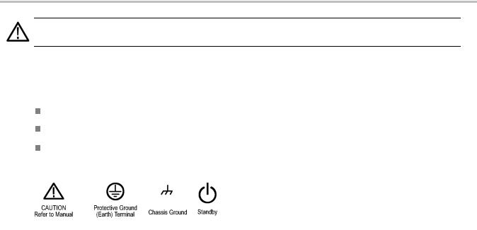
Symbols and Terms on the Product
These terms may appear on the product:
DANGER indicates an injury hazard immediately accessible as you read the marking.
WARNING indicates an injury hazard not immediately accessible as you read the marking.
CAUTION indicates a hazard to property including the product.
The following symbol(s) may appear on the product:
iv |
DPO2000 and MSO2000 Series Oscilloscopes User Manual |

Compliance Information
Compliance Information
This section lists the EMC (electromagnetic compliance), safety, and environmental standards with which the instrument complies.
EMC Compliance
EC Declaration of Conformity – EMC
Meets intent of Directive 2004/108/EC for Electromagnetic Compatibility. Compliance was demonstrated to the following specifications as listed in the Official Journal of the European Communities:
EN 61326-1:2006, EN 61326-2-1:2006. EMC requirements for electrical equipment for measurement, control, and laboratory use. 1 2 3
CISPR 11:2003. Radiated and conducted emissions, Group 1, Class A
IEC 61000-4-2:2001. Electrostatic discharge immunity
IEC 61000-4-3:2002. RF electromagnetic field immunity 4
IEC 61000-4-4:2004. Electrical fast transient/burst immunity
IEC 61000-4-5:2001. Power line surge immunity
IEC 61000-4-6:2003. Conducted RF immunity 5
IEC 61000-4-11:2004. Voltage dips and interruptions immunity 6
EN 61000-3-2:2006. AC power line harmonic emissions
EN 61000-3-3:1995. Voltage changes, fluctuations, and flicker
European Contact.
Tektronix UK, Ltd.
Western Peninsula
Western Road
Bracknell, RG12 1RF
United Kingdom
1This product is intended for use in nonresidential areas only. Use in residential areas may cause electromagnetic interference.
2Emissions which exceed the levels required by this standard may occur when this equipment is connected to a test object.
3To ensure compliance with the EMC standards listed here, high quality shielded interface cables should be used.
4Trace bloom not exceeding 4 divisions pk-to-pk may be induced under the conditions of the IEC 61000-4-3 test.
5Trace bloom not exceeding 1 division pk-to-pk may be induced under the conditions of the IEC 61000-4-6 test.
6Performance Criterion C applied at the 70%/25 cycle Voltage-Dip and the 0%/250 cycle Voltage-Interruption test levels (IEC 61000-4-11).
Australia / New Zealand Declaration of Conformity – EMC
Complies with the EMC provision of the Radiocommunications Act per the following standard, in accordance with ACMA:
DPO2000 and MSO2000 Series Oscilloscopes User Manual |
v |

Compliance Information
CISPR 11:2003. Radiated and Conducted Emissions, Group 1, Class A, in accordance with EN 61326-1:2006 and EN 61326-2-1:2006.
vi |
DPO2000 and MSO2000 Series Oscilloscopes User Manual |

Compliance Information
Safety Compliance
EC Declaration of Conformity – Low Voltage
Compliance was demonstrated to the following specification as listed in the Official Journal of the European Communities:
Low Voltage Directive 2006/95/EC.
EN 61010-1: 2001. Safety requirements for electrical equipment for measurement control and laboratory use.
U.S. Nationally Recognized Testing Laboratory Listing
UL 61010-1:2004, 2nd Edition. Standard for electrical measuring and test equipment.
Canadian Certification
CAN/CSA-C22.2 No. 61010-1:2004. Safety requirements for electrical equipment for measurement, control, and laboratory use. Part 1.
Additional Compliances
IEC 61010-1: 2001. Safety requirements for electrical equipment for measurement, control, and laboratory use.
Equipment Type
Test and measuring equipment.
Safety Class
Class 1 – grounded product.
Pollution Degree Description
A measure of the contaminants that could occur in the environment around and within a product. Typically the internal environment inside a product is considered to be the same as the external. Products should be used only in the environment for which they are rated.
Pollution Degree 1. No pollution or only dry, nonconductive pollution occurs. Products in this category are generally encapsulated, hermetically sealed, or located in clean rooms.
Pollution Degree 2. Normally only dry, nonconductive pollution occurs. Occasionally a temporary conductivity that is caused by condensation must be expected. This location is a typical office/home environment. Temporary condensation occurs only when the product is out of service.
Pollution Degree 3. Conductive pollution, or dry, nonconductive pollution that becomes conductive due to condensation. These are sheltered locations where neither temperature nor humidity is controlled. The area is protected from direct sunshine, rain, or direct wind.
Pollution Degree 4. Pollution that generates persistent conductivity through conductive dust, rain, or snow. Typical outdoor locations.
DPO2000 and MSO2000 Series Oscilloscopes User Manual |
vii |

Compliance Information
Pollution Degree
Pollution Degree 2 (as defined in IEC 61010-1). Note: Rated for indoor use only.
Installation (Overvoltage) Category Descriptions
Terminals on this product may have different installation (overvoltage) category designations. The installation categories are:
Measurement Category IV. For measurements performed at the source of low-voltage installation.
Measurement Category III. For measurements performed in the building installation.
Measurement Category II. For measurements performed on circuits directly connected to the low-voltage installation.
Measurement Category I. For measurements performed on circuits not directly connected to MAINS.
Overvoltage Category
Overvoltage Category II (as defined in IEC 61010-1).
viii |
DPO2000 and MSO2000 Series Oscilloscopes User Manual |

Compliance Information
Environmental Considerations
This section provides information about the environmental impact of the product.
Product End-of-Life Handling
Observe the following guidelines when recycling an instrument or component:
Equipment Recycling. Production of this equipment required the extraction and use of natural resources. The equipment may contain substances that could be harmful to the environment or human health if improperly handled at the product’s end of life. In order to avoid release of such substances into the environment and to reduce the use of natural resources, we encourage you to recycle this product in an appropriate system that will ensure that most of the materials are reused or recycled appropriately.
This symbol indicates that this product complies with the applicable European Union requirements according to Directives 2002/96/EC and 2006/66/EC on waste electrical and electronic equipment (WEEE) and batteries. For information about recycling options, check the Support/Service section of the Tektronix Web site (www.tektronix.com).
Mercury Notification. This product uses an LCD backlight lamp that contains mercury. Disposal may be regulated due to environmental considerations. Please contact your local authorities or, within the United States, refer to the E-cycling Central Web page (www.eiae.org) for disposal or recycling information.
Restriction of Hazardous Substances
This product has been classified as Monitoring and Control equipment, and is outside the scope of the 2002/95/EC RoHS Directive.
DPO2000 and MSO2000 Series Oscilloscopes User Manual |
ix |

Preface
Preface
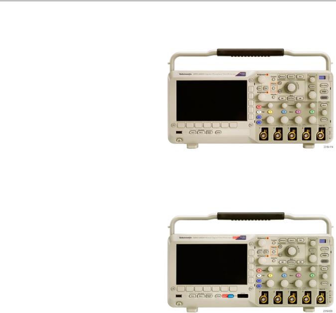
This manual describes the installation and operation of the following oscilloscopes:
DPO2024 |
DPO2014 |
DPO2012 |
MSO2024 |
MSO2014 |
MSO2012 |
Key Features
DPO2000 and MSO2000 series oscilloscopes can help you verify, debug, and characterize electronic designs. Key features include:
200 MHz and 100 MHz bandwidths
2 channel and 4 channel models
Sample rates up to 1 GS/s on all analog channels
1 M points record length on all channels
5,000 waveforms/second waveform capture rate
I2C, SPI, CAN, LIN, RS-232, RS-422, RS-485, and UART bus triggering and analysis (with the appropriate application module and model oscilloscope)
Wave Inspector controls for managing long record lengths, with zoom and pan, play and pause, search and mark
Large 178 mm (7 inch) WQVGA wide screen color display
Small and lightweight, at 140 mm (5.5 inch) deep and 3.6 kg (7 lbs, 14 oz)
FilterVu provides a variable low pass filter to block unwanted noise while still displaying high frequency events
USB flash drive port for quick and easy storage of measurement results
Direct printing to any PictBridge compatible printer
Ethernet port for remote programmability with the optional connectivity module
Video Out port to display the oscilloscope screen on an external monitor with the optional connectivity module
USB 2.0 Device port for direct PC control of the oscilloscope using USBTMC protocol
OpenChoice documentation software for simple transfer of screen shots and waveform data to a PC
National Instrument’s LabVIEW SignalExpress™ Tektronix Edition productivity and analysis software
Remote viewing and control with e*Scope
Remote control with VISA connectivity
 TekVPI Versatile Probe Interface supports active, differential, and current probes for automatic scaling and units MSO2000 series of mixed signal oscilloscopes also offer:
16 digital channels
Parallel bus triggering and analysis
Easy connection to your device-under-test through the convenient design of the P6316 digital probe
x |
DPO2000 and MSO2000 Series Oscilloscopes User Manual |
Preface
Conventions Used in This Manual
The following icons are used throughout this manual. |
|
|
|
|
Sequence Step |
Front panel power |
Connect power |
Network |
USB |
DPO2000 and MSO2000 Series Oscilloscopes User Manual |
xi |

Preface
xii |
DPO2000 and MSO2000 Series Oscilloscopes User Manual |
Installation
Installation
Before Installation
Unpack the oscilloscope and check that you received all items listed as standard accessories. The following pages list recommended accessories and probes, instrument options, and upgrades. Check the Tektronix Web site (www.tektronix.com) for the most current information.
Standard Accessories
|
|
Tektronix part |
|
Accessory |
Description |
number |
|
DPO2000 and MSO2000 Series |
English (Option L0) |
071-2319 XX |
|
Oscilloscopes User Manual |
|
|
|
French (Option L1) |
071-2320 XX |
||
|
|||
|
Italian (Option L2) |
071-2321 XX |
|
|
German (Option L3) |
071-2322 XX |
|
|
Spanish (Option L4) |
071-2323 XX |
|
|
Japanese (Option L5) |
071-2324 XX |
|
|
Portuguese (Option L6) |
071-2325 XX |
|
|
Simple Chinese (Option L7) |
071-2326 XX |
|
|
Traditional Chinese (Option L8) |
071-2327 XX |
|
|
Korean (Option L9) |
071-2328 XX |
|
|
Russian (Option L10) |
071-2329 XX |
|
DPO2000 and MSO2000 Series |
Electronic versions of documents, including |
063-4118 XX |
|
Oscilloscopes Documentation Browser |
the Programmer Manual and the Technical |
|
|
CD |
Reference. |
|
|
NI LabVIEW SignalExpress Tektronix Edition |
Productivity, analysis, and documentation |
063-3967 XX |
|
andTektronix OpenChoice Desktop PC |
software. |
|
|
Communications CDs |
|
|
|
Calibration certificate documenting |
|
—— |
|
traceability to national metrology institute(s), |
|
|
|
and ISO9001 quality system registration. |
|
|
|
Front panel overlay |
French (Option L1) |
335-2020-00 |
|
|
Italian (Option L2) |
335-2021-00 |
|
|
German (Option L3) |
335-2022-00 |
|
|
Spanish (Option L4) |
335-2023-00 |
|
|
Japanese (Option L5) |
335-2024-00 |
|
|
Portuguese (Option L6) |
335-2025-00 |
|
|
Simple Chinese (Option L7) |
335-2026-00 |
|
|
Traditional Chinese (Option L8) |
335-2027-00 |
|
|
Korean (Option L9) |
335-2028-00 |
|
|
Russian (Option L10) |
335-2029-00 |
DPO2000 and MSO2000 Series Oscilloscopes User Manual |
1 |

Installation
Standard Accessories (cont.)
|
|
Tektronix part |
Accessory |
Description |
number |
For DPO2000 and MSO2000 series: Probes |
One, 200 MHz, 1X/10X passive probe per |
P2221 |
|
channel |
|
For MSO2000 series: Digital probe |
One, 16-channel digital probe |
P6316 |
For MSO2000 series: Accessories pouch |
Pouch that attaches to the handle for carrying |
016-2008-00 |
|
probes and other accessories. |
|
Three year warranty |
For details, refer to the warranty in the front of |
—— |
|
this manual |
|
Power cord |
North America (Option A0) |
161-0348-00 |
|
Universal Euro (Option A1) |
161-0343-00 |
|
United Kingdom (Option A2) |
161-0344-00 |
|
Australia (Option A3) |
161-0346-00 |
|
Switzerland (Option A5) |
161-0347-00 |
|
Japan (Option A6) |
161-0342-00 |
|
China (Option A10) |
161-0341-00 |
|
India (Option A11) |
161-0349-00 |
|
No power cord or AC adapter (Option A99) |
—— |
2 |
DPO2000 and MSO2000 Series Oscilloscopes User Manual |

Installation
Optional Accessories
|
|
Tektronix part |
Accessory |
Description |
number |
DPO2EMBD |
The embedded serial triggering and analysis |
DPO2EMBD |
|
module enables triggering on packet level |
|
|
information on I2C and SPI serial buses, as |
|
|
well as bus views, bus decoding, search tools, |
|
|
and packet decode tables with timestamp |
|
|
information |
|
DPO2AUTO |
The automotive serial triggering and analysis |
DPO2AUTO |
|
module enables triggering on packet level |
|
|
information on CAN and LIN serial buses, as |
|
|
well as bus views, bus decoding, search tools, |
|
|
and packet decode tables with timestamp |
|
|
information |
|
DPO2COMP |
The computer triggering and analysis module |
DPO2COMP |
|
enables triggering on RS-232, RS-422, RS-485 |
|
|
and UART serial buses, search tools, bus |
|
|
views, bus decoding in hex, binary, and ASCII, |
|
|
and decode tables with timestamp information |
|
DPO2CONN |
The connectivity module adds an Ethernet port |
DPO2CONN |
|
for remote programmability and a Video Out |
|
|
port to display the oscilloscope screen on an |
|
|
external monitor |
|
NEX-HD2HEADER |
Adapter that routes the channels from a Mictor |
NEX-HD2HEADER |
|
connector to 0.1 inch header pins |
|
TPA-BNC |
TekVPI to TekProbe II BNC Adapter |
TPA-BNC |
TekVPI external power adapter |
Supplies external power to a TekVPI probe |
119 7465 XX |
Deskew pulse generator |
Deskew pulse generator and signal source |
TEK-DPG |
|
with TekVPI oscilloscope interface |
|
Power measurement deskew and calibration |
Converts TEK-DPG pulse generator output |
067-1686-00 |
fixture |
into a series of test point connections |
|
TEK-USB-488 Adapter |
GPIB to USB Adapter |
TEK-USB-488 |
Rackmount kit |
Adds rackmount brackets |
RMD2000 |
Soft transit case |
Case for carrying an oscilloscope |
ACD2000 |
Hard transit case |
Traveling hard case, which requires use of the |
HCTEK4321 |
|
soft transit case (ACD2000) |
|
DPO2000 and MSO2000 Series |
Service information on DPO2000 and |
071-2331 XX |
Oscilloscopes Service manual |
MSO2000 series oscilloscopes |
|
DPO2000 and MSO2000 Series Oscilloscopes User Manual |
3 |

Installation
Optional Accessories (cont.)
|
|
Tektronix part |
Accessory |
Description |
number |
DPO2000 and MSO2000 Series |
Describes how to install application modules in |
071-2330 XX |
Oscilloscopes Application Module Installation |
DPO2000 and MSO2000 series oscilloscopes |
|
The DPO2000 and MSO2000 series oscilloscopes work with multiple optional probes. (See page 8, Connecting Probes.) Check the Tektronix Web site (www.tektronix.com) for the most current information.
Related Documentation
Accessory |
Description |
Tektronix part number |
DPO2000 and MSO2000 Series |
Describes commands for remote control |
077-0097 XX |
Oscilloscopes Programmer Manual |
of the oscilloscope; available electronically |
|
|
on the Documentation Browser CD or for |
|
|
download from www.tektronix.com/manuals |
|
DPO2000 and MSO2000 Series |
Describes the oscilloscope specifications |
077-0096 XX |
Oscilloscopes Technical Reference |
and performance verification procedure; |
|
Manual |
available electronically on the Documentation |
|
|
Browser CD or for download from |
|
|
www.tektronix.com/manuals |
|
4 |
DPO2000 and MSO2000 Series Oscilloscopes User Manual |
Installation
Operating Considerations
DPO2000 and MSO2000 Series Oscilloscopes
Power Supply Input Voltage: 100 V to 240 V ± 10%
Power Supply Input Power Frequency: 50/60 Hz at 100 V to 240 V
400 Hz at 115 V
Power Consumption: 80 W maximum
Weight: 3.6 kg (7 lbs 14 oz), stand-alone oscilloscope
Height, including the feet but not the handle: 175 mm (6.885 inch)
Width: 377 mm (14.85 inch) |
DPO2000 series |
|
Depth: from the feet to the front of the knobs: 134 mm (5.3 inch)
Depth: from the feet to the front of the front cover: 139 mm (5.47 inch)
Clearance: 50 mm (2 inch)
Input Voltage (between the signal and reference): 300 VRMS CAT II
Installation Category II - for measurements performed on circuits directly connected to the low-voltage installation
Temperature:
Operating: 0 °C to +50 °C
Nonoperating: -20 °C to +60 °C
MSO2000 series
Humidity:
Operating: High: 40 °C to 50 °C, 10% to 60% RH
Operating: Low: 0 °C to 40 °C, 10% to 90% RH
Non-operating: High: 40 °C to 60 °C, 5% to 60% RH
Non-operating: Low: 0 °C to 40 °C, 5% to 90% RH
Altitude:
Operating: 3,000 m (9,842 ft)
Nonoperating Altitude: 12,000 m (39,370 ft)
DPO2000 and MSO2000 Series Oscilloscopes User Manual |
5 |

Installation
Random Vibration:
Operating: 0.31 GRMS, 5 - 500 Hz, 10 minutes per axis, 3 axes (30 minutes total)
Non-operating: 2.46 GRMS, 5 - 500 Hz, 10 minutes per axis, 3 axes (30 minutes total)
Pollution Degree: 2, Indoor use only
CAUTION. To ensure proper cooling, keep the sides and rear of the oscilloscope clear of obstructions.
P2221 Passive Probe
Input Voltage (between the signal and reference): 300 VRMS CAT II
Installation Category II - for measurements performed on circuits directly connected to the low-voltage installation
Temperature:
Operating: 0 °C to +50 °C (+32 °F to +122 °F)
Nonoperating: -55 °C to +75 °C ( -67 °F to +167 °F)
Pollution Degree: 2, Indoor use only
Humidity: 10% to 95% RH
MSO2000 Series Oscilloscope with a P6316 Digital Probe
Threshold Accuracy: ±(100 mV + 3% of threshold)
Threshold Range: ±20 V
Maximum nondestructive input signal to probe: ±40 V
Minimum signal swing: 500 mVpeak-to-peak
Input resistance: 101 kΩ
Input capacitance: 8.0 pF
Temperature:
Operating: 0 °C to +50 °C (+32 °F to +122 °F)
Nonoperating: -40 °C to +71 °C (-40 °F to +160 °F)
Altitude:
Operating: 3,000 m (9,843 ft) maximum
Nonoperating: 12,000 m (39,370 ft) maximum
Pollution Degree: 2, Indoor use only
6 |
DPO2000 and MSO2000 Series Oscilloscopes User Manual |

Installation
Humidity:
5% to 95% relative humidity
Cleaning
Inspect the oscilloscope and probes as often as operating conditions require. To clean the exterior surface, perform the following steps:
1.Remove loose dust on the outside of the oscilloscope and probes with a lint-free cloth. Use care to avoid scratching the clear glass display filter.
2.Use a soft cloth dampened with water to clean the oscilloscope. Use an aqueous solution of 75% isopropyl alcohol for more efficient cleaning.
CAUTION. To avoid damage to the surface of the oscilloscope or probes, do not use any abrasive or chemical cleaning agents.
DPO2000 and MSO2000 Series Oscilloscopes User Manual |
7 |
Installation
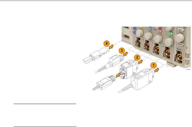
Connecting Probes
The oscilloscope supports probes with the following:
1.Tektronix Versatile Probe Interface (TekVPI)
These probes support two-way communication with the oscilloscope through on-screen menus and remotely through programmable support. The remote control is useful in applications like an ATE (automated test environment) where you want the system to preset probe parameters.
2.TPA-BNC Adapter
The TPA-BNC Adapter allows you to use Tek Probe II probe capabilities, such as providing probe power, and passing scaling and unit information to the oscilloscope.
NOTE. To use a TekVPI probe and a TPA-BNC adapter, connect a TekVPI external power adapter (Tektronix part number 119 7465 XX) to the side panel
Probe Power connector.
8 |
DPO2000 and MSO2000 Series Oscilloscopes User Manual |
Installation
3.Plain BNC Interfaces
Some probes use TekProbe capabilities to pass the waveform signal and scaling to the oscilloscope. Other probes
only pass the signal and there is no communication.
4.Digital Probe Interface (MSO2000 series only)
The P6316 probe provides 16 channels of digital (on or off state) information.
For more information on the many probes available for use with DPO2000 and MSO2000 series oscilloscopes, refer to www.tektronix.com.
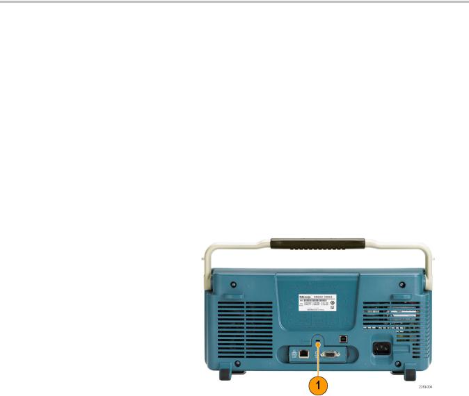
Securing the Oscilloscope
1.Use a standard laptop computer style security lock to secure your oscilloscope to your location.
This photo also shows the optional DPO2CONN module installed. The module provides an Ethernet port and a Video Out port for the oscilloscopes.
DPO2000 and MSO2000 Series Oscilloscopes User Manual |
9 |

Installation
Powering On the Oscilloscope
Ground the Oscilloscope and Yourself
Before pushing the power switch, connect the oscilloscope to an electrically neutral reference point, such as earth ground. Do this by plugging the three-pronged power cord into an outlet grounded to earth ground.
Grounding the oscilloscope is necessary for safety and to take accurate measurements. The oscilloscope needs to share the same ground as any circuits that you are testing.
To connect the power cord and power on the oscilloscope:
Quick Tips
If you are working with static sensitive components, ground yourself. Static electricity that builds up on your body can damage static-sensitive components. Wearing a grounding strap safely sends
static charges on your body to earth ground.
10 |
DPO2000 and MSO2000 Series Oscilloscopes User Manual |
 Loading...