


Tecumseh LAV30-50, V40-80, TVM125-220, HSK30-70, HH40-70 Manual
...Main Menu
TECUMSEH
T E C H N I C I A N ' S H A N D B O O K
This manual covers engine models:
ECV100 - 120, H22 - 80, HH40 - 70, HHM80, HM70 - 100,
HMSK70 - 110, HMXL70, HS40 - 50, HSK30 - 70, HSSK40 - 50,
HT30 - 35, HXL35, LAV30 - 50, LEV80 - 120, TNT100 - 120,
TVM125 - 220, TVXL170 - 220, TVS75 - 120, TVXL105 - 115,
V40 - 80, VH40 - 70, V60 - 70, VM70 - 100
Model numbers are located on the engine shroud.
3 TO 11 HP
4-CYCLE L-HEAD ENGINES

|
Main Menu |
CONTENTS |
|
|
|
CHAPTER 1 GENERAL INFORMATION......................................................................................................... |
1 |
ENGINE IDENTIFICATION ............................................................................................................................... |
1 |
INTERPRETATION OF MODEL NUMBER ...................................................................................................... |
1 |
SHORT BLOCKS .............................................................................................................................................. |
2 |
FUEL ................................................................................................................................................................. |
2 |
ENGINE OIL ..................................................................................................................................................... |
3 |
TUNE-UP PROCEDURE .................................................................................................................................. |
3 |
STORAGE ........................................................................................................................................................ |
4 |
CHAPTER 2 AIR CLEANERS ........................................................................................................................ |
5 |
GENERAL INFORMATION ............................................................................................................................... |
5 |
OPERATION ..................................................................................................................................................... |
5 |
COMPONENTS ................................................................................................................................................ |
5 |
TROUBLESHOOTING OR TESTING .............................................................................................................. |
5 |
SERVICE .......................................................................................................................................................... |
6 |
DISASSEMBLY PROCEDURE ......................................................................................................................... |
6 |
POLYURETHANE-TYPE FILTER ELEMENT ................................................................................................... |
6 |
PAPER-TYPE FILTER ELEMENT .................................................................................................................... |
6 |
CHAPTER 3 CARBURETORS AND FUEL SYSTEMS ................................................................................... |
7 |
GENERAL INFORMATION ............................................................................................................................... |
7 |
OPERATION ..................................................................................................................................................... |
8 |
FUEL PRIMERS ............................................................................................................................................... |
8 |
IMPULSE FUEL PUMPS .................................................................................................................................. |
9 |
FLOAT STYLE CARBURETORS ..................................................................................................................... |
9 |
DIAPHRAGM (PRESSURE DIFFERENTIAL) CARBURETORS ..................................................................... |
9 |
COMPONENTS .............................................................................................................................................. |
10 |
CARBURETOR IDENTIFICATION ................................................................................................................. |
11 |
DUAL SYSTEM CARBURETORS .................................................................................................................. |
11 |
SERIES 1 CARBURETORS ........................................................................................................................... |
11 |
SERIES 3 & 4 CARBURETORS..................................................................................................................... |
11 |
DIAPHRAGM CARBURETORS ..................................................................................................................... |
11 |
SERIES 6 CARBURETORS 4-CYCLE ........................................................................................................... |
12 |
SERIES 8 ........................................................................................................................................................ |
12 |
SERIES 9 ........................................................................................................................................................ |
12 |
SERIES 10 (EMISSION)................................................................................................................................. |
12 |
NON-TECUMSEH CARBURETORS -- DELLORTO CARBURETOR........................................................... |
12 |
ENGINE TROUBLESHOOTING CHART ....................................................................................................... |
13 |
CARBURETION TROUBLESHOOTING CHART ........................................................................................... |
14 |
TESTING ........................................................................................................................................................ |
15 |
SERVICE ........................................................................................................................................................ |
15 |
CARBURETOR PRE-SETS AND ADJUSTMENTS ....................................................................................... |
15 |
FINAL ADJUSTMENTS (NON-EMISSION ENGINES) .................................................................................. |
16 |
NON-ADJUSTABLE CARBURETOR ............................................................................................................. |
16 |
DISASSEMBLY PROCEDURE ....................................................................................................................... |
17 |
FLOAT STYLE CARBURETORS ................................................................................................................... |
17 |
DIAPHRAGM CARBURETORS ..................................................................................................................... |
19 |
FLOAT ADJUSTING PROCEDURE ............................................................................................................... |
19 |
INSPECTION .................................................................................................................................................. |
20 |
ASSEMBLY ..................................................................................................................................................... |
21 |
STANDARD SERVICE CARBURETORS ....................................................................................................... |
24 |
CHAPTER 4 GOVERNORS AND LINKAGE ................................................................................................. |
26 |
GENERAL INFORMATION ............................................................................................................................. |
26 |
OPERATION ................................................................................................................................................... |
26 |
INTERNAL COMPONENTS (VARIOUS STYLES) ......................................................................................... |
26 |
TROUBLESHOOTING .................................................................................................................................... |
26 |
ENGINE OVERSPEEDING ............................................................................................................................ |
27 |
ENGINE SURGING ........................................................................................................................................ |
27 |
SERVICE ........................................................................................................................................................ |
27 |
GOVERNOR ADJUSTMENT.......................................................................................................................... |
27 |
GOVERNOR ADJUSTMENT PROCEDURE FOR SHORT BLOCK INSTALLATIONS ................................. |
27 |
C Tecumseh Products Company |
i |
1998 |

Main Menu
GOVERNOR GEAR AND SHAFT SERVICE ................................................................................................. |
28 |
SPEED CONTROLS AND LINKAGE ............................................................................................................. |
29 |
CHAPTER 5 REWIND STARTERS................................................................................................................ |
35 |
GENERAL INFORMATION ............................................................................................................................. |
35 |
OPERATION ................................................................................................................................................... |
35 |
COMPONENTS .............................................................................................................................................. |
35 |
SERVICE ........................................................................................................................................................ |
35 |
ROPE SERVICE ............................................................................................................................................. |
35 |
RETAINER REPLACEMENT .......................................................................................................................... |
36 |
STYLIZED REWIND STARTER (TVS, HM, TVM, TVXL), AND STAMPED STEEL STARTER |
|
(HM, VM, TVM, TVXL) ............................................................................................................................... |
36 |
STYLIZED REWIND STARTER WITH PLASTIC RETAINER ........................................................................ |
37 |
STANDARD STAMPED STEEL AND CAST ALUMINUM STARTER (HM, VM) ............................................ |
38 |
VERTICAL PULL STARTER HORIZONTAL ENGAGEMENT TYPE .............................................................. |
39 |
VERTICAL PULL STARTER VERTICAL ENGAGEMENT TYPE ................................................................... |
40 |
CHAPTER 6 ELECTRICAL SYSTEMS ....................................................................................................... |
42 |
GENERAL INFORMATION ............................................................................................................................. |
42 |
OPERATION ................................................................................................................................................... |
42 |
STARTING CIRCUIT AND ELECTRIC STARTERS ....................................................................................... |
42 |
CHARGING CIRCUIT ..................................................................................................................................... |
42 |
CONVERTING ALTERNATING CURRENT TO DIRECT CURRENT ............................................................ |
43 |
HALF WAVE RECTIFIER SINGLE DIODE .................................................................................................... |
43 |
FULL WAVE RECTIFIER BRIDGE RECTIFIER ............................................................................................. |
43 |
COMPONENTS .............................................................................................................................................. |
43 |
BATTERY ........................................................................................................................................................ |
43 |
WIRING ........................................................................................................................................................... |
43 |
ELECTRICAL TERMS .................................................................................................................................... |
44 |
BASIC CHECKS ............................................................................................................................................. |
45 |
TROUBLESHOOTING ELECTRICAL STARTER CIRCUIT FLOW CHART .................................................. |
46 |
TROUBLESHOOTING ELECTRICAL CHARGING CIRCUIT FLOW CHART ............................................... |
47 |
TESTING PROCEDURE ................................................................................................................................ |
48 |
STARTING CIRCUIT ...................................................................................................................................... |
48 |
CHARGING CIRCUIT ..................................................................................................................................... |
48 |
VOLTAGE REGULATIONS ............................................................................................................................. |
56 |
LOW OIL SHUTDOWN SWITCHES............................................................................................................... |
56 |
SERVICE ........................................................................................................................................................ |
57 |
12 VOLT OR 120 VOLT ELECTRIC STARTERS WITH EXPOSED SHAFT ................................................. |
57 |
12 VOLT D.C. OR 120 VOLT A.C. ELECTRIC STARTERS WITH THE STARTER GEAR UNDER |
|
THE CAP ASSEMBLY ............................................................................................................................... |
57 |
INSPECTION .................................................................................................................................................. |
58 |
CHAPTER 7 FLYWHEEL BRAKE SYSTEMS ............................................................................................... |
59 |
GENERAL INFORMATION ............................................................................................................................. |
59 |
OPERATION ................................................................................................................................................... |
59 |
BOTTOM SURFACE SYSTEM ....................................................................................................................... |
59 |
INSIDE EDGE SYSTEM ................................................................................................................................. |
60 |
COMPONENTS .............................................................................................................................................. |
60 |
SERVICE ........................................................................................................................................................ |
61 |
FLYWHEEL REMOVAL .................................................................................................................................. |
61 |
BRAKE LEVER AND PAD .............................................................................................................................. |
61 |
IGNITION GOUNDOUT TERMINAL............................................................................................................... |
61 |
STARTER INTERLOCK SWITCH .................................................................................................................. |
62 |
CONTROL CABLE.......................................................................................................................................... |
62 |
BRAKE BRACKET REPLACEMENT.............................................................................................................. |
62 |
CHAPTER 8 IGNITION .................................................................................................................................. |
63 |
GENERAL INFORMATION ............................................................................................................................. |
63 |
OPERATION ................................................................................................................................................... |
63 |
SOLID STATE IGNITION SYSTEM (CDI) ...................................................................................................... |
63 |
MAGNETO IGNITION SYSTEM (POINTS) .................................................................................................... |
63 |
IDENTIFICATION OF TECUMSEH IGNITION SYSTEMS ............................................................................. |
64 |
COMPONENTS .............................................................................................................................................. |
64 |
IGNITION TROUBLESHOOTING .................................................................................................................. |
66 |
ii |
|

|
Main Menu |
TESTING PROCEDURE ................................................................................................................................ |
67 |
SERVICE ........................................................................................................................................................ |
68 |
SPARK PLUG SERVICE ................................................................................................................................ |
68 |
CONDITIONS CAUSING FREQUENT SPARK PLUG FOULING .................................................................. |
68 |
IGNITION TIMING PROCEDURE .................................................................................................................. |
68 |
SERVICE TIPS ............................................................................................................................................... |
71 |
CHAPTER 9 INTERNAL ENGINE AND CYLINDER ..................................................................................... |
72 |
GENERAL INFORMATION ............................................................................................................................. |
72 |
OPERATION ................................................................................................................................................... |
72 |
4-CYCLE ENGINE THEORY .......................................................................................................................... |
72 |
LUBRICATION SYSTEMS .............................................................................................................................. |
73 |
COUNTERBALANCE SYSTEMS ................................................................................................................... |
73 |
COMPONENTS .............................................................................................................................................. |
74 |
ENGINE OPERATION PROBLEMS ............................................................................................................... |
75 |
TESTING ........................................................................................................................................................ |
77 |
ENGINE KNOCKS .......................................................................................................................................... |
77 |
ENGINE OVERHEATS ................................................................................................................................... |
77 |
SURGES OR RUNS UNEVENLY ................................................................................................................... |
77 |
ENGINE MISFIRES ........................................................................................................................................ |
77 |
ENGINE VIBRATES EXCESSIVELY .............................................................................................................. |
78 |
BREATHER PASSING OIL ............................................................................................................................. |
78 |
EXCESSIVE OIL CONSUMPTION................................................................................................................. |
78 |
LACKS POWER ............................................................................................................................................. |
78 |
SERVICE ........................................................................................................................................................ |
79 |
DISASSEMBLY PROCEDURE ....................................................................................................................... |
79 |
CYLINDERS ................................................................................................................................................... |
81 |
CYLINDER HEADS ........................................................................................................................................ |
82 |
PISTONS, RINGS AND CONNECTING RODS ............................................................................................. |
82 |
CRANKSHAFTS AND CAMSHAFTS ............................................................................................................. |
84 |
VALVES .......................................................................................................................................................... |
85 |
CRANKCASE BREATHERS ........................................................................................................................... |
86 |
CYLINDER COVER, OIL SEAL, AND BEARING SERVICE .......................................................................... |
87 |
CRANKSHAFT BEARING SERVICE ............................................................................................................. |
88 |
COUNTERBALANCE SERVICE .................................................................................................................... |
89 |
FLYWHEEL SERVICE .................................................................................................................................... |
89 |
CHAPTER 10 ENGINE SPECIFICATIONS ................................................................................................... |
90 |
FOUR CYCLE TORQUE SPECIFICATIONS ................................................................................................. |
91 |
ENGINE SPECIFICATIONS STANDARD POINT IGNITION ......................................................................... |
93 |
SOLID STATE AND EXTERNAL IGNITION ................................................................................................... |
97 |
CHAPTER 11 EDUCATION MATERIALS AND TOOLS ............................................................................. |
102 |
DECIMAL / FRACTION CONVERSIONS ..................................................................................................... |
105 |
SEARS CRAFTSMAN CROSS REFERENCE SUPPLEMENT INCLUDED IN BACK OF BOOK |
|
iii
Main Menu
CHAPTER 1 GENERAL INFORMATION
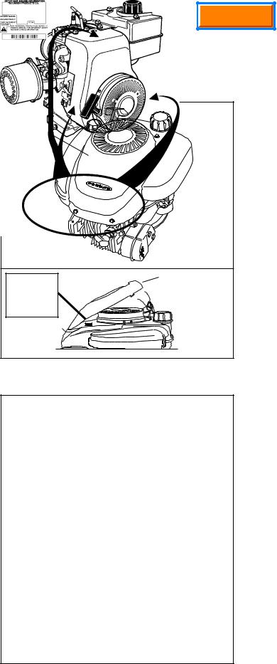
ENGINE IDENTIFICATION
Tecumseh engine model, specification, and serial numbers or (date of manufacture, DOM) are stamped into the blower housing or located on a decal on the engine in locations as illustrated (diag. 1 & 2).
NOTE: On some LEV engines, a cover bezel must be removed to provide access to the identification decal (diag. 1).
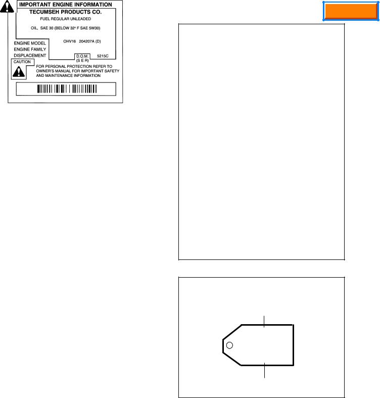
The engine identification decal also provides the applicable warranty code and oil recommendations (diag. 3).
Emissionized engines that meet the California Air Resource Board (C.A.R.B.) or the Environmental Protection Agency (E.P.A.) standards will include additional required engine information on the engine decal (diag. 3).
INTERPRETATION OF MODEL NUMBER
COVER BEZEL |
MODEL AND |
D.O.M. NUMBER |
DECAL |
LOCATED |
UNDER COVER |
(IF SO EQUIPPED) |
PRESS IN AND LIFT |
HERE TO RELEASE |
COVER |
Ç |
1 |
The first letter designation in a model number indicates basic type of engine.
V |
- Vertical Shaft |
LAV |
- Lightweight Aluminum Vertical |
VM |
- Vertical Medium Frame |
TVM |
- Tecumseh Vertical (Medium Frame) |
VH |
- Vertical Heavy Duty (Cast Iron) |
TVS |
- Tecumseh Vertical Styled |
TNT |
- Toro N’ Tecumseh |
ECV |
- Exclusive Craftsman Vertical |
TVXL - Tecumseh Vertical Extra Life |
|
LEV |
- Low Emissions Vertical |
H |
- Horizontal Shaft |
HS |
- Horizontal Small Frame |
HM |
- Horizontal Medium Frame |
HHM |
- Horizontal Heavy Duty (Cast Iron) Medium Frame |
HH |
- Horizontal Heavy Duty (Cast Iron) |
ECH |
- Exclusive Craftsman Horizontal |
HSK |
- Horizontal Snow King |
HS50 67355H SER 4091D
2
1
Main Menu
The number designations following the letter indicate the horsepower or cubic inch displacement.
The number following the model number is the specification number. The last three numbers of the specification number indicate a variation to the basic engine specification.
The serial number or D.O.M. indicates the production date.
Using model LEV115-57010B, serial 8105C as an example, interpretation is as follows:
LEV115-57010B is the model and specification number
LEV Low Emissions Vertical
115 Indicates a 11.5 cubic inch displacement
57010B is the specification number used for properly identifying the parts of the engine
8105C |
is the serial number |
8 |
first digit is the year of manufacture (1998) |
105indicates calendar day of that year (105th day or April 15, 1998)
Crepresents the line and shift on which the engine was built at the factory.
Engine Family: Engine Tracking Information
SHORT BLOCKS
New short blocks are identified by a tag marked S.B.H. (Short Block Horizontal) or S.B.V. (Short Block Vertical). Original model identification numbers of an engine should always be transferred to a new short block for correct parts identification (diag. 4).
THIS SYMBOL POINTS OUT IMPORTANT SAFETY INSTRUCTIONS WHICH IF NOT FOLLOWED COULD ENDANGER THE PERSONAL SAFETY OF YOURSELF AND OTHERS. FOLLOW ALL INSTRUCTIONS.
FUEL REGULAR UNLEADED
OIL, SAE 30 (BELOW 32oF SAE 5W30)
LEV115 57010B (D)
STP185U1G1RA
8105C
THIS ENGINE MEETS 1995-1998
CALIF. EMISSION REGULATOR FOR
ULGE ENGINES AS APPLICBLE
FUEL: REGULAR UNLEADED OIL: USE SEA30
LEV115 57010B (D)
STP185U1G1RA
8105C
3
SHORT BLOCK IDENTIFICATION TAG
SBV OR SBH IDENTIFICATION NUMBER
SBV-2316
SER 4291
SERIAL NUMBER
4
FUEL
Tecumseh strongly recommends the use of fresh clean unleaded regular gasoline in all engines. Unleaded gasoline burns cleaner, extends engine life and promotes better starting by reducing build-up of combustion chamber deposits.
REFORMULATED AND OXYGENATED FUELS
Reformulated fuels containing no more than 10% Ethanol, 15% MTBE, 15% ETBE or premium gasoline can be used if unleaded regular gasoline is not available. Leaded fuel may be used in countries where unleaded fuel is not available.
NEVER USE FUEL CONTAINING METHANOL.
2

Main Menu
ENGINE OIL
Use a clean, high quality detergent oil. Be sure original container is marked: A.P.I. service SF thru SJ. The use of multigrade oil may increase oil consumption under high temperature, high load applications.
NOTE: DO NOT USE SAE10W40 OIL.
For summer (above 32°F, 0 oC) use SAE 30 oil part # 730225 (1 quart, .946 liter container) in high temperature, high load applications.
S.A.E.10W30 is an acceptable substitute.
For winter (below 32°F, 0 oC) use S.A.E. 5W30 oil part # 730226 (1 quart, .946 liter container)
S.A.E.10W is an acceptable substitute.
S.A.E. 0W30 should only be used when ambient temperature is below 0oF, -18oC.
CAPACITIES: |
|
|
EUROPA MODELS |
|
|
Engine Model |
Oz. |
mL. |
|
Oz. |
mL. |
LAV30-50, TVS75-120, LEV80-120 |
21 |
630 |
Vantage |
21 |
630 |
ECV100-120, TNT100-120 |
21 |
630 |
Prisma |
21 |
630 |
V & VH50, 60, 70 |
27 |
810 |
Synergy |
21 |
630 |
TVM 125, 140 |
27 |
810 |
Synergy "55" |
27 |
810 |
TVM & TVXL 170, 195, 220 |
32 |
960 |
Spectra |
21 |
630 |
VM70, 80, 100 |
32 |
960 |
Futura |
21 |
630 |
VH100 |
50 |
1500 |
Centura |
21 |
630 |
H & HSK30, 35, HS & HSK40, 50 |
21 |
630 |
HTL |
21 |
630 |
H, HH & HSK50, 60, 70 |
19 |
570 |
BVS |
21 |
630 |
HM & HMSK70, 80, 100 |
26 |
720 |
BH Series |
21 |
630 |
|
|
|
Geo Tech Series 35-50 |
21 |
630 |
Oil Change Intervals. Change the oil after the first two (2) hours of operation and every 25 hours thereafter, or more often if operated under dusty or dirty conditions, extreme temperature, or high load conditions.
Oil Check. Check the oil each time the equipment is used or every 5 hours. Position the equipment so the engine is level when checking the oil.
 CAUTION: REMOVE THE SPARK PLUG WIRE BEFORE DOING ANY SERVICE WORK ON THE ENGINE.
Oil Change Procedure: Locate the oil drain plug. On some units this plug is located below the deck through the bottom of the mounting flange. Other units drain at the base of the engine above the deck or frame. If access to the drain plug is restricted by the equipment it may be necessary to drain the oil by tipping the mower in a position that would allow the oil to drain out of the fill tube.
On units that the drain plug is accessible, remove the plug and allow the oil to drain into a proper receptacle. Always make sure that drain oil is disposed of properly.
Once the oil is drained, reinstall the plug and fill the engine with new oil to the proper capacity.
TUNE-UP PROCEDURE.
The following is a minor tune-up procedure. When this procedure is completed, the engine should operate properly. Further repairs may be necessary if the engine's performance remains poor.
 CAUTION: REMOVE THE SPARK PLUG WIRE BEFORE DOING ANY SERVICE WORK ON THE ENGINE.
1.Service or replace the air cleaner as needed.
2.Inspect the level and condition of the oil and change or add oil as required.
3.Remove the blower housing and clean all dirt, grass or debris from the intake screen, cylinder head, cylinder cooling fins, carburetor, governor levers and linkage.
4.Make sure the fuel tank, fuel filter and fuel line are clean. Replace any worn or damaged governor springs or linkage. Make the proper governor adjustments and carburetor presets where required.
3

Main Menu
5.When replacing the spark plug, consult the parts breakdown for the proper spark plug to be used in the engine being serviced. Set the spark plug gap to .030" (.762 mm) and install the spark plug in the engine. Tighten the spark plug to 15 foot pounds of torque (20.4 Nm). If a torque wrench isn’t available, screw the spark plug in as far as possible by hand, and use a spark plug wrench to turn the spark plug 1/8 to 1/4 turn further if using the old spark plug, or 1/2 turn further if using a new spark plug.
6.Make sure all ignition wires are free of abrasions or breaks and are properly routed so they will not rub on the flywheel.
7.Properly reinstall the blower housing, gas tank, fuel line and air cleaner assembly if removed.
8.Make sure all remote cables are properly adjusted for proper operation. See chapter 4 under "Speed Controls and Linkage".
9.Reinstall the spark plug wire, add fuel and oil as necessary, and start the engine.
STORAGE: (IF THE ENGINE IS TO BE UNUSED FOR 30 DAYS OR MORE)
CAUTION: NEVER STORE THE ENGINE WITH FUEL IN THE TANK INDOORS , IN ENCLOSED POORLY VENTILATED AREAS WHERE FUEL FUMES MAY REACH AN OPEN FLAME, SPARK OR PILOT LIGHT AS ON A FURNACE, WATER HEATER, CLOTHES DRYER OR OTHER GAS APPLIANCE.
Gasoline can become stale in less than 30 days and form deposits that can impede proper fuel flow and engine operation. To prevent deposits from forming, all gasoline must be removed from the fuel tank and the carburetor. An acceptable alternative to removing all gasoline is adding a fuel stabilizer to the gasoline. Fuel stabilizer (such as Tecumseh's Part No. 730245) is added to the fuel tank or storage container. Always follow the mix ratio found on the stabilizer container. Run the engine at least 10 minutes after adding the stabilizer to allow it to reach the carburetor.
CAUTION:THE USE OF SOME ANTI-ICING ADDITIVES MAY CREATE A METHANOL FUEL BLEND. DO NOT USE ADDITIVESTHAT CONTAIN METHANOL. FUEL CONDITIONERSTHAT CONTAIN ISOPROPYL ALCOHOL IS RECOMMENDED.
Draining the Fuel System:
CAUTION: DRAIN THE FUEL INTO AN APPROVED CONTAINER OUTDOORS, AND AWAY FROM ANY  OPEN FLAME OR COMBUSTION SOURCE. BE SURE THE ENGINE IS COOL.
1.Remove all gasoline from the fuel tank by running the engine until the engine stops, or by draining the fuel tank by removing the fuel line at the carburetor or fuel tank. Be careful not to damage the fuel line, fittings, or fuel tank.
2.Drain the carburetor by pressing upward on the bowl drain (if equipped) which is located on the bottom of the carburetor bowl. On carburetors without a bowl drain, the carburetor may be drained by loosening the bowl nut on the bottom carburetor one full turn. Allow to completely drain and retighten the bowl nut being careful not to damage the bowl gasket when tightening.
3.If "Gasohol" has been used, complete the above procedure and then put one half pint of unleaded gasoline into the fuel tank and repeat the above procedure. If Gasohol is allowed to remain in the fuel system during storage, the alcohol content will cause rubber gaskets and seals to deteriorate.
Change Oil: If the oil has not been changed recently, this is a good time to do it.
Oil Cylinder Bore:
1.Disconnect the spark plug wire and ground the wire to the engine. Remove the spark plug and put 1/2 ounce (14 ml) of clean engine oil into the spark plug hole.
2.Cover the spark plug hole with a shop towel.
3.Crank the engine over slowly several times.
CAUTION: AVOID SPRAY FROM SPARK PLUG HOLE WHEN SLOWLY CRANKING ENGINE OVER.
4. Install the spark plug and connect the spark plug wire.
Clean Engine: Remove the blower housing and clean all dirt, grass or debris from the intake screen, cylinder head, cylinder cooling fins, carburetor, governor levers and linkage.
4
Main Menu
CHAPTER 2 AIR CLEANERS
GENERAL INFORMATION
The air cleaner is the device used to eliminate dust and dirt from the air supply. Filtered air is necessary to assure that abrasive particles are removed before entering the carburetor and combustion chamber. Dirt allowed into the engine will quickly wear the internal components and shorten the life of the engine.
Tecumseh engines use either a polyurethane or a papertype air filter system. A polyurethane pre-cleaner or a flocked screen may be used in conjunction with the main filter. Snow King® engines do not use an air filter.
Extremely dirty conditions may require more frequent filter cleaning or replacement.
OPERATION
The outer cover encapsulates the air filter element(s) and prevents large particles from entering the filter box. Air is filtered through the pre-cleaner or flocked screen (if equipped) and the polyurethane or paper filter element. Precleaners or flocked screens provide additional air cleaning capacity.
In Tecumseh's Kleen Aire®system, air is drawn in through a rotating screen or recoil cover to be centrifugally cleaned by the flywheel before the air is drawn into the air filter.
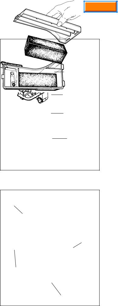
COMPONENTS (diag 1 & 2)
COVER
POLYURETHANE
WRAP
 SEALING NUTS
PAPER
ELEMENT
AIR CLEANER
BODY
1
The cover holds the filter element and prevents large debris from entering the filter element.
The polyurethane wrap pre-filter is used on XL or XL/C engine models with paper filter elements.
The paper or polyurethane filter element is the main filter to trap dust and dirt. Dry-type paper elements have treated paper folded for increased surface area and rubberlike sealing edges. The polyurethane filter uses an oil film to trap fine particles found in dust.
The flocked screen is used as an additional filter on XL or XL/C engine models that use a polyurethane filter element.
TROUBLESHOOTING OR TESTING
If the engine's performance is unsatisfactory (needs excessive carburetor adjustments, starts smoking abnormally, loses power), the first engine component to be checked is the air cleaner. A dirt restricted or an oil soaked element will cause noticeable performance problems. A polyurethane element may be cleaned following the service procedure listed under "Service" in this chapter. A papertype air filter should only be replaced. A paper-type element cannot have an oil film present on the paper. Follow the procedure listed in the "Service" section of this chapter for replacement. Re-try the engine after filter replacement or service. If the problem persists after filter service, see Chapter 9 under "Engine Operation Problems" for additional causes.
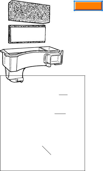
COVER
FOAM AIR CLEANER ELEMENT
BODY
FLOCKED SCREEN
2
5
Main Menu
SERVICE
Service on the polyurethane element (cleaning and oiling) is recommended every three months or every twenty five operating hours, whichever comes first. Extremely dirty or dusty conditions may require daily cleanings.
The paper filter element should be replaced at least once a year or more frequently if operated in dusty or dirty conditions.
NOTE: NEVER RUN THE ENGINE WITHOUT THE COMPLETE AIR CLEANER ASSEMBLY INSTALLED ON THE ENGINE. ALWAYS REPLACE THE FILTER ELEMENT WITH THE PROPER TECUMSEH ORIGINAL REPLACEMENT PART.
DISASSEMBLY PROCEDURE
1.Unlock the tabs or remove the screws, wingnuts or snaps holding the air cleaner cover in place.
2.Remove the hex nuts holding the element down if equipped. New nuts are supplied with a new filter and MUST be used for proper sealing.
3.Clean the excess contaminants out of the air cleaner body before removing the old element.
4.Remove the old element and the polyurethane precleaner if equipped.
5.On air cleaners that use a flocked screen under the polyurethane element, remove the air cleaner assembly from the carburetor before removing the flocked screen. This prevents dirt from entering the carburetor (diag 3).
6.Clean the inside of the cover and body, remove the old gasket between the carburetor and the air cleaner assembly.
7.Reinstall the air cleaner assembly using a new gasket.
8.Use the reverse procedure for reassembly. When installing the foam polyurethane pre-cleaner, make sure the seam is installed to the outside to prevent gaps between the paper element and the pre-cleaner.
FOAM
ELEMENT
1/2" (12.7 mm) FOAM
WITH FLOCKED
SCREEN
ATTACHED
AIR CLEANER
BODY
3
POLYURETHANE-TYPE FILTER ELEMENT
This type of air filter can be serviced when restricted with dust or dirt.Wash the filter or pre-cleaner in a liquid detergent and water solution until all the dirt is removed. Rinse in clear water to remove the detergent solution. Squeeze the element (do not twist) to remove the excess water. Wrap the element in a clean cloth and squeeze it (do not twist) until completely dry.
Re-oil the element by applying engine oil and squeezing it vigorously to distribute the oil. Roll the element in a cloth and squeeze it (do not twist) to remove the excess oil.
Clean the air cleaner housing and cover being careful not to allow dirt to fall into the carburetor or intake pipe.
PAPER -TYPE FILTER ELEMENT
Paper type air filter elements can only be serviced by replacement. Do not attempt to clean a paper filter element.
6
Main Menu
CHAPTER 3 CARBURETORS AND FUEL SYSTEMS
GENERAL INFORMATION
Tecumseh uses two basic types of carburetors, float and diaphragm type carburetors. Float type carburetors use a hollow float to maintain the operating level of fuel in the carburetor.Diaphragm type carburetors use a rubber-like diaphragm. One side is exposed to intake manifold pressure and the other side to atmospheric pressure.The diaphragm provides the same basic function (maintaining the proper fuel level in the carburetor) as the float.
An advantage of the diaphragm carburetor over the float style is that the diaphragm carburetor will allow the engine to operate at a greater degree of tiltability.
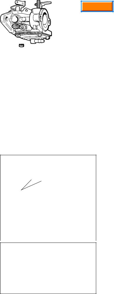
Tecumseh carburetors are identified by a manufacturing number and date code stamped on the carburetor as illustrated (diag. 1).
When servicing carburetors, use the engine model and specification number to obtain the correct carburetor part number. An alternate method to finding the correct carburetor part number is to use the manufacturing number and date code stamped on the carburetor and convert this number to a part number. In the carburetor section of the Master Parts Manual or Microfiche Catalog or computer parts look-up system. A cross reference chart will convert a carburetor manufacturing number to a Tecumseh part number.
Complete carburetor replacement may be accomplished with a standard service carburetor. A standard service carburetor is a basic carburetor that may require the use of original carburetor parts or additional new parts to adapt to the specification. An instruction sheet is provided with the new service carburetor or see “SERVICE” in this chapter.
ALTERNATE LOCATION
FOR MANUFACTURING
NUMBER
89 4F5
89 |
4F5 |
|
|
||
|
CARBURETOR |
|
MANUFACTURING |
DATE CODE |
|
1 |
||
NUMBER |
CAUTION: DRAIN THE FUEL INTO AN APPROVED CONTAINER OUTDOORS, AND AWAY FROM ANY
OPEN FLAME OR COMBUSTION SOURCE. BE SURE THE ENGINE IS COOL.
NOTE: Todays fuels can cause many problems in an engines performance, due to the fuels quality and short shelf life. Always check fuel as a primary cause of engine performance.
1.Remove the air filter, heater box, or air cleaner assembly if applicable to visually check that the choke shutter completely closes or check to see if fuel comes out of the main nozzle during priming.
2.If the fuel flow from the tank is adequate and no fuel is evident during priming, the carburetor will need to be removed for service. See “Service” in this chapter or consult the “Carburetion Troubleshooting” chart to diagnose carburetor symptoms. Improper fuel flow indicates the fuel, fuel line, filter or tank require cleaning or replacement.
3.Check the engine compression using a commercially available compression tester and follow the tester’s recommended procedure. Low compression, a dry spark plug, adequate fuel flow, and a known good functional carburetor indicates an internal engine problem exists. See under “Troubleshooting.”
4.A wet spark plug indicates fuel is being supplied by the carburetor. The engine may be flooded by a restricted air filter, carbon shorted or defective spark plug, excessive choking or over priming, improperly adjusted or defective carburetor. With the spark plug removed and a shop towel over the spark plug hole, turn the engine over slowly 3 or 4 times to remove excess gasoline from the engine cylinder.
CAUTION: KEEP ALL COMBUSTIVE SOURCES AWAY. AVOID THE SPRAY FROM THE SPARK PLUG HOLE WHEN CRANKING THE ENGINE OVER.
5.Replace the air filter if restricted or oil soaked. Replace the spark plug if questionable. Install the spark plug and high tension lead and try to start the engine.
6.If the engine floods and fails to start, the carburetor will require service. See the proceeding “Carburetion Troubleshooting” chart for additional causes. If the carburetor is functioning properly the problem may be ignition timing related. See “Troubleshooting" under "Ignition”.
7
Main Menu
OPERATION
In the “CHOKE” or “START” position, the choke shutter is closed and the only air entering the engine enters through openings around the shutter. As the engine starts to rotate, downward piston travel creates a low air pressure area (or vacuum) above the piston. Higher pressure (atmospheric) air rushes into the engine and fills this low pressure area. Since the majority of the air passage is blocked by the choke shutter, a relatively small quantity of air enters the carburetor at an increased speed.The main nozzle and both idle fuel discharge ports are supplying fuel due to the low air pressure in the engine intake. Maximum fuel flow through the carburetor orifices combined with the reduced quantity of air that passes through the carburetor, make a very rich fuel mixture which is needed to start a cold engine.
At engine IDLE speed, a relatively small amount of fuel is required to operate the engine.The throttle is almost completely closed. Fuel is supplied through the primary idle-fuel discharge orifice.
NOTE: Dual system carburetors do not have an idle circuit.
During INTERMEDIATE engine operation, a second orifice is uncovered as the throttle shutter opens, and more fuel is allowed to mix with the air flowing into the engine.
During HIGH SPEED engine operation, the throttle shutter is fully opened. Air flows through the carburetor at high speed. The venturi, which decreases the size of the air passage through the carburetor, further accelerates the air flow. This high speed movement of the air decreases the air pressure at the main nozzle opening. Fuel is forced out the main nozzle opening due to the difference in the air pressure on the fuel in the carburetor bowl and the reduced air pressure at the main nozzle opening.
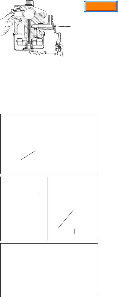
For the fuel to flow, the carburetor bowl must be either vented externally or internally. Some internally vented float style carburetors use a tygon tube and a vent within the air intake. This tube must be present for the carburetor to operate properly (diag. 2).
Air is bled into the main nozzle and through the air bleed located in the air horn. This mixes the fuel and air prior to the fuel leaving the main nozzle. Atomization occurs as the fuel mixture contacts the fast moving air stream. This mist then flows into the intake of the engine.
FUEL PRIMERS
Primers may be mounted remotely or as an integral part of the carburetor. The basic function of the primer is to supply a charge of air to the carburetor main well, or carburetor bowl. On diaphragm carburetors it displaces fuel directly into the carburetor venturi. This displaced fuel provides a rich mixture necessary for engines to start easily on the first or second attempt (diag. 3 & 4).
Primers must be vented either internally (a passage in the carburetor air horn prior to the venturi) or externally (through a hole in the primer bulb). The vent allows air to fill the primer bulb after the primer bulb is released. On diaphragm carburetors a one way valve in the body prevents the fuel from being forced back into the fuel tank.
Two different methods are used to prime float style carburetors, leg prime and bowl prime. The leg prime system is used only on the dual system carburetor. Air is forced into the center leg of the carburetor, which then forces an enriched mixture of fuel up the main nozzle.The bowl prime method is used on Series 6, 8, 9 and 10 carburetors and is distinguished by a stepped or hour glass shaped primer bulb. A good seal of the primer bulbs center lip is critical to assure that a full charge of air reaches the bowl. Also critical is a tight seal around the float bowl.
NOTE: Never re-use a bowl gasket.
TYGON TUBE
LOCATION
2
PRIMER BULB
PRIMER BULB
|
MAIN NOZZLE |
|
|
3 |
EMULSION |
MAIN JET |
|
TUBE |
4 |
||
|
|
|
BOWL PRIME
5
8
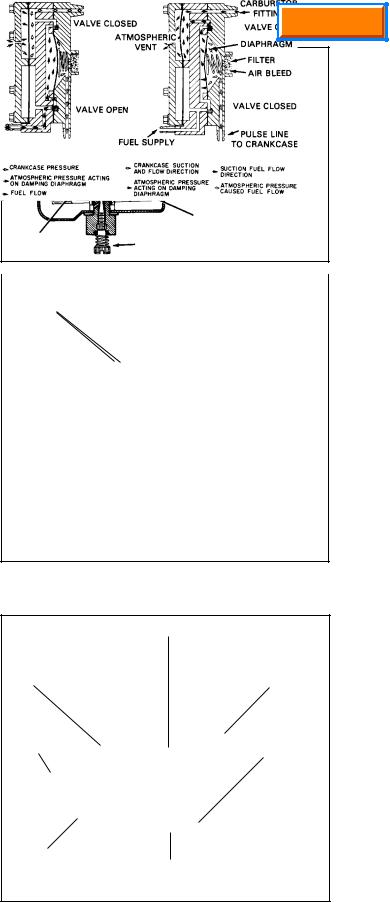
IMPULSE FUEL PUMPS
Impulse fuel pumps may either be mounted externally onto the carburetor fuel inlet or remotely mounted. These pumps are connected in the fuel line between the fuel supply and the carburetor or directly to the fuel inlet.
Impulse fuel pumps are operated by crankcase impulses created by the up and down movement of the piston. A hose called a pulse line connects the fuel pump diaphragm chamber to the crankcase and transmits these impulses to the pump diaphragm. The impulses actuate the diaphragm and flap valves to lift the fuel from the fuel tank to the carburetor (diag. 6).
FLOAT STYLE CARBURETORS
A float is used to maintain the operating volume of fuel in the carburetor bowl. As the fuel is used by the engine, the fuel volume in the carburetor bowl drops and the float moves downward. This allows the inlet needle valve to move off the sealing seat. Fuel flows by gravity or a pulse pump into the fuel bowl. As the fuel volume in the bowl again rises, it raises the float. This upward float motion moves the inlet needle valve to the closed position. When the needle contacts the seat, the fuel flow is stopped. The tapered end of the inlet needle varies the fuel flow rate so that the fuel volume in the carburetor bowl will remain constant (diag. 7). The float height is set according to the service procedure.
DIAPHRAGM (PRESSURE DIFFERENTIAL) CARBURETORS
This type of carburetor uses a rubber-like diaphragm which is exposed to intake manifold pressure on one side and to atmospheric pressure on the other.Tecumseh diaphragm carburetors use the diaphragm as a metering device. As the intake manifold pressure decreases due to downward piston travel, the atmospheric pressure on the vented side of the diaphragm moves the diaphragm against the inlet needle. The diaphragm movement overcomes the spring tension on the inlet needle and moves the inlet needle off the seat. This permits the fuel to flow through the inlet valve to maintain the correct fuel volume in the fuel chamber. The inlet needle return spring closes the inlet valve when the pressure on the diaphragm equalizes or a pressure higher than atmospheric exists on the intake side (upward piston travel). The diaphragm meters a correct fuel volume in the fuel chamber to be delivered to the mixing passages and discharge ports (diag. 8).
A main or idle adjustment needle may be replaced by an internally fixed jet on some models.
The main nozzle contains a ball check valve. The main purpose of this ball check is to eliminate air being drawn down the main nozzle during idle speeds and leaning the idle mixture.
An advantage of the diaphragm carburetor over the float system is that the diaphragm carburetor increases the angle that the engine may be operated at.
Main Menu
6
IDLE AND |
IDLE AIR |
MAIN AIR |
|
PROGRESSION |
BLEED |
||
BLEED |
|||
HOLES |
|
||
|
|
||
|
|
CHOKE |
|
THROTTLE |
|
SHUTTER |
|
|
|
||
SHUTTER |
|
|
|
INLET NEEDLE |
|
|
AND SEAT |
|
IDLE |
|
|
ADJUSTMENT |
|
|
|
FLOAT |
|
MAIN NOZZLE |
MAIN |
|
EMULSION |
||
ADJUSTMENT |
||
TUBE |
||
7 |
||
|
CHECK BALL
THROTTLE |
CHOKE |
|
SHUTTER |
||
SHUTTER |
||
|
||
IDLE |
NEEDLE AND |
|
ADJUSTMENT |
||
SEAT ASSEMBLY |
||
|
MAIN
ADJUSTMENT DIAPHRAGM
8
9

Main Menu
COMPONENTS
CHOKE SHAFT AND LEVER
CHOKE SHUTTER
MAIN NOZZLE
*INLET FITTING SCREEN
*INLET FITTING
*INLET SEAT GASKET
*INLET NEEDLE SEAT AND SPRING ASSEMBLY
*DIAPHRAGM GASKET
*DIAPHRAGM
ATMOSPHERIC VENT HOLE
Check shaft for binding. Position shutter opening towards inlet fitting side or air horn.
Blow air through passage.
Part of inlet fitting. If fuel is restricted, clean or replace fitting.
Bulb primer models have Viton* one way valve, in or behind fitting.
Remove and replace.
Proper installation of assembly is important.
Gasket and diaphragm sequence may be reversed on some models. Head of rivet must touch inlet needle. Rivet is hooked into inlet needle control lever on some models.
Hole must be clean. On models with bulb primer, vent hole is very small and is located off center.
9
|
|
|
|
|
|
|
|
METERING ROD OR PIN IN |
|
|
|
|
|
|
FUEL TRANSFER PASSAGE |
|
|
|
|
|
NOTE: On models which have |
|
|
|
|
||
metering rods, do not install idle |
BALL PLUG |
|
|
(DO NOT REMOVE) |
|
|
|
||||||
adjustment screw with carburetors |
|
|
|
|
||
|
|
|
|
|
|
|
upside down, as pin will obstruct |
CUP PLUG |
|
|
|
|
|
movement of adjustment screw |
|
|
|
|
||
|
|
|
|
|
|
|
causing damage |
IDLE AND INTERMEDIATE |
|
|
|
|
|
|
FUEL TRANSFER PASSAGE |
|
|
|
|
|
IDLE AND MAIN FUEL PICK UP ORFICE *NON METALLIC ITEMS - CAN BE DAMAGED
BY HARSH CARBURETOR CLEANERS
|
Loosen screw until it just clears |
|
IDLE SPEED ADJUSTMENT |
throttle lever, then turn screw in one |
|
|
turn. |
|
|
|
|
|
|
|
MAIN NOZZLE |
Removable on emission carbs. non- |
|
metallic only. |
||
(EMULSION TUBE) |
||
|
||
CHOKE SHAFT |
|
|
AND LEVER |
Check shaft for binding position |
|
|
opening to bottom of air horn. |
|
CHOKE PLATE |
|
|
|
||
|
|
|
HIGH SPEED |
Blow air through passage. Do not |
|
AIR BLEED |
remove restrictor if present. |
|
|
|
|
INLET |
|
|
FITTING |
|
|
*INLET NEEDLE |
|
|
Proper installation is important. |
||
AND SEAT |
|
|
*FLOAT BOWL |
|
|
|
||
Replace. |
||
GASKET |
|
|
FLOAT |
|
|
SHAFT INLET |
|
|
NEEDLE CLIP |
Must hook over float tab. |
|
(If Present) |
|
|
|
IDLE FUEL TRANSFER PASSAGE
AND ANNULAR GROOVE
FLOAT |
Check float for leaks or dents. Clean |
|
bowl and adjust float level position |
||
|
||
FLOAT BOWL |
gasket or gaskets. |
|
|
*GASKET |
If the carburetor is used on a 20° slant |
|
|
|
engine, the engine must be in its |
|
|
|
normal 20° slanted position for ad- |
|
|
|
justment. |
|
|
|
|
|
|
NUT AND MAIN ADJUSTMENT SEAT |
Check needle for damage and "O" |
|
|
ring for cracks. Clean all passages |
|
|
|
*MAIN ADJUSTMENT SCREW AND |
|
||
in nut with compressed air. |
|
|
|
"O" RING SEAL |
|
||
|
|
|
|
|
10 |
||
10
Main Menu
CARBURETOR IDENTIFICATION |
|
Tecumseh has a variety of carburetors. To help identify |
|
these carburetors here are some simple procedures to |
|
follow. |
|
DUAL SYSTEM CARBURETORS |
|
|
|
The easiest way to identify the dual system carburetor is |
|
by the presence of a large primer bulb located on the side |
|
of the carburetor.The absence of adjustment needles help |
|
to identify the carb as well. The dual system carburetor is |
|
used on 4-cycle vertical crankshaft rotary mower engines. |
|
(diag. 11). |
|
|
11 |
SERIES 1 CARBURETORS |
|
|
|
|
|
Series 1 carburetors come in a variety of styles. They are |
|
used on both 2 and 4 cycle vertical and horizontal shaft |
|
engines in the 2 through 7 h.p. range. It is a float style |
|
carburetor with a smaller venturi than the Series 3 and 4 |
|
carburetors. Some will have an adjustable idle and main |
|
and others will have a fixed main with an adjustable idle. |
|
There are also some fixed speed applications that will only |
|
have a fixed main system and the idle system will not be |
12 |
drilled. (diag. 12). |
|
|
|
NOTE: Emissionized carburetors will have a fixed jet.
SERIES 3 & SERIES 4 CARBURETORS
Series 3 and 4 carburetors are generally used on 8 through 12.5 horsepower 4-cycle engines.The venturi size of these carburetors are larger than Series 1 and Dual System Carburetors.The quickest way to identify these carburetors is by the presence of bosses on each side of the idle mixture screw. To identify the Series 3 from a Series 4, view the carburetor from the throttle end.The Series 3 has
(1)screw securing the throttle plate and the Series 4 uses
(2)screws. (diag. 13 - 15)
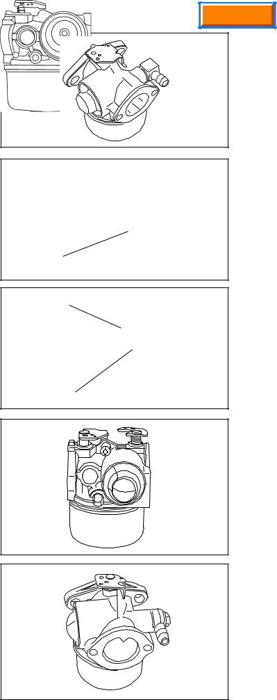
DIAPHRAGM CARBURETORS
The diaphragm carburetors are unique.These carburetors can be operated at a more severe angle than float style carburetors.They still require that the fuel supply be located in a position that allows it to be gravity fed. Its most distinctive feature is the lack of a fuel bowl. (diag. 16).
NOTE: Emissionized carburetors will have a fixed jet.
BOSSES
13
SERIES 3 |
14 |
SERIES 4 |
15 |
|
|
|
16
11
SERIES 6 CARBURETORS 4-CYCLE
Series 6 carburetors are used on 2 and 4-cycle engines. They have a larger venturi than the dual system carburetor and use a simple fixed idle system. Series 6 carburetors used on both vertical and horizontal applications are nonadjustable.The 4 cycle version pictured has a stepped primer bulb. (diag. 17).
SERIES 8
The Series 8 carburetor has both a fixed main and idle circuit. The fixed idle system uses a restricted jet that meters the fuel. The idle restrictor jet will be capped to prevent access unless removed.The fixed main jet is part of the bowl nut. A ball plug is visible from the bottom, which seals the metering passage. This carburetor also has a serviceable main nozzle emulsion tube. It also has a stepped primer bulb to assist in starting. (diag. 18)
SERIES 9
The Series 9 carburetor uses the same body as the Series 8 but has a simple fixed idle system, identical to the one used on the Series 6 carburetor. It has the idle discharge port located at the 7 o'clock position on the throttle end of the carburetor. Identify this carburetor by the stepped primer bulb, the presence of a non-drilled idle mixing well and a serviceable main nozzle emulsion tube. (diag. 19)
SERIES 10 (EMISSION)
The Series 10 carburetor is identical to the Series 8 carburetor with the addition of a choke to assist in cold weather starts. It also has a fixed idle and main. The idle restrictor jet will be capped to prevent access unless the cap is removed. The fixed main jet is part of the bowl nut. A ball plug is visible from the bottom, which seals the metering passage.This carburetor also has a serviceable main nozzle emulsion tube and a stepped primer bulb to assist in starting. (diag. 20)
NON-TECUMSEH CARBURETORS
DELLORTO CARBURETOR
The Dellorto carburetor is similar to the dual system carburetor. It has no adjustments and has a primer assist start. It has a noncorrosive float and the needle is viton tipped, eliminating the viton seat found in the dual system carburetor. The angle of the fuel inlet is adjustable and attached to the carburetor body with a banjo bolt. This carburetor is used on some TVS rotary lawnmower engines.
CAPPED FIXED
JET
MIXING WELL CAST BUT NOT MACHINED
IDLE JET
CAST BUT NOT
MACHINED
Main Menu
17
18
19
20
21
12

Main Menu
ENGINE
TROUBLESHOOTING
Engine Will Not Start
Check For Spark
|
Wet |
|
|
|
Dry |
|
|
|
Check If Spark Plug Is Wet or Dry |
|
|
||||
|
|
|
|
|
|
|
|
|
|
|
|
|
|
|
|
|
|
|
|
|
|
|
|
|
|
|
|
|
|
|
|
Defective Spark Plug
Check Fuel Supply and Fuel
Cap Vent
Restricted Air Filter
Restriction in Fuel System
(filter, screen)
|
|
|
|
|
|
|
|
|
|
|
|
Improper or Stale Fuel |
|
Carburetion Problem |
|||
|
|
|
|
|
|
|
|
|
|
|
|
Sheared or Partially Sheared Flywheel Key
Poor Compression
Carburetion Problems Due to Flooding, Over Priming, etc.
Ignition System
13

|
|
|
|
|
|
|
|
|
|
|
|
|
|
|
|
|
|
Main Menu |
|||
|
|
|
|
|
|
CARBURETION |
|
|
|
|
|
|
|
|
|
|
|||||
|
|
|
|
|
|
|
|
|
|
|
|
|
|
|
|
||||||
|
|
|
|
|
TROUBLESHOOTING |
|
|
|
|
|
|
|
|
||||||||
|
|
|
|
|
|
|
|
|
|
|
|
|
|
|
|
|
|
|
|
|
|
|
START |
|
|
|
|
IDLE |
|
|
ACCELERATE |
HIGH SPEED |
|
|
|||||||||
|
|
|
|
|
|
|
|
|
|
|
|
|
|
|
|
|
|
|
|
|
|
|
|
|
|
|
|
|
|
|
|
|
|
|
|
Will |
|
|
|
|
|
|
|
|
|
|
|
|
|
|
|
|
Idles |
|
|
|
|
Not |
|
|
|
|
|
|
|
AIR SYSTEM |
|
Fuel Leak |
|
|
|
|
Idles with |
Hunts - |
Will Not |
Over Rich |
|
Run at |
|
Hunts at |
Runs with |
|
Engine |
|
|||
Hard |
at |
Engine |
Will Not |
|
|
Needle |
Erratic |
Fast - |
Acceler- |
Accelera- |
|
High |
Low |
High |
Needle |
|
Over- |
|
|||
PROBLEMS |
Starting |
Carburetor |
Floods |
Idle |
Rich Idle |
Closed |
Idle |
Lean |
ate |
tion |
|
Hesitates |
Speed |
Power |
Speed |
Closed |
|
speeds |
|
||
Plugged Air Filter |
Á |
|
|
Á |
Á |
|
|
|
|
Á |
Á |
|
Á |
Á |
|
|
|
|
|
|
|
Leaky Carburetor |
|
|
|
Á |
|
|
|
Á |
Á |
|
|
|
Á |
|
|
|
|
|
|
Á |
|
|
|
|
|
|
|
|
|
|
|
|
|
|
|
|
|
|
|
|
|
|
|
Gasket |
|
|
|
|
|
|
|
|
|
|
|
|
|
|
|
|
|
|
|
|
|
|
|
|
|
|
|
|
|
|
|
|
|
|
|
|
|
|
|
|
|
|
|
Throttle or Choke |
Á |
|
|
Á |
|
|
|
Á |
Á |
|
|
|
|
|
Á |
Á |
|
|
|
Á |
|
Shafts Worn |
|
|
|
|
|
|
|
|
|
|
|
|
|
|
|||||||
Choke Not |
Á |
|
|
|
|
|
|
|
|
|
|
|
|
|
|
|
|
|
|
|
|
Functioning |
|
|
|
|
|
|
|
|
|
|
|
|
|
|
|
|
|
|
|
|
|
Properly |
|
|
|
|
|
|
|
|
|
|
|
|
|
|
|
|
|
|
|
|
|
Plugged |
|
Á |
Á |
|
|
|
|
|
|
|
|
|
|
|
|
|
|
|
|
|
|
|
|
|
|
|
|
|
|
|
|
|
|
|
|
|
|
|
|
|
|
|
|
Atmospheric Vent |
|
|
|
|
|
|
|
|
|
|
|
|
|
|
|
|
|
|
|
|
|
|
|
|
|
|
|
|
|
|
|
|
|
|
|
|
|
|
|
|
|
|
|
Restricted |
Á |
|
|
Á |
Á |
|
|
Á |
|
Á |
|
|
Á |
|
|
Á |
|
|
|
|
|
Air Bleed |
|
|
|
|
|
|
|
|
|
|
|
|
|
|
|
|
|
|
|
|
|
Damaged or |
|
Á |
|
|
|
|
|
Á |
Á |
|
|
|
|
|
|
Á |
|
|
|
Á |
|
Leaky "O" Rings |
|
|
|
|
|
|
|
|
|
|
|
|
|
|
|
|
|||||
DIAPHRAGM |
|
|
|
|
|
|
|
|
|
|
|
|
|
|
|
|
|
|
|
|
|
SYSTEM |
|
|
|
|
|
|
|
|
|
|
|
|
|
|
|
|
|
|
|
|
|
PROBLEM |
|
|
|
|
|
|
|
|
|
|
|
|
|
|
|
|
|
|
|
|
|
|
|
|
|
|
|
|
|
|
|
|
|
|
|
|
|
|
|
|
|
|
|
Damaged |
Á |
Á |
|
Á |
|
|
|
|
Á |
|
|
|
|
|
Á |
|
Á |
|
|
|
|
|
|
|
|
|
|
|
|
|
|
|
|
|
|
|
|
|
|
|
|
|
|
Diaphragm |
|
|
|
|
|
|
|
|
|
|
|
|
|
|
|
|
|
|
|
|
|
|
|
|
|
|
|
|
|
|
|
|
|
|
|
|
|
|
|
|
|
|
|
Stuck or Dirty Ball |
|
|
|
Á |
|
|
Á |
|
|
Á |
|
|
Á |
|
|
Á |
|
|
|
|
|
|
|
|
|
|
|
|
|
|
|
|
|
|
|
|
|
|
|
|
|
|
|
Check |
|
|
|
|
|
|
|
|
|
|
|
|
|
|
|
|
|
|
|
|
|
|
|
|
|
|
|
|
|
|
|
|
|
|
|
|
|
|
|
|
|
|
|
Diaphragm |
Á |
|
|
|
|
|
|
|
|
|
|
|
|
|
|
|
|
|
|
|
|
|
|
|
|
|
|
|
|
|
|
|
|
|
|
|
|
|
|
|
|
|
|
Upside Down |
|
|
|
|
|
|
|
|
|
|
|
|
|
|
|
|
|
|
|
|
|
|
|
|
|
|
|
|
|
|
|
|
|
|
|
|
|
|
|
|
|
|
|
FUEL SYSTEM |
|
|
|
|
|
|
|
|
|
|
|
|
|
|
|
|
|
|
|
|
|
PROBLEM |
|
|
|
|
|
|
|
|
|
|
|
|
|
|
|
|
|
|
|
|
|
|
|
|
|
|
|
|
|
|
|
|
|
|
|
|
|
|
|
|
|
|
|
Plugged Tank |
Á |
|
|
|
|
|
|
|
|
Á |
|
|
Á |
Á |
Á |
|
|
|
|
|
|
Filter or Vent |
|
|
|
|
|
|
|
|
|
|
|
|
|
|
|
|
|||||
Restricted |
Á |
|
|
Á |
|
|
|
Á |
|
Á |
|
|
Á |
Á |
|
Á |
|
|
|
|
|
Fuel Pick-up |
|
|
|
|
|
|
|
|
|
|
|
|
|
|
|
|
|
|
|
|
|
Idle Port |
|
|
|
Á |
|
|
|
Á |
|
|
|
|
|
|
|
|
|
|
|
|
|
Restricted |
|
|
|
|
|
|
|
|
|
|
|
|
|
|
|
|
|
|
|
||
Needles |
Á |
|
|
Á |
Á |
Á |
Á |
|
Á |
|
|
|
Á |
Á |
Á |
Á |
|
Á |
|
||
AdjustmentDamaged |
|
|
|
|
|
|
|
|
|
|
|
|
|
|
|
|
|
|
|
||
Height |
|
|
Á |
|
|
|
|
Á |
|
Á |
|
Á |
|
|
Á |
Á |
|
|
|
|
|
Incorrect Float |
|
|
|
|
|
|
|
|
|
|
|
|
|
|
|
|
|
|
|
|
|
Restricted |
Á |
|
|
|
|
|
|
|
|
Á |
|
|
Á |
Á |
Á |
Á |
|
|
|
|
|
Main Nozzle |
|
|
|
|
|
|
|
|
|
|
|
|
|
|
|
|
|
|
|
|
|
|
|
|
|
|
|
|
|
|
|
|
|
|
|
|
|
|
|
|
|
|
|
Dirty, Stuck |
Á |
Á |
Á |
Á |
|
|
|
Á |
|
|
|
|
|
|
Á |
Á |
|
|
|
|
|
|
|
|
|
|
|
|
|
|
|
|
|
|
|
|
|||||||
Needle and Seat |
Á |
|
|
|
|
|
|
|
|
|
|
|
Á |
|
|
|
|
|
|
||
Fuel Inlet Plugged |
|
|
|
|
|
|
|
|
|
|
|
|
|
|
|
|
|
|
|
|
|
|
|
|
|
|
|
|
|
|
|
|
|
|
|
|
|
|
|
|
|
|
|
14

Main Menu
TESTING
1.After repeated efforts to start the engine using the procedure listed in the operator’s manual fail, check for spark by removing the high tension lead and the spark plug. Install a commercially available spark plug tester and check for spark. If spark is evident and acceptable, proceed to step 2. If no or weak spark, see Chapter 8 under "Testing".
2.Visually inspect the spark plug for a wet condition indicating the presence of gasoline in the cylinder.
3.If the spark plug is dry, check for restrictions in the fuel system before the carburetor. If the spark plug is wet, continue with step # 7. Check to see if the fuel cap vent is open. With a proper draining receptacle, remove the fuel line clamp on the carburetor fuel inlet and pull the fuel line off the fitting to examine the fuel flow and fuel condition.
4.Remove the air cleaner element or air cleaner assembly to visually check that the choke shutter completely closes or check to see if fuel comes out from the main nozzle during priming.
5.If the fuel flow is adequate and no fuel is evident during priming, the carburetor will need to be removed for service. See “Service” in this chapter or consult the “Carburetion Troubleshooting” chart if other problems exist. Improper fuel flow indicates the fuel, fuel line, filter or tank require cleaning or replacement.
6.Check the engine compression using a commercially available compression tester and follow the tester’s recommended procedure. Low compression, a dry spark plug, adequate fuel flow, and a known good functional carburetor indicates an internal engine problem exists. See Chapter 9 under “Engine Operation Problems.”
7.A wet spark plug indicates fuel is being supplied by the carburetor. The engine may be flooded by a restricted air filter, carbon shorted or defective spark plug, excessive choking or over priming, improperly adjusted or defective carburetor, or the wrong ignition timing.With the spark plug removed and a shop towel over the spark plug hole, turn the engine over slowly 3 or 4 times to remove excess gasoline from the engine cylinder.
CAUTION: KEEP ALL COMBUSTIVE SOURCES AWAY. AVOID THE SPRAY FROM THE SPARK PLUG HOLE WHEN CRANKING THE ENGINE OVER.
8.Replace the air filter if restricted or oil soaked. Replace the spark plug if questionable. Install the spark plug and high tension lead and retry starting the engine.
9.If the engine floods and fails to start, the carburetor may require service.See the preceding “Carburetion Troubleshooting” chart for additional causes. If the carburetor is functioning properly the problem may be ignition timing related. See Chapter 8 under “Ignition Troubleshooting.”
SERVICE
CARBURETOR PRE-SETS AND ADJUSTMENT
NOTE: EMISSION GRADE CARBURETORS HAVE FIXED IDLE AND MAIN JETS.THE ABSENCE OFTHE ADJUSTING SCREW INDICATES A FIXED JET OR RESTRICTOR AND NO ADJUSTMENT IS NECESSARY. THE IDLE RESTRICTOR ON THE SERIES 8 CARBURETOR APPEARS AS AN ADJUSTABLE SCREW. THIS IS NOT ADJUSTABLE AND MUST REMAINTIGHT FOR PROPER OPERATION.
Before adjusting any mixture screws the necessary carburetor presets should be made. Check for the proper governor adjustments as outlined in Chapter 4. Identify the correct carburetor model and manufacturer to find locations of the high and low speed adjustment screws. Check the throttle control bracket for proper adjustment allowing a full choke shutter position. See Chapter 4 under "Speed Controls and Linkage". Check to see if the normal maintenance procedures have been performed (oil changed, fresh fuel, air filter replaced or clean). Consult microfiche card #30 to find the correct R.P.M. settings for the engine, or consult Service Bulletin #107 for the revised safety specification for rotary type power lawn mowers. Start the engine and allow it to warm to operating temperature. The carburetor can now be adjusted.
15

PRE-SETS AND ADJUSTMENTS
(TECUMSEH AND WALBRO CARBURETORS)
NOTE: OVERTIGHTENING WILL DAMAGE THE TAPER PORTION OF THE NEEDLE. All adjustments should be made with the carburetor in the operating position.
Turn both the main and idle mixture adjusting screws in (clockwise) until finger tight.
Now back the mixture screws out (counterclockwise) to obtain the pre-set figure in the chart shown at right.
Main Menu
Tecumseh Carburetors
Engine Model |
Main Pre-set |
Idle Pre-set |
|
All models with float-type |
1-1/2 turn |
1 turn |
|
carburetors |
|||
|
|
||
|
|
|
|
All models with diaphragm-type |
1 turn |
1 turn |
|
carburetors |
|||
|
|
||
|
|
|
|
Walbro Carburetors |
|
||
Carburetor Model Number |
|
|
|
|
|
|
|
LMH |
1-1/2 turn |
1-1/2 turn |
|
|
|
|
|
WHG & LME |
1-1/4 turn |
1-1/4 turn |
|
|
|
|
|
LMK |
Fixed |
1 turn |
|
|
|
|
|
FINAL ADJUSTMENTS (NON EMISSION ENGINES)
Start the engine and allow it to warm up to normal operating temperature (3 - 5 minutes). Set the speed control to the HIGH or FAST position. From the recommended preset position, turn the main mixture adjustment screw in (clockwise) slowly until the engine begins to run erratic (lean). Note the position of the screw. Now, turn the screw out (counterclockwise) until the engine begins to run erratic (rich). Turn the screw in (clockwise) midway between these two positions. This will be the best setting. (diag. 21, 22 & 23).
Set the speed control to the IDLE or SLOW position. Adjust the idle mixture screw following the same procedure used to adjust the main mixture adjustment screw.
TECUMSEH CARBURETORS
SERIES 1 |
SERIES 3 & 4 |
DIAPHRAGM |
|
|
MAIN MIXTURE |
IDLE MIXTURE |
|
MAIN MIXTURE |
IDLE MIXTURE |
|
|
|
|
|
|
|||||
IDLE MIXTURE |
|
|
SCREW |
SCREW |
|
|
||
|
SCREW |
SCREW |
|
|
MAIN MIXTURE |
|
||
SCREW |
21 |
|
22 |
SCREW |
23 |
|||
|
|
|||||||
If further adjustment is required, the main adjustment should be made under a loaded condition.
If the engine stops or hesitates while engaging the load (lean), turn the main mixture adjusting screw out (counterclockwise) 1/8 turn at a time, testing each setting with the equipment under load, until this condition is corrected.
If the engine smokes excessively (rich), turn the main adjusting screw in (clockwise) 1/8 turn at a time, testing each setting with the equipment under load, until this condition is corrected.
After the main mixture screw is set, move the speed control to the IDLE or SLOW position. If the engine does not idle smoothly, turn the idle mixture screw 1/8 turn either in (clockwise) or out (counterclockwise) until engine idles smoothly.
Recheck the high and low R.P.M. setting and adjust as necessary.
NON-ADJUSTABLE CARBURETORS
DUAL SYSTEM AND SERIES 6 |
SERIES 8 |
SERIES 9 |
SERIES 10 |
CHOKE |
|
|
MIXING WELL |
|
|
|
|
|
|
|
|
|
CAST BUT |
|
|
|
|
NOT |
|
|
|
|
MACHINED |
|
|
NON-ADJUSTABLE |
CAPPED FIXED |
IDLE JET |
CAPPED IDLE |
27 |
PRIMER NO CHOKE 24 |
JET |
25 CAST BUT NOT MACHINED 26 |
RESTRICTOR |
16
Main Menu
DISASSEMBLY PROCEDURE
NOTE: Engines which are identified as compliant with CARB (California Air Resources Board) or EPA (US Environmental Protection Agency) regulations can NOT be changed from the factory unless specifically authorized.
FLOAT STYLE CARBURETORS
1.Note or mark the high and low mixture adjusting screws to aid in reassembly (if applicable). Remove the high speed adjusting screw, bowl nut, and float bowl. Remove the idle mixture screw assembly.
2.Note the position of the spring clip on the inlet needle and float, the long end of the clip must face toward the choke end of the carburetor. Remove the float hinge pin with a needlenose pliers. Some carburetors use a float dampening spring to aid the inlet valve in maintaining a steady position during rough service applications. Note the position of the hooks before removing the float hinge pin (diag. 28).
3.Remove the float, clip, and inlet needle.
4.Remove the inlet needle seat using a #4 crochet hook, a wire or paper clip with a 3/32" (2.38 mm) hook end as shown. Push the hook through the hole in the center of the seat to remove it. (diag. 29).
5.Note or mark the action of the choke and throttle shutters, and/or the hook points of the choke or throttle return spring, or seal retainer springs located on the top of the choke and/or throttle shaft. Remove the throttle shutter, throttle shaft, choke shutter, springs and choke shaft by removing the screw(s) that attach the throttle or choke shutter to the shaft inside the air horn.
6.Remove the primer bulb (if equipped) by grasping it with a pliers and pulling and twisting out of the body. Remove the retainer by prying and lifting it out with a screwdriver. Do not re-use the old bulb or retainer (diag. 30).
7.Some Tecumseh float style carburetors have a damper spring which is installed as shown. (diag. 31)
LONG END |
|
|
|
|
CLIP |
|
|
|
|
OPEN END |
|
|
|
||||
OF CLIP |
|
OF CLIP |
|||
|
|
|
|
|
THROTTLE |
|
|
|
|
|
END |
CHOKE |
|
|
|||
END |
|
|
|||
28
3/32" (2.38 mm)
HOOK END
29
30
POINTS TOWARD
THE CHOKE END
31
17

8.Remove all welch plugs if cleaning the carburetor. Secure the carburetor in a vise equipped with protective jaws. Use a small chisel sharpened to a 1/8" (3.175 mm) wide wedge point. Drive the chisel into the plug to pierce the metal, then push down on the chisel to pry the plug out of the hole (diag. 32).
NOTE: DO NOT REMOVE ANY BALL OR CUP PLUGS (diag. 33).
9.Note the direction of the inlet fitting. If necessary the inlet fitting can be removed. (See page 24).
10.The main nozzle on Series 8 and Series 9 carburetors can be removed by pressing the tube outward from the venturi thru the center leg. This nozzle is nonmetallic and has an "O" ring seal on the top and bottom end of the tube. Do not remove a main nozzle that is made of brass from any Tecumseh carburetor. These are pressed in at the factory to a specific depth.When removing the nozzle, the top "O" ring may not come out with the tube. The "O" ring must be removed and placed on the nozzle before it is placed back into the center leg or it will not seal properly. (diag. 34)
The main nozzle on some Walbro carburetors are removable for service. If you remove it, a service nozzle with the under cut fuel passage must be installed or problems will occur (diag. 35).
Main Menu
SMALL CHISEL |
|
PRY OUT |
PIERCE PLUG WITH TIP |
|
|
PLUG |
WELCH PLUG TO BE |
|
|
|
REMOVED |
DO NOT ALLOW |
ABOUT 1/8" |
CHISEL POINT |
(3.175 mm) |
TO STRIKE |
WIDE |
CARBURETOR |
|
BODY OR |
|
CHANNEL |
|
REDUCER |
|
|
SMALL CHISEL |
|
32 |
DO NOT REMOVE PLUGS
BRASS OR BALL PLUG
BALL PLUG
IDLE FUEL PASSAGE
REDUCTION ROD INSIDE
33
NOT USED ON SERIES 7
OR VECTOR CARBS.
"O" RING
ON TOP OF STEP (IN GROOVE)
"O" RING IN GROOVE
"O" RING
34
SERVICE MAIN NOZZLE
REUSABLE
ORIGINAL MAIN NOZZLE
DO NOT REUSE
35
18
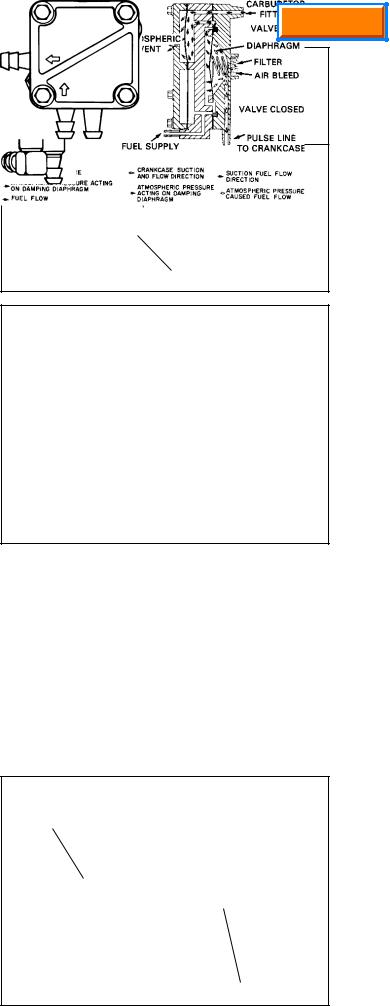
Diaphragm Carburetors
1.Remove the screws holding the diaphragm cover on.
2.Remove the cover, gaskets, and diaphragm noting or marking the sequence or location to aid in reassembly.
NOTE: If a "F" designation on the choke end of the carburetor is present, place the diaphragm on first, then the gasket and cover. If no "F" is present, the gasket goes first.
3.Note or mark the high and low mixture adjustment screws. Remove the screw assemblies.
4.Note or mark the action of the choke and throttle shutters and the hook points of the choke or throttle return spring or seal retainer springs located on the top of the choke or throttle shaft. Remove the throttle shutter, throttle shaft, choke shutter, springs and choke shaft by removing the screw or screws that attach the throttle or choke shutter to the shaft inside the air horn.
5.Use a 9/32" (7.144 mm) thin wall socket to unscrew and remove the inlet needle and seat assembly (diag. 36).
6.Note and mark the direction of the inlet fitting. If necessary the inlet fitting can be removed by pulling with a pliers or vise. Some diaphragm carburetors have a strainer as an integral part of the fuel fitting. If the strainer is lacquered or cannot be cleaned, the fitting must be replaced.
7.Remove all welch plugs if cleaning the carburetor.
Secure the carburetor in a vise equipped with protective jaws. Use a small chisel sharpened to a 1/8" (3.175 mm) wide wedge point. Drive the chisel into the plug to pierce the metal, then push down on the chisel to pry the plug out of the hole.
NOTE: DO NOT REMOVE ANY BALL OR CUP PLUGS.
IMPULSE FUEL PUMP
To service, disassemble the pump by removing the four
(4) screws. Clean all parts with a solvent and install a new kit which consists of a coil spring, gaskets and diaphragms (diag. 37 & 38).
FLOAT ADJUSTING PROCEDURE
All Tecumseh carburetors with an adjustable float require the correct float height to achieve the proper operation and easy engine starts.To check the float height, hold the carburetor in an upside down position. Remove the bowl nut, float bowl, and "O" ring. Place an 11/64" (4.36 mm) diameter drill bit across the top of the carburetor casting on the opposite side and parallel to the float hinge pin (diag. 39). The float must just touch the drill bit when the bit is flush with the edge of the float. If the float is too high or too low, adjust the height by bending the tab accordingly. If the required adjustment is minor, the tab adjustment may be made without removing the float and carefully inserting a small bladed screwdriver to bend the tab.
Float sticking can occur due to deposits or when the fuel tank is filled for the first time, this condition can be quickly corrected by loosening the carburetor bowl nut one full turn. Turn the bowl 1/4 turn in either direction, then return the bowl to its original position and tighten the bowl nut.
Main Menu
"F" DESIGNATION
"F"
DIAPHRAGM FIRST NOT GASKET 36
37
OLD STYLE |
NEW STYLE |
38 |
|
||
|
|
|
11/64" (4.36 mm) DRILL BIT
RIM 39
19
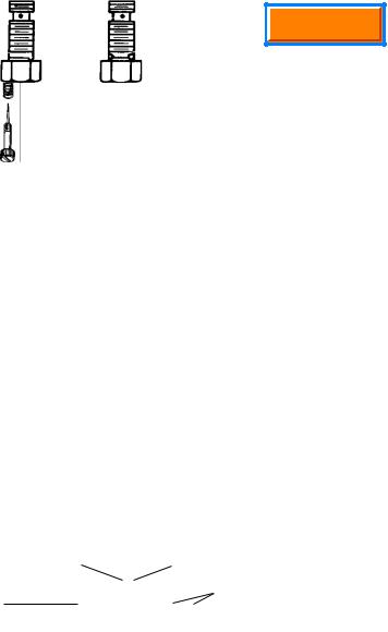
Main Menu
INSPECTION
After careful disassembly of the carburetor and the removal of all non metallic parts, the carburetor body and all other metallic parts should be cleaned with solvent, or commercial carburetor cleaner, no longer than 30 minutes. Use compressed air and soft tag wire to clean internal carburetor passages.To do a proper cleaning job, the welch plugs must be removed to expose the drilled passages.
NOTE: The nylon check balls used in some diaphragm carburetors are not serviceable. Nylon can be damaged if subjected to harsh cleaners for prolonged periods.
Throttle and Choke
Examine the throttle lever and shaft, choke lever and shaft, and carburetor body at the bearing points and holes into which the linkage is fastened, and replace if worn or damaged. Any looseness in these areas can cause dirt to enter the engine and cause premature wear. If dust seals are present, these should be positioned next to the carburetor body.
Idle and High Speed Mixture Adjusting Screw |
|
|
|
|
|
|
|
|
|
Examine the idle mixture needle tip and tapered surface |
|
|
|
|
|
|
RETAINER NUT |
|
|
|
|
|
|
|
|
|
|
||
|
|
|
|
|
|
"O" RING |
|
|
|
|
|
|
|
|
|
|
|
||
for damage.The tip and tapered surface of the needle must |
|
|
|
|
|
|
BRASS WASHER (used to protect the |
||
|
|
|
|
|
|
||||
not show any wear or damage at all. If either is worn or |
|
|
|
|
|
|
"O" ring from the spring) |
|
|
damaged, replace the adjusting needle. Tension is |
|
|
|
|
|
|
SPRING |
|
|
|
|
|
|
|
|
|
|
||
|
|
|
|
|
|
|
|
|
|
maintained on the screw with a coil spring. Examine and |
|
|
|
|
|
|
HIGH SPEED |
|
|
replace the “O” ring seal if damaged (diag. 40). |
|
|
|
|
|
|
|
|
|
|
|
|
|
|
|
ADJUSTMENT SCREW |
40 |
||
Examine the tapered surface of the high speed mixture |
|
|
|
|
|
|
|
|
|
|
|
|
|
|
|
|
|
|
|
needle. If the tapered surface is damaged or shows wear, |
|
|
|
|
|
|
|
|
|
replace the needle (non-emissioned). Some Tecumseh |
|
|
|
|
|
|
|
|
|
|
|
|
|
|
|
|
|
|
|
carburetors use serviceable jet main nozzles. These are |
|
|
|
|
|
|
|
|
|
identified as being non-metallic. |
|
|
|
|
|
|
|
|
|
|
|
|
|
|
|
|
IDLE FUEL |
FUEL-INLET |
|
|
FUEL- |
|
|
|
|
|
TRANSFER |
PORTS |
|
Fuel Bowl Retaining Nut |
METERING |
|
|
|
|
|
PASSAGE |
|
|
|
PORT |
|
|
|
|
|
|
|
|
The retaining nut contains the transfer passage or metering |
|
ONE-HOLE TYPE TW0-HOLE TYPE |
41 |
||||||
|
|
|
|
|
|
|
|
|
|
jet through which fuel is delivered to the high speed and |
|
|
|
|
|
|
|
|
|
idle circuit of the carburetor. If a problem occurs with the |
|
|
|
|
|
|
|
|
|
idle circuit, examine the small fuel passage in the annular groove in the retaining (metering) nut. This passage must be clean for the proper transfer of fuel into the idle metering circuit. Torque retaining nut to 50 in. lbs. (5.65 Nm) when reinstalling.
There are two different types of bowl nuts that are used on adjustable main, float style carburetors. One type has one fuel metering port at the bottom of the nut, and the other has two fuel inlet ports at the bottom of the nut. This difference relates to calibration changes to the carburetor and is dependent on the application (diag. 41).
NOTE: DO NOT INTERCHANGE BOWL NUTS.
The fuel inlet ports must be free of any debris to allow proper fuel flow.
Fuel Bowl, Float, Needle and Seat
The float bowl must be free of dirt and corrosion. Clean with solvent or carburetor cleaner.
Examine the float for damage. Check the float hinge bearing surfaces for wear, as well as the tab that contacts the inlet needle. Replace any damaged or worn parts.
The needle and seat should be replaced if any fuel delivery problems are experienced (flooding or starvation). Sealing problems with the inlet needle seat may not be visible, so replacement is recommended.
Diaphragms, Pulse Pumps, and Primer Bulbs
Inspect diaphragms, gaskets, and primer bulbs for cracks, tears, hardness or brittleness. Replace if necessary.
20
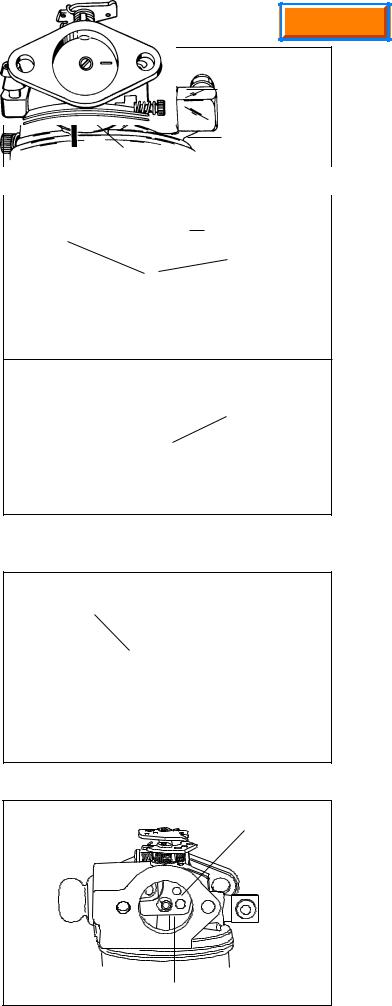
ASSEMBLY
Welch Plugs
To install a new welch plug after cleaning the carburetor, secure the carburetor in a vise equipped with protective jaws. Place the welch plug into the receptacle with the raised portion up. With a punch equal to, or greater than the size of the plug, merely flatten the plug. Do not dent or drive the center of the plug below the top surface of the carburetor. After installation of the welch plug, seal the outer diameter with finger nail polish or equivalent (diag. 42).
Throttle Shaft and Plate
When reassembling, it is important that the lines or lettering on the throttle plate are facing out when in the closed position. Position throttle plate with two lines at 12 and 3 o’clock. If the throttle plate has only one line, the line should be positioned in the 12 o’clock position on Series 1, 6, 8, and 9 carburetors, and positioned in the 3 o’clock position on Series 3 and 4 carburetors (diag. 43 & 44).
Test the operation of the throttle and return spring (if equipped). If binding occurs, correct by loosening screws and repositioning throttle plate.
Always use a new screw(s) when reinstalling the throttle shutter (Tecumseh screws are treated with dry-type adhesive to secure them in place).
NOTE: NEVER REUSE OLD SCREWS.
Choke Shaft and Plate
The choke plate is inserted into the air horn of the carburetor in such a position that the flat surface of the choke is down. Choke plates will operate in either direction. Make sure it is assembled properly for the engine. Test the operation of the choke and return spring function if equipped (diag. 45).
Always use a new screw(s) when reinstalling the choke shutter as the screws are treated with dry-type adhesive to secure them in place.
NOTE: NEVER REUSE OLD SCREWS.
The choke shaft and plate must be in the closed position prior to tightening the screws. Hard starting may be due to insufficient choking action because of a misaligned choke plate. Correct by readjusting the choke plate to close completely. Note the cut-out position of choke shutter if applicable.
Fuel Inlet Fitting
Support the carburetor body with a wood block to avoid damage to other parts. Use a bench vise or press to install the fitting squarely. Insert the tip into the carburetor body, coat the exposed portion of the shank with Loctite grade A, then press it in until the shoulder contacts the carburetor body.
Main Menu
FLAT END PUNCH
NEW WELCH PLUG
|
SAME OR LARGER |
|
DIAMETER OF |
|
PLUG |
|
42 |
|
|
|
SERIES 1, 6, 8, 9, 10 |
THROTTLE |
THROTTLE LEVER |
PLATE |
TWELVE O'CLOCK |
|
|
|
POSITION |
43
SERIES 3 AND 4
THREE O'CLOCK
POSITION
44
CHOKE PLATE
FLAT |
|
DOWN |
45 |
CHOKE PLATE
FLAT SIDE DOWN |
46 |
|
21
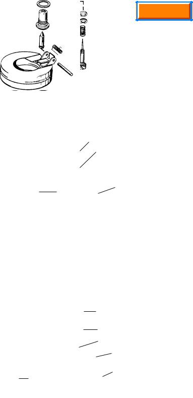
Main Menu
High and Low Speed Adjusting Screw, Main Nozzle
When reassembling, position the coil spring on the adjusting screws, followed by the small brass washer and the “O” ring seal. Turn the high speed adjustment screw in approximately one turn into the bowl retainer nut to make an assembly (diag. 47).
On 2-7 hp. engines that use carburetors which have the metering rod in the idle circuit (carburetor should rattle when shaking), make certain that the idle adjustment screw is installed when the carburetor is in an upright position or the needle will damage the metering rod, adjustment screw and carburetor casting.
Some carburetors are of the fixed main type and would not have a high speed adjusting screw.
Inlet Needle and Seat
On float type carburetors, make sure the seat cavity is clean. Moisten the seat with oil and insert the seat with the grooved side down and away from the inlet needle. Press the seat into the cavity using a flat punch close to the diameter of the seat, making sure it is firmly seated (diag. 48).
The inlet needle hooks onto the float tab by means of a spring clip.To prevent binding, the long, straight end of the clip should face the air intake end of the carburetor as shown (diag. 49).
On diaphragm carburetors the inlet needle and seat assembly are installed by using a socket to tighten the assembly until seated.
Needle and Seat Pop-OffTest
To test the pop-off pressure, remove the carburetor from the engine. Be sure to drain any fuel into an approved container. Invert the carburetor and remove the float bowl. Place a drop of an oil based product such as WD-40 on the tip of the needle valve. Using a commercially available 0-30 psi pump and gauge, attach the pumps hose to the carburetor inlet. Apply approximately 6 psi or until the needle pops off the seat.The needle should seat at 1.5 psi or greater for a minimum of 5 minutes. If the minimum 1.5 psi cannot be maintained for this period of time, then service to the needle and seat is required.
Float Installation
Reinstall the inlet needle and float into the carburetor.The long end of the spring or clip on the inlet needle must point toward the air intake end of the carburetor. If a float dampening spring is used, reassemble using the following steps (diag. 50).
|
|
RETAINER NUT |
|
|
|
|
|
|
"O" RING |
|||||
|
|
|
|
|
||||||||||
|
|
|
|
|
|
|
BRASS WASHER |
|||||||
|
|
|
|
|
|
|
||||||||
|
|
|
|
|
|
|
|
|
|
|
|
|
||
|
|
|
|
|
|
|
|
|
|
|
|
|
|
SPRING |
|
|
|
|
|
|
|
|
|
|
|
|
|
||
TORQUE NUT TO |
|
|
|
|
|
|
HIGH SPEED |
|||||||
50 IN. LBS. (5.65 Nm) |
|
|
|
|
|
|
ADJUSTMENT SCREW |
|||||||
|
|
|
|
|
|
|
|
47 |
||||||
|
|
|
|
|
|
|
|
|
|
|
||||
|
|
|
|
|
|
|
|
|
|
5/32" FLAT PUNCH |
||||
DRIVE IN UNTIL |
|
|
|
|
|
|
SEAT |
|||||||
|
|
|
|
|
|
|
||||||||
SEAT RESTS ON |
|
|
|
|
|
|
|
|||||||
BODY SHOULDER |
|
|
|
|
|
|
|
|||||||
INLET NEEDLE |
|
|
|
|
|
|
INSERT THIS |
|||||||
|
|
|
|
|
|
FACE FIRST |
||||||||
SEATS AT THIS |
|
|
|
|
|
|
||||||||
|
|
|
|
|
|
|
||||||||
POINT |
48 |
|||||||||||||
|
|
|
|
|
|
|
|
|||||||
|
LONG END |
|
|
|
|
|
CLIP |
|||||||
|
|
|
|
|
|
|||||||||
|
|
|
|
|
|
OPEN END |
||||||||
|
|
|
|
|||||||||||
|
|
|
|
|
|
|
|
|||||||
|
OF CLIP |
|
|
|||||||||||
|
|
|
OF CLIP |
|||||||||||
|
|
|
|
|
|
|
|
|
|
|||||
|
|
|
|
|
|
|
|
|
|
|
THROTTLE |
|||
|
|
|
|
|
|
|
|
|
|
|
|
|
|
END |
|
|
CHOKE |
|
|
|
|
|
|
|
|||||
|
|
END |
49 |
|||||||||||
|
|
|
|
|
|
|
|
|||||||
|
|
|
|
|
|
|
|
|
|
|
|
|
|
|
|
|
|
|
|
|
|
|
|
|
|
|
|
|
WASHER |
|
|
|
|
|
|
|
|
|
|
|
|
|
|
INLET SEAT |
|
|
|
|
|
|
|
|
|
|
|
|
|
|
INLET NEEDLE |
|
|
|
|
|
|
|
|
|
|
|
|
|
|
FLOAT SPRING |
|
|
|
|
|
|
|
|
|
|
|
|
|
|
HINGE PIN |
FLOAT |
|
|
|
|
|
|
|
|||||||
|
|
|
|
|
|
|
|
50 |
||||||
|
|
|
|
|
|
|
|
|
|
|
|
|
|
|
1.Place the float upside down.
2.Position the spring on the float with the long end around and to the back side of the float’s center back tang.The ends must point toward the choke end of the carburetor. Hook the inlet needle clip on the inside float tang so the clip end points to the choke end of the carburetor (diag. 50).
3.Place the float, float spring, clip and inlet needle in position between the hinge legs of the carburetor. As the float assembly nears the hinge legs, wind the outside end of the spring so it goes to the outside of the leg (counterclockwise looking from the choke end).
22
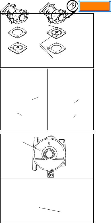
4.Install the hinge pin from the opposite hinge leg. The bowl gasket must be positioned over the end of the spring (diag. 51).
5.Set the proper float height. See “Float Adjusting Procedure” in this chapter.
Diaphragm Assembly
The rivet head on the diaphragm must always face toward the inlet needle valve. On carburetors with an “F” cast into the carburetor flange as illustrated, the diaphragm goes next to the carburetor body. Other diaphragm carburetors have the gasket located between the diaphragm and carburetor body. Install the cover retaining screws and tighten (diag. 52).
Fuel Bowl And Bowl Nut
Whenever a carburetor bowl is removed for service, the fuel bowl “O” ring must be replaced. For easier installation, lubricate the “O” ring with a small amount oil.
Install the float bowl by placing the detent portion opposite of the hinge pin. Make sure the deepest end of the bowl is opposite of the inlet needle. The bowl has a small dimple located in the deepest part. The purpose of this dimple is to minimize the chances of the float sticking to the bottom of the bowl caused by stale fuel (diag. 53).
On some fixed jet (non-adjustable) and adjustable carburetors, a fibered washer is required between the carburetor bowl and the bowl retaining nut.
Occasionally, on engines equipped with the dual system carburetor, some rich starting conditions have occurred when the engine is warm.This condition can be corrected by inserting a non-metallic spacer in the center leg of the carburetor, as shown (part # 632158). This spacer is designed to reduce the amount of prime charge in the main nozzle area for better starting under warm engine conditions. It can only be used on Dual System carburetors and does not lean out the carburetor mixture. (diag. 54) This spacer must be reinstalled if originally equipped in the carburetor.
Impulse Fuel Pump
The diaphragms must be installed against the center body with the gaskets against the outside covers.The parts are designed so they cannot be misassembled without damage (diag. 54).
To test the unit, assemble the carburetor to the engine, leaving the fuel line from the pump off. Use a different fuel tank remotely placed above the carburetor to provide gravity fuel flow to the carburetor inlet to run the engine while testing the pump. Make sure fuel is available in both fuel tanks and that the original fuel tank's fuel line is connected to the fuel pump inlet. Place the pump outlet line in a proper draining receptacle. With the pulse line connected from the engine crankcase to the pump and the engine running, a definite fuel flow should result at the pump outlet.
If the flow is erratic or intermittent, the pump needs repair or replacement.
Main Menu
GASKET GOES
OVER SPRING
 CHOKE END OF
CARBURETOR
ENDS OF SPRING POINT TOWARD CHOKE END OF CARBURETOR
51
|
GASKET |
RIDGE AND |
|
RIVET HEAD |
|
|
|
|
|
|
UP |
RIDGE AND |
|
|
RIVET |
|
GASKET |
HEAD UP |
|
|
|
|
52
DETENT
53
NON-METALLIC
SPACER
54
23
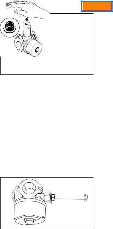
Main Menu
Primer Bulb
To install, start the retainer and bulb into the casting with the retainer tabs pointed out. Firmly push the bulb and retainer into position using a 3/4'’ (19.05 mm) deep well socket (diag. 55).
Final Checks
Before reinstalling a newly overhauled carburetor, pre-set the main mixture adjustment screw, the idle mixture adjustment screw and the idle speed adjustment screw. See “Pre-sets and Adjustments” in this chapter.
55
STANDARD SERVICE CARBURETORS
Tecumseh supplies some replacement carburetors on which parts from the old carburetors can be reused or new parts added. This Standard Service Carburetor helps to reduce dealer inventories.
Standard Service Carburetors are built in both float and diaphragm versions.
The parts from the original carburetor that are necessary to make a standard service carburetor are: choke shaft, shutter and spring, throttle lever and spring, fuel fitting, idle adjustment screw and spring. If any or all of these old parts are worn or damaged, replace each part with a new service part to assure proper function and prevent engine damage. Use the diagrams on the next page as a guide to facilitate the correct installation of parts (diag. 57 & 58).
Fuel Fitting
NOTE: MOST SERVICE CARBURETORS ARE MARKED “SVC CARB NF” IN THE PRICE LIST. THIS MEANS THAT THE CARBURETOR COMES WITH NO FUEL FITTING.
Use the parts manual to obtain the same fuel inlet fitting that was installed in the original carburetor. Install the fuel fitting in the new carburetor body in the same position as on the original carburetor. Support the carburetor body with a wood block to avoid damage to other parts. Use a bench vise or press to install the fitting squarely. Press it in until it bottoms out.
NOTE: PRESS FUEL FITTING IN SQUARELY USING CAUTION SO THAT THE CARBURETOR BODY IS NOT DAMAGED.
Inlet Fuel Fitting
To remove a leaking or damaged fuel inlet fitting, use a 1/4"(6 mm) bolt, 1/4" (6 mm) nut and 1/4" (6 mm) washer, along with a 1/2" (12 mm) nut. Use a pliers or vise to remove the plastic part of the inlet fitting. Tap the inside of the remaining metal portion of the fitting using a 1/4"- 20 (6 mm) tap. Place a 1/2" (12 mm) nut over the fuel fitting (it may be necessary to guide one side of the nut to seat it squarely to the carburetor). Next thread the 1/4" (6 mm) nut on the bolt until it contacts the shank, add the washer, and thread the bolt into the fitting until snug. Tighten the 1/4"- 20 (6 mm) nut until the fitting is removed. (diag. 56)
56 |
Choke Shaft
NOTE: Never reuse choke or throttle shutter screws, always replace with new Tecumseh service screws.
Remove the choke shutter screw from the original carburetor and remove the choke shaft. Observe the position of the ends of the choke return spring if one is present. Also observe the position of the cut-out and/or holes in choke shutter. Some chokes turn clockwise and some turn counterclockwise, note the position of the choke shaft prior to removal from the old carburetor.
If a choke stop spring is present on the new carburetor and is not used on the old carburetor, cut it off with a side cutter or pull it out using a pliers.
Test the action of choke shaft to make sure it moves freely and easily and does not bind in either open or closed position. If binding occurs, loosen the shutter screw; reposition the shutter and tighten the screw.
24
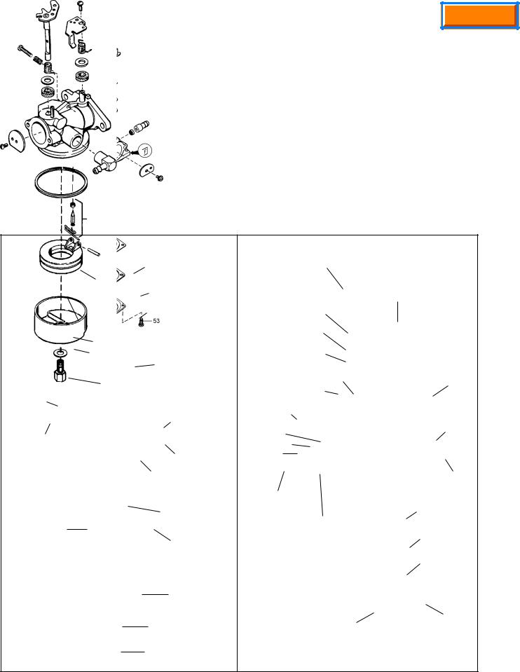
Main Menu
Throttle Lever
Remove the throttle lever and spring and file off the peened end of the throttle shaft until the lever can be removed. Install the throttle spring and lever on the new carburetor with the self-tapping screw furnished. If dust seals are furnished, install them under the return spring.
Idle Speed Adjustment Screw
Remove the screw assembly from the original carburetor and install it in the new carburetor.Turn it in until it contacts the throttle lever. Then an additional 1-1/2 turns for a static setting.
Final Checks
Consult the service section under “Pre-sets and Adjustments” and follow the adjustment procedures before placing the carburetor on the engine.
FLOAT TYPE CARBURETOR
CHOKE SHAFT
IDLE CRACK
SCREW AND
SPRING
SPRING
WASHER
FELT SEAL
CHOKE STOP
SPRING
SHUTTER
SCREW
FLOAT
SELF TAPPING SCREW
LEVER
SPRING
 WASHER
 FELT SEAL THROTTLE SHAFT
SHANK
FUEL FITTING "O" RING
SEAT AND CLIP
INLET NEEDLE
SPRING CLIP
FLOAT SHAFT
FLOAT BOWL
BOWL NUT WASHER HIGH SPEED BOWL NUT
57
DIAPHRAGM TYPE CARBURETOR
THROTTLE LEVER
AND SHAFT
|
CHOKE LEVER |
||||
|
AND SHAFT |
||||
SPRING |
|
|
|
|
|
WASHER |
|
|
|
|
|
FELT SEAL |
|
|
|
|
|
THROTTLE SHUTTER |
|
FUEL INLET |
|||
SHUTTER SCREW |
|
||||
|
|
|
|
||
IDLE |
|
|
|
|
|
ADJUSTMENT |
|
|
|
|
|
SCREW |
|
|
CHOKE |
||
SEAL |
|
|
SHUTTER |
||
|
|
|
|
||
WASHER |
|
|
|
|
|
SPRING |
|
|
|
|
|
|
|
|
SHUTTER |
||
|
|
|
SCREW |
||
LOW SPEED |
|
|
|
|
|
ADJUSTMENT |
|
|
|
|
|
SCREW |
DIAPHRAGM |
||||
HIGH SPEED |
|
|
|
|
|
ADJUSTMENT |
DIAPHRAGM |
||||
SCREW |
|||||
|
GASKET |
||||
|
|
||||
|
DIAPHRAGM |
||||
|
|
COVER |
|||
|
|
|
|
|
|
|
|
|
|
|
|
|
|
|
|
|
|
|
|
|
|
|
|
PRIMER FITTING |
DIAPHRAGM |
|
COVER SCREW |
||
|
58
25
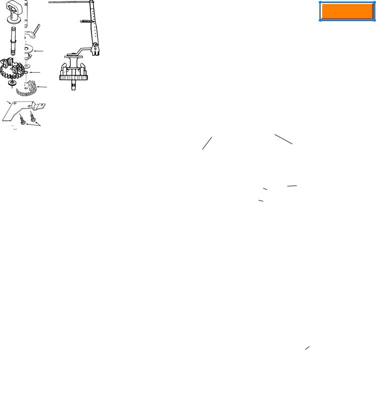
Main Menu
CHAPTER 4 GOVERNORS AND LINKAGE
GENERAL INFORMATION
This chapter includes governor assembly and linkage illustrations to aid in governor or speed control assembly.
Tecumseh 4 cycle engines are equipped with mechanical type governors. The governor’s function is to maintain a constant R.P.M. setting when engine loads are added or taken away. Mechanical type governors are driven off the engine’s camshaft gear. Changes in engine R.P.M. cause the governor to move the solid link that is connected from the governor lever to the throttle in the carburetor. The throttle is opened when the engine R.P.M. drops and closes as the engine load is removed.
OPERATION |
|
|
|
|
|
|
|
SPRING |
|
|
|
|
|
|
|
||||
|
|
|
|
|
|
|
|
|
|
|
|
|
|
|
|||||
As the speed of the engine increases, the governor |
|
|
|
|
|
|
|
|
|
|
|
|
|
|
|
||||
weights (on the governor gear) move outward by |
|
THROTTLE |
|
GOVERNOR SHAFT |
|
|
|
|
|
|
|
||||||||
centrifugal force.The shape of the governor weights force |
|
|
|
|
|
|
|
|
|
||||||||||
|
|
|
|
|
|
|
|
|
|
||||||||||
|
|
|
|
|
|
|
|
|
|
|
|
|
|
|
|||||
the governor spool to lift. The governor rod maintains |
|
|
|
|
|
|
|
|
|
|
|
|
|
|
|
||||
contact with the governor spool due to the governor spring |
|
|
|
|
|
|
|
|
|
|
|
|
|
|
|
||||
tension. As the spool rises, the governor rod rotates, |
|
|
|
WEIGHTS |
|
|
|
|
GOVERNOR |
|
|||||||||
causing the attached outer governor lever to pull the solid |
|
|
|
|
|
|
|
|
|||||||||||
|
|
|
|
|
|
|
|
|
SPOOL |
|
|||||||||
link and close the throttle opening. When the engine |
|
|
|
|
|
|
|
|
|
|
|||||||||
|
|
GOVERNOR GEAR |
|
|
|
|
|
|
|
|
|
|
|
||||||
speed decreases, the lower centrifugal force allows the |
|
|
|
|
|
|
|
|
|
|
|
|
|
||||||
|
|
|
|
|
|
|
|
|
|
|
|
|
|
|
|||||
governor weights to be pulled in by the governor spring. |
|
|
|
|
|
|
|
|
|
|
|
|
|
|
1 |
||||
As the spool lowers, the governor rod rotates and the |
|
|
|
|
|
|
|
|
|
|
|
|
|
|
|||||
|
|
|
|
|
|
|
|
|
|
|
|
|
|
|
|||||
|
|
|
|
|
|
|
|
|
|
|
|
|
|
|
|||||
solid link pushes the throttle to a more open position (diag. |
|
|
|
|
|
|
|
|
|
|
|
|
|
|
|
||||
1). |
|
|
|
|
|
|
|
|
|
|
|
|
|
|
|
|
|
|
|
INTERNAL COMPONENTS (VARIOUS STYLES) |
|
|
|
|
|
|
|
|
|
|
|
|
|
||||||
|
|
|
|
|
|
|
|
|
|
|
|
|
|
|
|
|
|
|
|
RETAINING |
|
|
|
|
RETAINING |
|
|
|
|
|
|
|
|
|
|
|
|
|
|
RING |
|
|
|
|
RING |
|
|
|
|
|
|
|
|
|
|
|
|
|
|
SPOOL |
|
|
|
|
SPOOL |
|
|
|
|
|
|
|
|
|
|
|
|
|
|
|
|
|
|
|
|
|
|
|
|
|
|
|
|
|
|
|
|
||
RETAINING |
|
|
SPOOL |
|
WASHER |
|
|
|
|
|
|
|
|
|
|
|
SPOOL |
|
|
|
|
UPSET |
|
|
|
|
|
|
|
|
|
|
|
|
|
||||
RING |
|
|
|
|
|
|
|
|
|
|
|
|
|
|
|
|
|||
|
|
|
NO RETAINING |
|
RETAINING |
|
SPOOL |
|
|
|
|
|
|
|
|
|
|||
GEAR ASSY. |
|
|
RING |
|
|
RING |
|
|
|
|
|
|
|
|
|
||||
|
|
SHAFT |
|
|
GEAR ASSY. |
|
|
|
|
|
|
|
|
|
|
|
|
|
|
(GOV.) |
|
|
|
|
WASHER |
|
|
|
|
|
|
|
|
|
|
|
|
||
|
|
|
|
|
(GOV.) |
|
|
|
|
|
|
|
|
|
SHAFT |
|
|||
|
|
|
|
|
|
RETAINING |
|
|
|
|
|
|
|
||||||
|
|
|
|
|
|
|
|
|
|
|
|
|
|
|
|||||
|
|
|
|
|
WASHER |
|
RING |
|
|
|
|
|
|
|
|
||||
WASHER |
|
|
|
|
|
|
|
|
|
|
|
|
|
|
|
|
|
||
|
|
GEAR ASSY. |
|
SPACER |
|
|
GEAR |
|
|
|
|
|
|
GEAR ASSY. |
|||||
|
|
|
|
|
|
|
|
|
|
|
|
||||||||
|
|
|
(GOV.) |
|
|
|
|
|
|
|
|
(GOV.) |
|
||||||
|
|
|
|
|
|
|
|
ASSY. |
|
|
|
|
|
|
|
||||
|
|
|
|
|
|
|
|
|
|
|
|
|
|
|
|
|
|||
|
|
|
WASHER |
|
|
|
BRACKET |
|
(GOV) |
|
|
|
|
|
|
|
|
||
SHAFT |
|
|
|
|
|
|
|
|
|
|
|
|
|
|
WASHER |
|
|||
|
|
|
|
SHAFT |
|
|
|
|
|
|
|
|
|
|
|||||
|
|
|
|
|
|
|
|
|
|
|
|
|
|
||||||
|
|
|
|
|
|
|
|
|
|
|
|
|
|
|
|
|
|
||
|
|
|
|
|
|
|
|
SCREWS |
|
|
|
|
|
|
|
|
|||
TVS STANDARD 2 |
|
TVS UPSET 3 |
MEDIUM FRAME 4 |
HORIZONTAL |
5 |
|
|
|
|
LEV |
6 |
||||||||
TROUBLESHOOTING
Engine problems where the governor is suspected to be the cause, may actually be the result of other engine system problems. Hunting (engine R.P.M. surging up and down) indicates that the engine is incapable of maintaining a constant R.P.M. with or without an engine load. Engine overspeeding (either with or without throttle movement) must be corrected immediately before serious engine damage occurs. Use the following procedure to diagnose a suspected governor problems.
26
 Loading...