


Tecumseh HXL, AV600, TCH200, AV520, HSK Manual
...Tecumseh
Quick Reference
Service Information
Covers Engine and Transmission Product
Form No.695933 R 7/00

Introduction
This booklet contains the quick reference and basic troubleshooting information previously found on Tecumseh wall charts and in the Technician's Handbooks.
This booklet is designed to be used as a work bench quick reference guide when servicing Tecumseh engines and motion drive systems.
Technician's Note:
Tecumseh engines are manufactured to meet EPA and CARB standards. As a technician, it is unlawful to re-calibrate or replace a fuel nozzle or jet (bowl nut) with a part from any other carburetor that was not originally designed for that engine. All speed adjustments must remain within the limits that are specified for each engine and are not to exceed the maximum. This can only be deviated from if specifically approved by Tecumseh Products, EPA and CARB.
1

Note: Torque specifications listed should not be confused with the torque value observed on engines which have been run.
The Torque specifications take relaxation into account so sufficient clamping force exists after an engine has reached operating temperature.
Torques listed are intended to cover highly critical areas. More extensive torques are found in the respective repair manual.
Torque Specifications
TWO-CYCLE ENGINE SERIES
840 - 850 TWO-CYCLE ENGINE SERIES
Location |
Inch lbs. Torque |
Nm |
Engine Designation |
|||||||||||
|
|
|
|
TVS |
|
|
TVXL |
|
|
HSK |
|
HXL |
|
|
|
|
|
|
|
|
|
|
|
||||||
|
|
|
|
|
|
|
|
|
|
|
|
|
|
|
Crankcase to Cylinder |
120-204 |
13.5-23 |
|
• |
|
|
• |
|
|
• |
|
• |
||
Flywheel Nut |
360-420 |
41-47.5 |
|
• |
|
|
• |
|
|
• |
|
• |
|
|
Adapter Plate to Cylinder |
160-220 |
18-25 |
|
• |
|
|
• |
|
|
|
|
|
|
|
TC TWO-CYCLE ENGINE SERIES |
|
|
|
|
|
|
|
|
|
|
|
|
|
|
Location |
Inch lbs. Torque |
Nm |
Engine Designation |
|||||||||||
|
|
|
|
TC200 |
|
|
TC300 |
|
|
TCH200/ |
300 |
|
|
|
|
|
|
|
|
|
|
|
|
|
|||||
|
|
|
|
|
|
|
|
|
|
|
|
|
|
|
Cylinder to Crankcase |
80-95 |
9-11 |
|
• |
|
|
• |
|
|
• |
|
|
|
|
Crankcase Cover to Crankcase |
70-100 |
8-11 |
|
• |
|
|
• |
|
|
• |
|
|
|
|
Flywheel Nut |
190-250 |
21.5-28.5 |
|
• |
|
|
• |
|
|
• |
|
|
|
|
|
|
|
|
|
|
|
|
|
|
|
|
|
|
|
TWO-CYCLE ENGINE SERIES (AV520/600, TVS600, AH520, AH/HSK600)
Location |
Inch lbs. Torque |
Nm |
Engine Designation |
||||||||
|
|
|
|
AV520/600 |
|
TVS600 |
|
AH/HSK600 |
|
AH520 |
|
|
|
|
|
|
|
|
|
||||
|
|
|
|
|
|
|
|
|
|
|
|
Connecting Rod |
40-50 |
4.5-5.5 |
|
• |
|
• |
|
• |
|
• |
|
Housing Base to Cylinder |
80-120 |
9-13.5 |
|
• |
|
• |
|
• |
|
• |
|
Cylinder Head to Cylinder |
100-140 |
11-16 |
|
• |
|
• |
|
• |
|
• |
|
Flywheel Nut AV Industrial (Point Ignition) |
216-300 |
24.5-34 |
|
• |
|
|
|
|
|
• |
|
(670 Series AV 520 and All AV 600) |
|
|
|
|
|
|
|
|
|
|
|
Flywheel Nut (C.D. Ignition) |
264-324 |
30-36.5 |
|
• |
|
• |
|
• |
|
• |
|
|
|
|
|
|
|
|
|
|
|
|
|
2

Two Cycle Troubleshooting
As an aid in troubleshooting any piece of equipment, interview the customer, and review conditions and symptoms of the problem. Examine exterior for clues: leaks, excessive dirt, damaged or new parts.
|
FUEL SYSTEM |
|||
|
|
Engine Will |
||
|
|
Not Start |
||
|
|
|
|
|
|
|
|
|
|
|
|
Check if spark |
||
|
|
plug is wet or dry |
||
|
Wet |
|
Dry |
|
|
|
|
|
|
|
|
|
|
|
Defective |
|
Review with customer |
||
spark plug |
|
priming or choking |
||
|
|
|
procedure |
|
|
|
|
||
|
|
|
(3-5 primes, if |
|
Restricted |
|
equipped, waiting 2 |
||
|
seconds between |
|||
air filter |
|
|||
|
each prime) |
|||
|
|
|
||
|
|
|
|
|
|
|
|
|
|
|
|
|
Carburetion problem* |
|
Improper fuel mix |
|
|||
or stale fuel |
|
(bad bowl gasket) |
||
|
|
|
||
|
|
|
|
|
|
|
|
Check fuel supply |
|
Exhaust ports |
|
|||
|
and fuel cap vent |
|||
plugged |
|
|||
|
|
|
||
|
|
|
|
|
|
|
|
|
|
Carburetion |
|
Restriction in |
||
problems due to |
|
fuel system (filter, |
||
flooding, over |
|
screen) |
||
priming, etc.* |
|
|
|
|
|
|
|
||
|
|
|
|
|
|
|
|
Poor |
|
Ignition System |
|
compression |
||
|
|
|
|
|
|
|
|
|
|
|
|
|
Damaged reed, port |
|
Crankcase seals |
|
|||
|
plugs, seals or |
|||
or gaskets leaking |
|
gaskets |
||
NOTE: Refer to Technician's Handbook for a more detailed list of remedies.
*Carburetor Troubleshooting use Technician's Handbook or Carburetor Troubleshooting Booklet, Form No. 695907. Video No. 695015.
(CONTINUED ON NEXT PAGE) |
3 |

Two Cycle Troubleshooting - continued
IGNITION SYSTEM
Engine Will
Not Start
Check for spark
Spark |
No Spark |
|
|
|
|
|
|
Check flywheel for
correct key, damaged Replace spark plug key or key adaptor
Set proper air gap on |
|
Isolate engine from all |
||
external coil |
|
equipment (disconnect |
||
|
|
|
wiring harness), repeat |
|
|
|
|
test |
|
Set proper point gap, |
Spark |
|
No Spark |
|
check condensor and |
|
|||
timing (if equipped) |
|
|
|
|
|
|
Equipment problem, |
||
|
|
|||
|
|
check switches, wiring |
||
Test coil for |
||||
and equipment |
||||
intermittent or weak |
controls |
|||
spark |
|
|
||
|
|
|||
|
|
|
|
|
|
|
|
|
|
|
|
Parasitic load too high |
||
Check electric starter |
||||
|
|
|||
if applicable |
|
|
||
Engine problem, check for shorts or grounds in wiring
Test ignition module
NOTE: Refer to Technician's Handbook for a more detailed list of remedies.
4

Note: Torque specifications listed should not be confused with the torque value observed on engines which have been run.
The Torque specifications take relaxation into account so sufficient clamping force exists after an engine has reached operating temperature.
Torques listed are intended to cover highly critical areas. More extensive torques are found in the respective repair manual.
Torque Specifications
FOUR-CYCLE LIGHT FRAME ENGINE SERIES
(TVS, TNT, ECV, LAV, LEV, H, HS, OHH, OVRM and VLV)
Location |
Inch lbs. Torque |
Nm |
|
|
Engine Designation |
|
|
|
|
|
|||||||||||
|
|
|
TVS |
|
TNT |
|
ECV |
|
LAV |
|
H/HSK |
|
HS/HSSK |
|
OVRM |
|
VLV |
|
LEV |
|
OHH |
|
|
|
|
|
|
|
|
|
|
|
|
||||||||||
Rocker Arm Stud Lock Nut |
100-140 |
11-16 |
|
|
|
|
|
|
|
|
|
|
|
|
• |
|
|
|
|
|
• |
Connecting Rod |
95-110 |
11-12.5 |
• |
|
• |
|
• |
|
• |
|
• |
|
• |
|
• |
|
• |
|
• |
|
• |
|
|
|
|
|
|
|
|
|
|
|
|
|
|
|
|
|
|
|
|
|
|
Cylinder Head |
160-210 |
18-24 |
• |
|
• |
|
• |
|
• |
|
|
|
|
|
• |
|
|
|
|
|
|
Cylinder Head |
220-240 |
25-27 |
|
|
|
|
|
|
|
|
|
|
|
|
• |
|
|
|
|
|
• |
Cylinder Head |
180-220 |
20.5-25 |
|
|
|
|
|
|
|
|
|
|
|
|
|
|
• |
|
|
|
|
Mounting Flange or Cylinder Cover |
100-130 |
11-14.5 |
• |
|
• |
|
• |
|
• |
|
• |
|
• |
|
• |
|
• |
|
• |
|
• |
Flywheel Nut (Cast Iron) |
500-600 |
42-50 |
• |
|
• |
|
• |
|
• |
|
• |
|
• |
|
• |
|
• |
|
• |
|
• |
Flywheel Nut (Aluminum) |
400-500 |
45-56.5 |
• |
|
• |
|
• |
|
• |
|
• |
|
• |
|
• |
|
• |
|
• |
|
• |
|
|
|
|
|
|
|
|
|
|
|
|
|
|
|
|
|
|
|
|
|
|
FOUR-CYCLE MEDIUM FRAME ENGINE SERIES
(TVM, TVXL, H, V, HM, OVM, OVXL, OHM, OHSK and OHV)
Location |
Inch lbs. Nm |
|
Torque |
Connecting Rod |
160-180 |
18-20.5 |
Connecting Rod |
200-220 |
22.5-25 |
Connecting Rod |
200-240 |
22.5-27 |
Cylinder Head Bolts |
220-240 |
25-27 |
Cylinder Head Bolts |
180-240 |
20.5-27 |
Cylinder Head Bolts |
160-210 |
18-24 |
Rocker Adj. Lock Screw |
65-80 |
7-9 |
Rocker Arm Stud Lock Nut |
110-130 |
12.5-14.5 |
Rocker Arm Hex Jam Nut |
15-20 |
2 |
Rocker Arm Studs |
170-210 |
19-24 |
Rocker Arm Box to Head |
75-130 |
8.5-14.5 |
Rocker Box Cover |
15-20 |
2 |
Rocker Box Cover (Four Screw) |
40-65 |
4.5-7 |
Mounting Flange or Cylinder Cover 100-130 |
11-14.5 |
|
Mounting Flange or Cylinder Cover 110-140 |
12.5-16 |
|
Flywheel Nut |
400-550 |
45-62 |
Flywheel Nut (External Ignition) |
600-800 |
68-90 |
|
|
|
Engine Designation
TVM125, 140 |
H50-60 |
V70 |
H70 |
TVM & TVXL 170-195-220 |
HM/HMSK70-100 |
OVM/OVXL, OHV120-125 |
OHSK80-130 OHM120 |
OHV11-13,OHV110- 135, 206 Series OHV135-145 203 Series OHV15-17.5 204 Series |
••
|
|
• |
• |
• |
• |
• |
• |
|
• |
|
|
|
|
|
|
|
|
|
|
||
|
|
|
|
|
|
• |
• |
• |
• |
|
• |
• |
• |
• |
• |
• |
|
|
|||
|
|
|
• |
|||||||
|
|
|
|
|
|
|
|
• |
||
|
|
|
|
|
|
• |
• |
|
||
|
|
|
|
|
|
|
|
|||
|
|
|
|
|
|
• |
• |
|
• |
|
|
|
|
|
|
|
• |
• |
|
|
|
|
|
|
|
|
|
• |
• |
|
|
|
• |
• |
• |
• |
|
|
|
• |
• |
• |
|
• |
• |
• |
• |
• |
• |
|||||
• |
• |
• |
• |
|||||||
• |
• |
• |
• |
• |
• |
|||||
|
|
|
|
5

Torque Specifications - continued
FOUR-CYCLE LARGE FRAME ENGINE SERIES (CAST IRON BLOCK HH, VH and OH)
Location |
Inch lbs. |
Nm |
Engine Designation |
|||||
|
Torque |
|
|
|
|
|
|
|
|
|
|
HH |
|
VH |
|
OH |
|
|
|
|
|
|
||||
|
|
|
|
|
|
|
|
|
Connecting Rod |
86-110 |
10-12.5 |
• |
|
• |
|
• |
|
Cylinder Head |
180-240 |
20.5-27 |
• |
|
• |
|
• |
|
|
|
|
|
|
|
|
|
|
Mounting Flange & Cylinder Cover |
100-130 |
11-14.5 |
• |
|
• |
|
• |
|
Rocker Arm Shaft to Box |
180-220 |
20.5-25 |
|
|
|
|
• |
|
|
|
|
|
|
|
|
|
|
Rocker Arm Box to Cylinder Head |
80-90 |
9-10 |
|
|
|
|
• |
|
Flywheel Nut |
600-660 |
68-74.5 |
• |
|
• |
|
• |
|
|
|
|
|
|
|
|
|
|
FOUR-CYCLE HEAVY FRAME ENGINE SERIES (V-TWIN) |
|
|
|
|||
|
Location |
Inch lbs. |
Nm |
Engine Designation |
|
|
|
|
Torque |
|
|
|
|
|
|
|
|
|
|
|
|
|
|
|
TVT |
|
|
|
|
|
|
|
|
|
|
Connecting Rod |
200-220 22.5-25 |
• |
|
|
|
|
Cylinder Head Bolts |
220-240 25-27 |
• |
|
|
|
|
|
|
|
|
|
|
|
Rocker Arm Jam Nut |
110-130 12.5-14.5 |
• |
|
|
|
|
Rocker Arm Cover Mounting Screw |
52 |
6 |
• |
|
|
|
|
|
|
|
|
|
|
Mounting Flange/Cylinder Cover |
240-260 27-29 |
• |
|
|
|
|
Flywheel Nut |
600-800 |
68-90 |
• |
|
|
|
|
|
|
|
|
|
6

Four Cycle Troubleshooting
As an aid in troubleshooting any piece of equipment, interview the customer, and review conditions and symptoms of problem. Examine exterior for clues: leaks, excessive dirt, damaged or new parts.
|
|
FUEL SYSTEM |
||
|
|
Engine Will |
||
|
|
Not Start |
||
|
|
|
|
|
|
|
|
|
|
|
|
Check if spark plug is |
||
|
|
wet or dry |
||
|
Wet |
|
Dry |
|
|
||||
|
|
|
|
|
Defective |
|
Review with the |
||
spark plug |
|
customer proper |
||
|
|
|
priming procedure |
|
|
|
|
||
|
|
|
(3-5 primes, waiting |
|
Restricted air filter |
|
2 seconds between |
||
|
each prime) |
|||
|
|
|
||
|
|
|
|
|
|
|
|
|
|
|
|
|
|
|
|
|
|
If equipped with a |
|
|
|
|
||
Improper or |
|
choke, check for full |
||
stale fuel |
|
travel. Check throttle |
||
|
cable and control for |
|||
|
|
|
||
|
|
|
proper adjustment. |
|
|
|
|
|
|
Carburetion problems |
|
|
|
|
|
Check fuel supply and |
|||
due to flooding, over |
|
|||
priming, etc.* |
|
fuel cap vent |
||
|
|
|
|
|
|
|
|
|
|
|
|
|
Restriction in fuel |
|
|
|
|
||
Ignition system |
|
system (filter) |
||
|
|
|
||
|
|
|
|
|
|
|
|
|
|
|
|
|
Carburetion problem* |
|
|
|
|
(bad bowl gasket) |
|
|
|
|
|
|
|
|
|
|
|
|
|
|
Poor |
|
|
|
|
compression |
|
NOTE: Refer to Technician's Handbook for a more detailed list of remedies.
*Carburetor Troubleshooting, use Technician's Handbook or Carburetor Troubleshooting Booklet, Form No. 695907. Video No. 695015.
7

Four Cycle Troubleshooting - continued
|
IGNITION SYSTEM |
|
|
Engine Will |
|
|
Not Start |
|
|
|
|
|
|
|
|
Check for |
|
|
spark |
|
Spark |
|
No Spark |
|
||
|
|
|
Check flywheel for correct key, damaged or sheared key
Set proper air gap on external coil
Set proper point gap, check condensor and timing
Test coil for intermittent or weak spark
|
Replace spark plug |
|
|
|
|
|
|
|
|
Isolate engine from all |
|
|
equipment (disconnect |
|
|
wiring harness), repeat |
|
|
test |
|
Spark |
|
No Spark |
|
|
|
Equipment problem, |
Engine problem, |
|
check switches, |
||
check for shorts or |
||
wiring and |
||
grounds in wiring |
||
equipment controls |
||
|
Parasitic load too |
Test ignition |
high |
module |
NOTE: Refer to Technician's Handbook for a more detailed list of remedies.
8
Tecumseh 2 Cycle Diaphragm Adjustments
NOTE: For meeting emission requirements, some carburetors have fixed-main or idle jets. The absence of the adjustment screw indicates fixed jets and no adjustment is necessary.
Diaphragm-Dual Adjustment.
Turn mixture adjusting screws in finger tight to the closed position, then one (1) turn out from closed position. This setting is approximate. This will allow the engine to be started so the carburetor can be fine tuned.
Start the engine and let it warm up for approximately 3-5 minutes. Do not adjust the carburetor when the engine is cold.
Set the throttle control to idle. If it is a fixed speed type, manually hold the throttle against the idle speed adjustment screw.
IDLE MIXTURE
SCREW
MAIN MIXTURE SCREW
NOTE: If no tension spring is present, it may be a fixed jet.
1
The throttle lever must be held against the crack screw for low speed adjustments or all adjustments will be incorrect and cause poor performance and unsatisfactory operation.
With the engine idling and throttle lever against the idle speed regulating screw, turn the low speed adjustment screw slowly clockwise from the NORMAL setting until the engine falters. Remember this location. Turn the screw counterclockwise until engine just starts to sputter or drops in R.P.M.. Remember this location. Turn the screw clockwise until it is halfway between your first position where the engine faltered and your last position where the engine started to sputter. This will be the optimum low speed setting on your carburetor.
Next run the engine at governed speed. The high speed adjustments are made basically the same as the low speed adjustments, with the exception of the settings being made 1/8 of a turn at a time, from the NORMAL settings. NOTE: It may be necessary to re-check the idle mixture adjustment after performing the high speed adjustment.
Diaphragm-Single Adjustment.
Turn the mixture adjustment screw finger tight to the closed position, then one (1) turn out from the closed position. This setting is approximate and will allow the engine to be started so the carburetor can be finetuned.
Start the engine and let it warm up for approximately 3-5 minutes. Do not adjust the carburetor when the engine is cold.
Set the throttle control to idle. If it is a fixed speed type, manually hold the throttle against the idle speed adjustment screw.
NOTE: If the engine falters or stops after the choke lever is moved to the "OFF" position, open the mixture adjusting screw 1/4 turn (counterclockwise) and restart the engine.
With the engine running, place the speed control in the "slow" position to make mixture adjustments. Turn the mixture screw slowly clockwise from the NORMAL setting until the engine falters. Remember this location. Turn the screw counterclockwise until the engine just starts to sputter or drops in R.P.M. Remember this location. Turn the screw clockwise until it is halfway between your first position where the engine faltered and your last position where the engine started to sputter. This will be the optimum setting on your carburetor.
9
TC Series Governor Adjustment
Three different styles of governor systems are used on TC engines. Use the following illustrations (diags. 2 and 3) to identify the governor system used and the following procedure to adjust the governed engine speed.
1.Allow the engine to run for at least 5 minutes to reach operating temperature. Make sure the air filter (if equipped) is clean and the choke is in the off position.
2.Using a Vibratach (part# 670156) or other tachometer, determine the engine's R.P.M. at idle and wide open throttle. Refer to Microfiche card 30, or a computer parts look-up program to obtain the recommended engine speeds.
3.Using the applicable illustration, either bend the speed adjusting lever toward the spark plug end of the engine to decrease high speed R.P.M., or bend the lever in the opposite direction to increase R.P.M. On TC Type II engines, turn the speed adjusting screw out to increase or in to decrease engine high speed R.P.M. If the speed adjustment screw is turned out to increase the engine R.P.M., the speed control lever must be moved to allow the speed control plunger to contact the speed adjustment screw.
4.The low speed is set by moving the throttle control to the lowest speed position and adjusting the low speed adjustment screw on the carburetor.
HOOK |
TYPE I |
|
|
|
(style 1) |
SPEED
ADJUSTING
LEVER
 TO INCREASE SPEED
 TO DECREASE SPEED
TYPE I
(style 2)
HOOK SPRING ON
NOTCH  SPEED ADJUSTING LEVER
2
1.AIR VANE
2.BACKLASH SPRING
3.GOVERNOR LINK
4.GOVERNOR SPRING
5.MOUNTING SCREW
6.SPEED ADJUSTMENT SCREW
7.SPEED CONTROL BODY
8.SPEED CONTROL LEVER
9.SPEED CONTROL PLUNGER
Spring Color |
Spring Position |
|
|
Orange or Green |
1 |
|
|
Pink, Red, or Black |
2 |
|
|
|
SPRING |
HOOK |
|
POSITION 1 |
SPRING ON |
TYPE II: |
1 |
NOTCH |
|
||
(style 3) |
|
POSITION 2 |
|
|
|
9 |
|
|
HIGH SPEED |
|
4 |
GOVERNOR |
|
ADJUSTMENT |
||
|
7 |
|
INSERT THROTTLE |
|
LINK AND SPRING |
|
|
|
|
|
|
HERE |
|
|
OUT TO INCREASE |
|
6 |
IN TO DECREASE |
|
|
3
10
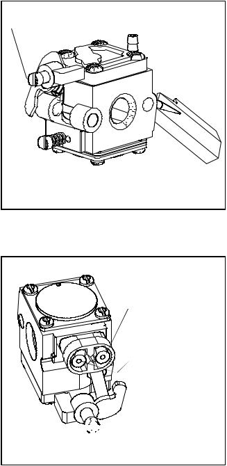
Walbro (WTA, WT) and Tillotson (HU) Diaphragm Adjustment
Carburetor Pre-Set and Adjustment
Both the Walbro and the Tillotson carburetors used on TC engines have non-adjustable main mixture jets. Only the idle mixture is adjustable by turning the idle mixture screw. Use the following procedure to pre-set the idle mixture screw. Turn the idle mixture screw (clockwise) finger tight to the closed position, then turn the screw counterclockwise to obtain the proper preset (diag. 4).
Walbro Model WTA, WT 1 - 1-1/8 turns Tillotson Model HU 1-1/4 - 1-3/8 turns
Final Idle Mixture Adjustment
Start the engine and allow it to reach normal operating temperature (after 3-5 minutes). As the speed control is set at the idle position, turn the idle mixture screw slowly clockwise until the engine R.P.M. just starts to decrease. Stop and note this screw position. Turn the idle mixture screw slowly counterclockwise, the engine will increase in R.P.M. Continue to slowly turn the screw until the engine R.P.M. starts to decrease. Note this position and turn the mixture screw back clockwise halfway between the two engine R.P.M. drop off positions. The idle mixture adjustment is complete.
Some carburetors came equipped with a main mixture adjusting screw. To adjust the main mixture, follow the steps for idle adjustment.
Emissionized Tillotson
Similar in design and operation, the Tillotson emission carburetor uses a fixed main jet with an adjustable idle. The idle circuit has a limiter cap to prevent over richening. The cap is locked onto the adjustment screw in a rich position, allowing only a leaner adjustment. The main is fixed on these, which means that the main mixture limiter is non-functional on Tecumseh built engines (diag. 4a).
In compliance with E.P.A. and C.A.R.B. regulations the following procedure must be followed.
NOTE: These caps can be removed for servicing of the carburetor. Follow these steps.
1.Turn the caps clockwise until they hit the stops.
2.Remove the caps with a pointed instrument such as an awl.
3.Then turn the screws in until softly seated, note thenumberofturns. Thescrewsmustbereinstalled to this same static setting. Replacement of the caps is required to maintain E.P.A. and C.A.R.B. emission compliance.
IDLE SPEED ADJUSTMENT |
SCREW |
IDLE MIXTURE |
SCREW |
4 |
IDLE MIXTURE
LIMIT SCREW
FIXED MAIN
(MIXTURE SCREW NOT FUNCTIONAL ON MOST TECUMSEH BUILT ENGINES)


 IDLE SPEED ADJUSTMENT
SCREW
4a
11

2-Cycle Engine Speed and Mixture Adjustments: TVS/TVXL840
IDLE SPEED
ADJUSTMENT
HIGH SPEED |
|
|
|
ADJUSTMENT |
|
|
|
5 |
HOLDING |
STATIC GOVERNOR |
6 |
SCREW |
ADJUSTMENT SCREW |
||
Linkage Location |
Static Governor Adjustment |
|
|
To aid in the proper reassembly of the governor linkage, mark the linkage locations.
To adjust the static governor, loosen the holding screw, rotate the governor arm and slotted shaft in the direction that will open the throttle to the wide open position, and then re-tighten the holding screw.
HSK/HXL840-850
IDLE RPM |
HIGH SPEED |
ADJUSTMENT |
RPM |
SCREW |
ADJUSTMENT |
|
SCREW |
7
The HXL840 - 850 Series with variable speed control have the following adjustments. Idle speed is set at the carburetor crack screw. High speed is set with the screw shown above. Always check Microfiche card 30 or Parts Smart computer program for correct speed settings.
 INCREASE
DECREASE
BEND TAB
8
R.P.M. adjustment of fixed speed models is done by bending the tab as shown.
Governor and Linkage for Air Vane
VANE ASSEMBLY
TO ADJUST HIGH-
SPEED ROTATE
CLOCKWISE TO
INCREASE
COUNTERCLOCKWISE
TO DECREASE |
9 |
|
BEND TAB
ADJUST RPM
DECREASEINCREASE
HORIZONTAL FIXED SPEED |
10 |
PLASTIC AIR VANE GOVERNOR |
Rotate sleeve clockwise to increase R.P.M., counterclockwise to decrease R.P.M.
NOTE: The sleeve is serrated to rotate in a clockwise direction and must be raised using the sleeve tabs before it can be rotated counterclockwise.
To disassemble, remove choke shutter with needle-nose pliers; the vane assembly may then be removed from the carburetor.
12

Governors and Linkage for Air Vane - continued
ADJUST RPM BY
LOOSENING SCREW AND
SLIDING BRACKET
DECREASEINCREASE
HORIZONTAL FIXED SPEED |
11 |
(ALUMINUM AIR VANE GOVERNOR) |
ADJUST RPM BY |
SPRING |
|||
LOOSENING SCREW AND |
|
|
||
|
|
|||
SLIDING BRACKET |
|
|
||
|
|
INCREASE |
|
|
|
|
|
|
|
|
|
|
|
|
|
DECREASE |
|
|
|
GOVERNOR LINK
HORIZONTAL FIXED SPEED |
13 |
|
|
|
|
HIGH SPEED |
|
IDLE RPM |
|
|
|
RPM |
|
|
|
|
ADJUSTMENT |
||
ADJUSTMENT |
|
|
|||
|
|
|
|
||
IDLE |
|
|
|
|
|
MIXTURE |
|
HOLE NOT |
|
||
|
|
|
|
||
|
|
|
|
ON ALL |
|
|
|
|
SPRING |
|
|
|
|
VERTICAL ENGINE |
12 |
||
VARIABLE SPEED-REMOTE CONTROL |
|||||
IDLE RPM
ADJUSTMENT
HIGH SPEED
IDLE RPM ADJUSTMENT MIXTURE
THIS HOLE NOT |
|
PRESENT ON ALL |
|
MODELS |
|
SPRING |
|
VERTICAL ENGINE |
14 |
FIXED SPEED-REMOTE CONTROL |
|
|
HIGH SPEED RPM |
|
|
|
|
||
|
ADJUSTMENT |
|
|
|
|
||
IDLE RPM |
|
|
|
|
|
THIS HOLE NOT |
|
ADJUSTMENTS |
|
|
|
|
|
||
|
|
THIS HOLE NOT |
|
|
PRESENT ON ALL |
||
|
|
|
|
MODELS |
|
||
|
|
PRESENT ON |
|
|
|
||
|
|
|
|
|
|
||
|
|
ALL MODELS |
RPM ADJUSTMENT |
|
SPRING |
|
|
VERTICAL ENGINE |
|
|
SPRING |
|
|
|
|
|
|
|
|
|
|
||
|
|
|
|
|
|
||
VARIABLE SPEED |
15 |
VERTICAL ENGINE FIXED SPEED |
16 |
||||
MANUAL CONTROL |
|||||||
13
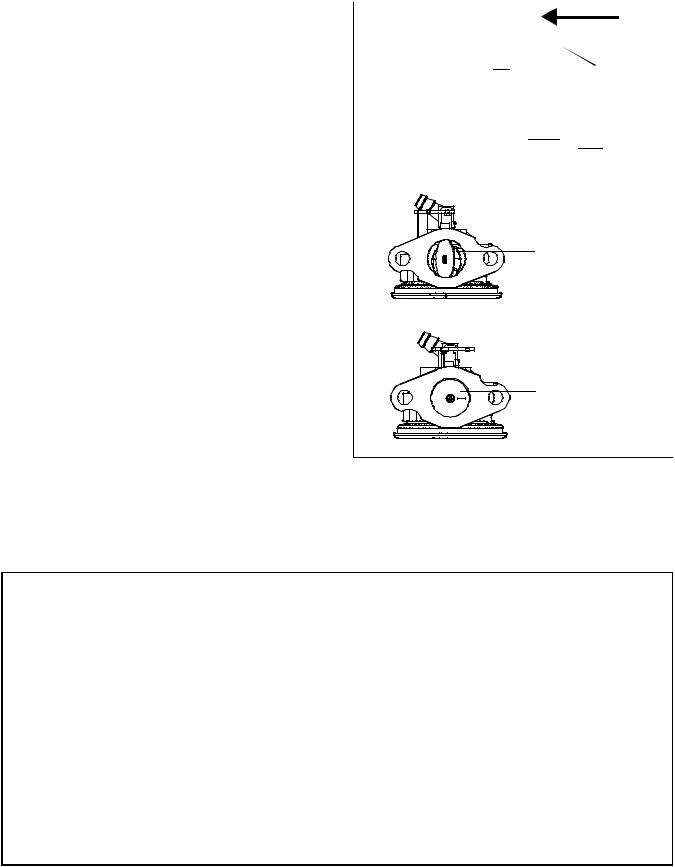
Static Governor Adjustments
The purpose of making a static governor adjustment is to remove all free-play between the governor spool and the carburetor (see illustration). Any freeplay here will result in hunting/surging or erratic running. After completing this procedure, always re-check the engine speeds using the steps outlined in the following pages.
To set the static governor, do the following:
1.Be sure the engine is stopped or damage may occur.
2.If equipped with a throttle control, place the throttle in the high speed position.
3.Loosen the governor clamp or screw.
4.Hold the governor arm and link in the W.O.T. (wide open throttle) position, then rotate the shaft or shaft/clip assembly in the same direction and tighten the screw.
5.If engine speed adjustments are needed, follow the steps described in following pages.
SPRING
CHOKE
THROTTLE
GOVERNOR
ROD
NO FREE
PLAY GOVERNOR
SPOOL
WIDE OPEN
THROTTLE
CLOSED
THROTTLE
Governor Shaft Pressed In Depth
When assembling governor shaft into a flange or cover mounting boss, refer to this chart for exposed shaft length.
Engine Model |
Exposed Shaft Length |
Engine Model |
Exposed Shaft Length |
|
ECH 90 |
Mounting flange to top |
H 50, 60, 70 |
Mounting flange to shoulder |
|
ECV 100 |
1.319 - 1.334" |
HH 60, 70 |
1.283 - 1.293" |
|
H 30, 35 |
(33.502 - 33.883 mm) |
HHM 80 |
(32.588 - 32.842 mm) |
|
HS 40, 50 |
|
HM 70, 80, 100 |
|
|
LAV (all) |
|
|
|
|
|
|
|
|
|
LEV (all) |
|
OHV 11-17 |
Mounting flange to top |
|
OHH (all) |
|
OVM 120 |
1.350 - 1.365" |
|
OVRM (all) |
|
OVXL 120, 125 |
(34.290 - 34.671 mm) |
|
TNT 100, 120 |
|
|
|
|
|
|
|
|
|
TVS (all) |
|
OHM 90-120 |
Mounting flange to top |
|
VLV (all) |
|
OHSK 90-130 |
1.085 - 1.100" |
|
|
|
|
(27.559 - 27.940mm) |
|
TVM (all) |
Mounting flange to top |
|
||
|
|
|
||
|
|
|
||
V 50, 60, 70 |
1.581 - 1.596" |
OH 120-180 |
Mounting flange to top |
|
VH 50, 60, 70 |
(25.806 - 26.314mm) |
|
1.00" |
|
|
|
|
(25.400mm) |
|
HH 100, 120 |
Mounting flange to top |
|
||
|
|
|
||
|
|
|
||
VH 100 |
1.016 - 1.036" |
TVT - V -Twin |
Mounting flange to top |
|
|
(25.806 - 26.314 mm) |
|
1.196 (3.969 mm) |
|
14
Small Frame, Vertical and Horizontal* |
Retainerless Governor System for Small |
|||
Models: LAV35,40,50 - H25,30,35 - HS40,50 - HSK - HSSK - |
Frames* |
|||
TNT100,120 - ECH90 - TVS75,90,105,115,120 - OVRM ALL |
|
|||
- ECV100,105,110,120 |
|
|
||
|
|
RETAINING |
|
|
|
|
RING |
|
|
|
|
|
SPOOL |
|
|
|
SPOOL |
|
|
|
|
|
UPSET ROLLED |
|
|
|
RETAINING |
|
|
|
|
RING |
SHAFT |
|
|
|
|
||
|
|
GEAR ASSY. |
|
|
|
|
(GOV.) |
|
|
|
|
WASHER |
GEAR ASSY. |
|
|
|
|
||
|
|
|
(GOV.) |
|
|
|
SHAFT |
WASHER |
|
|
|
|
||
|
|
|
NOTE: Gear assembly must have .010 - .020 (.25 - .50 mm) end |
|
|
|
|
play after shaft is installed into flange. |
|
* As of August 1992, all small frame engines, including VLV40-6.75, use |
* As of August 1992, all small frame engines, including VLV40- |
|||
6.75, use a retainerless shaft. Service replacement shafts will |
||||
a retainerless shaft. Service replacement shafts will be retainerless |
||||
be retainerless for all small frame and VLV engines. |
||||
for all small frame and VLV engines. |
||||
|
||||
VLV*40, 50, 55, 60, 65, 66 |
Medium Frame Vertical |
|||
|
|
|
Models: TVM125, 140, 170, 195, 220 - V50,60,70 - |
|
|
|
|
VH50,60,70 |
|
TYPE I |
SPOOL |
TYPE II |
RETAINING |
|
|
|
|
||
|
|
|
RING |
|
|
|
|
SPOOL |
|
RETAINING |
|
SPOOL |
|
|
|
|
|
||
RING |
|
|
|
|
|
|
UPSET |
WASHER |
|
|
|
RETAINING |
||
|
|
RETAINER |
||
GEAR ASSY. |
|
|
RING |
|
|
SHAFT |
|
||
(GOV.) |
|
|
||
|
|
|
||
|
|
|
GEAR ASSY. |
|
|
|
GEAR ASSY. |
(GOV.) |
|
|
|
|
||
|
|
(GOV.) |
|
|
|
|
|
WASHER |
|
|
WASHER |
|
SPACER |
|
|
|
|
||
|
|
WASHER |
|
|
|
IDLER |
|
|
|
|
GEAR |
.010 - .020 (.25-.50 mm) |
|
|
|
|
|
||
|
|
CLEARANCE |
|
|
|
|
|
SHAFT |
|
NOTE: Gear assembly must have .010 - .020 (.25 - .50 mm) end play after shaft is installed into flange.
*As of August 1992, all small frame engines, including VLV40-6.75, use a retainerless shaft. Service replacement shafts will be retainerless for all small frame and VLV engines.
15

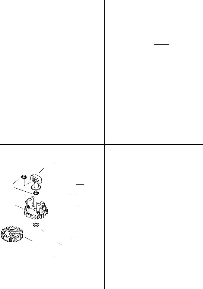
Medium Frame Horizontal |
OHM120 - OHSK 80-130 |
|||||||||||
Models: HH60,70 - H50,60,70 - HM70,80,100 - |
|
|
|
|
|
|
|
|
|
|
|
|
HMSK |
|
|
|
|
|
|
|
|
|
|
|
|
SHAFT |
|
|
|
|
|
SPOOL |
||||||
|
|
|
|
|
||||||||
|
|
|
|
|
|
|
|
|
|
|
|
|
|
|
|
|
|
|
|
|
|
WASHER |
|||
|
|
|
|
|
|
|
|
|||||
ROD ASSY. |
|
|
|
|
|
|
|
|
|
RETAINING |
||
|
|
|
|
|
|
|
|
|
||||
|
|
|
|
|
|
|
|
|
RING |
|||
(GOV.) |
|
|
|
|
|
|
|
|
|
|
|
|
|
|
|
|
|
|
|
|
|
|
|
|
GEAR ASSY. |
SPOOL |
|
|
|
|
|
|
|
|
|
|
|
(GOV.) |
|
|
|
|
|
|
|
|
|
|
|
|
|
WASHER |
|
|
|
|
|
|
|
WASHER |
||||
RETAINING |
|
|
|
|
|
|
|
|||||
|
|
|
|
|
|
|
|
|
|
|
|
|
|
|
|
|
|
|
|
|
|
|
|
|
|
RING |
|
|
|
|
|
|
SPACER |
|
|
|||
|
|
|
|
|
|
|
|
|||||
GEAR |
|
|
|
|
|
|
|
|
|
|
|
|
|
|
|
|
|
|
|
|
|
|
|
|
|
ASSY. |
|
|
|
|
|
|
|
|
|
|
|
|
(GOV) |
|
|
|
|
|
|
|
|
|
|
|
|
BRACKET |
|
|
|
|
|
|
|
|
|
|
|
|
|
|
|
|
|
|
|
|
SHAFT |
||||
SCREWS
OVM120, OVXL120, 125 - OHV11-17 |
OH120, 140, 160, 180 |
|||||||||||||||||||
|
|
|
|
|
SPOOL |
|
|
|
|
|
|
|
SPOOL |
|||||||
|
|
|
|
|
|
|
|
|
|
|
|
|||||||||
|
|
|
|
|
|
|
|
|
WASHER |
|
|
|
|
|
|
|
||||
|
|
|
|
|
|
|
|
|
|
|
|
|
|
|
|
|||||
|
|
|
|
|
|
|
|
|
|
|
|
|
|
|
|
|
|
|||
|
|
|
|
|
|
|
|
|
|
|
|
|
|
|
|
|
||||
|
|
|
|
|
|
|
|
|
|
RETAINING |
|
|
|
|
|
|
|
|
|
|
|
|
|
|
|
|
|
|
|
|
|
|
|
|
|
|
|
|
|
||
|
|
|
|
|
|
|
|
|
|
RING |
|
|
|
|
|
|
|
|
|
|
|
|
|
|
|
|
|
|
|
|
|
GEAR ASSY. |
|
|
|
|
|
WASHER |
|||
|
|
|
|
|
|
|
|
|
|
|
|
|
|
|
|
|||||
|
|
|
|
|
|
|
|
|
|
|
|
|
|
|
|
|
|
|
|
|
|
|
|
|
|
|
|
|
|
|
|
(GOV.) |
|
|
|
|
|
|
|
|
|
|
|
|
|
|
|
|
|
WASHER |
|
|
|
|
|
|
|
|
GEAR & |
|||
|
|
|
|
|
|
|
|
|
|
|
|
|
|
|
|
|||||
|
|
|
|
|
|
|
SPACER |
|
|
|
|
|
|
|
|
|||||
|
|
|
|
|
|
|
|
|
|
|
|
|
|
|
||||||
|
|
|
|
|
|
|
||||||||||||||
|
|
|
|
|
|
|
|
|
|
|
NOTE; SPACER |
|
|
|
|
|
|
|
|
SHAFT |
|
|
|
|
|
|
|
|
|
|
|
MAY BE PART |
|
|
|
|
|
|
|
|
ASSY. |
|
|
|
|
|
|
|
|
|
|
|
OF THE GEAR |
|
|
|
|
|
|
|
|
(GOV.) |
|
|
|
|
|
|
|
|
|
|
|
ASSEMBLY. |
|
|
|
|
|
|
|
|
|
|
|
|
|
|
|
|
|
SHAFT |
|
|
|
|
|
|
|
|
|
|||
|
|
|
|
|
|
|
|
|
|
|
|
|
|
|
|
|
WASHER |
|||
|
|
|
|
|
|
|
|
|
|
|
|
|
|
|
|
|
||||
|
|
|
|
|
|
|
|
|
|
|
|
|
|
|
|
|
(CAPTURED UNDER |
|||
NOTE: On models OHV13.5-17, the spacer is cast as part |
|
|
|
|
|
GEAR) |
||||||||||||||
|
|
|
|
|
|
|
|
|
||||||||||||
of the governor gear with the washer placed below the gear assembly.
16

Engine Speed and Mixture
Adjustments
3-5 H.P. Vertical Shaft Engines
NOTE: Starting and operating problems may exist when engines are used at high elevations (over 4,000 feet above sea level). In cases where a fixed main carburetor is used, refer to Bulletin 110 for correction. Engines which are identified as compliant with CARB (California Air Resources Board) or EPA (US Environmental Protection Agency) regulations can NOT be changed from their factory jetting unless specifically authorized.
Before making any speed or carburetor adjustments be sure to adjust the governor and control bracket. See Governor Section of the Booklet.
To adjust the speed control bracket, determine whether the carburetor is an adjustable type, then proceed.
Some carburetors may have a choke lever which is operated by the speed control bracket. To adjust the speed control bracket for full choke operation, loosen the speed control bracket mounting bolts and move the speed control lever to the high speed/full choke position. Next insert a small piece of wire through the hole in the speed control bracket, choke actuating lever, and the choke lever (diag. 18). When all three holes are aligned tighten the mounting bolts.
Once the speed control bracket is adjusted, the main and idle fuel mixtures can be adjusted. Start the engine and allow it to warm up to normal operating temperature (3 - 5 minutes). Set the speed control to the HIGH or FAST position, then turn the main mixture adjustment screw in (clockwise) slowly until the engine begins to run erratic (lean). Note the position of the screw. Now, turn the screw out (counterclockwise) until the engine begins to run erratic (rich). Turn the screw in (clockwise) midway between these two positions. This will be the best setting.
Set the speed control to the IDLE or SLOW position. Adjust the idle mixture screw following the same procedure used to adjust the main mixture adjustment.
NOTE: SOME CARBURETORS HAVE FIXED MAIN JETS. THE ABSENCE OF THE ADJUSTING SCREW INDICATES A FIXED JET AND NO ADJUSTMENT IS NECESSARY.
After adjusting the fuel mixtures, engine speeds can be adjusted. The correct operating speeds are found on Microfiche card 30 of the Tecumseh Master Parts Manual, or the computer parts look-up program (Part Smart). On engines with adjustable carburetors (diag. 19 and 20) the high speed adjustment will be in one of two places. The first location is on the speed control lever (diag. 19).
|
|
** NON-ADJUSTABLE |
||
* ADJUSTABLE |
NO CHOKE |
|
||
PRIMER |
|
|||
MIXTURES, CHOKE |
17 |
|||
|
||||
SPEED CONTROL |
SMALL WIRE (DRILL BIT) |
|||
MOUNTING BOLTS |
|
|
||
|
|
HOLE IN BRACKET |
|
|
|
|
|
|
|
HOLE IN SPEED
CONTROL CHOKE
ACTUATING LEVER
|
HOLE IN CHOKE |
|
LEVER |
|
18 |
HIGH SPEED |
LOW SPEED |
ADJUSTMENT SCREW |
ADJUSTMENT SCREW |
IDLE MIXTURE |
|
MIXTURE |
|
|
|||
SCREW |
|
SCREW |
19 |
17
Engine Speed and Mixture Adjustments - continued
3-5 H.P. Vertical Shaft Engines
HIGH SPEED |
LOW SPEED |
SPEED CONTROL |
|
ADJUSTMENT SCREW |
|||
ADJUSTMENT |
MOUNTING BOLTS |
||
|
|||
SCREW |
|
|
COUNTERCLOCKWISE
TO INCREASE SPEED
CLOCKWISE TO
DECREASE SPEED
IDLE
MIXTURE
SCREW
HIGH SPEED MAIN MIXTURE SCREW 20 ADJUSTMENT
SCREW
The second is on a bracket located between the blower housing and the speed control (diag. 20). Low speed is adjusted by the throttle crack screw on the carburetor (diag. 19 and 20).
It may be necessary to preset the carburetor mixture screws.
21
LOW SPEED ADJUSTMENT SCREW
Tecumseh Carburetors |
|
|
|
|
Engine Model |
Main Pre-set |
Idle Pre-set |
22 |
|
All models with |
|
|
|
|
float-type carburetors |
1-1/2 turn |
1 turn |
|
|
|
|
|
|
|
All models with |
|
|
SPEED ADJUSTMENT TAB |
|
diaphragm-type |
|
|
||
|
|
BEND |
TO INCREASE SPEED |
|
|
|
|
||
carburetors |
1 turn |
1 turn |
|
|
|
|
|
BEND |
TO DECREASE SPEED |
Some speed control brackets are adjusted by loosening the speed control bracket mounting bolts and sliding the bracket all the way to the right and retightening the mounting bolts (diag. 21). The high speed adjustment screw is located on the speed control lever (diag.22) Some carburetors are fixed speed and are adjusted by bending the adjusting tab attached to the intake manifold (diag. 23).
23
After setting the engine speeds recheck the fuel mixtures, then recheck the engine speeds.
18

Engine Speed and Mixture Adjustments - continued
3-5 H.P. Vertical Shaft Engines
LOW SPEED TAB |
HIGH SPEED TAB |
BEND |
TO INCREASE SPEED |
|
BEND |
TO DECREASE SPEED |
|
||
|
|
|
||
HIGH SPEED |
|
|
|
|
PIN POSITION |
|
|
|
|
|
|
|
BEND CONTROL |
|
|
|
|
BRACKET TO SET |
|
|
|
|
|
RPM |
TOOL |
DECREASE |
|
|
|
|
|
|
|
|
(670326) |
INCREASE |
|
|
|
|
|
|
|
|
SNAP IN CONTROL |
24 |
VERTICAL ENGINES |
25 |
|
GOVERNED / NON-GOVERNED IDLE
With the engine running at its lowest speed, set the governed idle at the designated R.P.M. by bending the idle R.P.M. tab. Next set the non-governed idle by pushing the bottom of the governor lever away from the control brackets, so the throttle lever contacts the idle speed screw. Hold the lever in this position and turn the idle adjustment screw clockwise to increase or counterclockwise to decrease engine idle speed. The setting on the carburetor screw should be set at 600 R.P.M. below the governed idle setting. This setting prevents the throttle plate from closing when going from high speed R.P.M. to low speed R.P.M. If improperly adjusted, the engine could experience an over lean condition.
HIGH SPEED RPM |
HIGH SPEED |
||
ADJUSTMENT |
|||
RPM |
|||
SCREW |
|||
ADJUSTMENT |
|||
|
|||
|
SCREW |
|
|
|
|
||
IDLE SPEED
CRACK SCREW
TVS 115 ENGINE WITH DUAL |
|
VERTICAL SHAFT ENGINES |
|
SYSTEM CARBURETOR |
26 |
27 |
BEND  TO INCREASE SPEED BEND
  TO DECREASE SPEED
NOTE:
ON REMOTE CONTROL THIS WILL NOT BE PRESENT 
HIGH SPEED ADJUST
LOW SPEED ADJUST
TNT 100 VERTICAL ENGINES |
28 |
OVRM |
29 |
19

VLV Governor and Linkage
Governor Adjustment
With the engine stopped, loosen the screw holding the governor clamp and lever. Turn the clamp clockwise, then push the governor lever (connected to the throttle) to a full wide open throttle position. Hold the lever and clamp in this position and tighten the screw.
Linkage Installation
The solid link is always connected from the throttle lever on the carburetor to the lower hole on the governor lever. The shorter bend has to be toward the governor. The governor extension spring is connected with the spring end hooked into the upper hole of the governor lever and the extension end hooked through the speed control lever. To remove the governor spring, carefully twist the extension end counterclockwise to unhook the extension spring at the speed control lever. Do not bend or distort the governor extension spring (diag. 30).
Speed Controls
This engine has an adjustable speed control. Never exceed the manufacturer's recommended speeds.
NOTE:Governor adjustment screw will be a Torx head (T-10) effective August 1, 1996 for E.C. Compliance.
Fixed Speed
High speed governor adjustment is accomplished by bending a tab to increase and decrease engine R.P.M. Effective August 1997 (diag. 31a).
TWIST COUNTERCLOCKWISE
TO DISCONNECT
GOVERNOR SPRING

 SHORT BEND
LONG BEND
30
HIGH SPEED ADJUSTMENT
COUNTERCLOCKWISE INCREASES SPEED
LOWSPEEDADJUSTMENT
COUNTERCLOCKWISEINCREASESSPEED
31
TOOL 670326
HIGHSPEED |
BEND |
|
TO INCREASE SPEED |
|
|
|
|
||||
ADJUSTMENT |
BEND |
|
|
TO DECREASE SPEED |
|
|
|
||||
|
FIXED SPEED |
31A |
|||
20
Engine Speed and Mixture
Adjustments
5-15 HP Vertical Shaft Engines
The first stepis adjusting the speed control bracket for full choke operation. Loosen the two speed control bracket mounting bolts and move the control lever to the full high speed/full choke position. Insert a piece of wire through the hole in the speed control bracket, the choke actuating lever, and the choke lever (diag. 32). When all three holes are in alignment retighten the speed control bracket mounting bolts.
SMALL PIECE OF WIRE |
HOLE IN |
HOLE IN CONTROL BRACKET |
CHOKE |
|
ACTUATING |
MOUNTING |
LEVER |
BOLTS |
|
MOVE THE CONTROL |
|
|
LEVER IN THE HIGH |
HOLE IN CHOKE LEVER |
|
SPEED POSITION |
||
|
The second step is adjusting the main and idle fuel mixtures. Start the engine and allow it to warm up to normal operating temperature (3 - 5 minutes). Set the speed controls to the HIGH or FAST position, then turn the main mixture adjustment screw in (clockwise) slowly until the engine begins to run erratic (lean). Note the position of the screw. Now, turn the screw out (counterclockwise) until the engine begins to run erratic (rich). Turn the screw in (clockwise) midway between these two positions. This will be the best setting.
Set the speed control to the IDLE or SLOW position. Adjust the idle mixture screw following the same procedure used to adjust the main mixture adjustment screw.
NOTE: SOME CARBURETORS HAVE FIXED MAIN JETS. THE ABSENCE OF THE ADJUSTING SCREW INDICATES A FIXED JET AND NO ADJUSTMENT IS NECESSARY.
The third step is setting engine speeds. The correct engine operating speeds are listed on card 30 of the Tecumseh Master parts manual microfiche, or the computer parts look-up program (Part Smart or Plus One). The most common speed control bracket (diag. 33) has the high speed adjustment screw located on the speed control lever. The low speed adjustment screw is the throttle crack screw on the carburetor body. Another common speed control is the governor override system (diag. 34). This system has a similar speed control bracket along with a governor adjustment lever which is attached to the engine block. Both the high speed and low speed adjustment screws are located on the governor adjusting lever.
32
HIGH SPEED
ADJUSTMENT SCREW
 THROTTLE
CRACK
SCREW
IDLE MIXTURE
SCREW
SCREW 33
THROTTLE CRACK SCREW
GOVERNOR
ADJUSTING LEVER
IDLE
MIXTURE
HIGH SPEED
SCREW
ADJUSTMENT
SCREW
MAIN
SCREW LOW SPEED
ADJUSTMENT SCREW
34
21
 Loading...