


TECUMSEH OHH50 - 65, OHHSK50 - 130, OHV11, OVM120, OVRM40-675 User Manual
...TECUMSEH
T E C H N I C I A N ' S H A N D B O O K
This manual covers engine models:
OHH50 - 65, OHHSK50 - 130, OHV11 - OHV17, OVM120,
OVRM40-675, OVRM120, OVXL/C120, OVXL120, OVXL125.
Other illustrated Tecumseh 2-Cycle Engine, 4-Cycle Engine and Transmission manuals; booklets; and wall charts are available through Tecumseh.
For complete listing write or call
CONTAINS SEARS CRAFTSMAN CROSS REFERENCE
4-CYCLE OVERHEAD VALVE
ENGINES 
Small Engine Parts

CONTENTS
|
Page |
CHAPTER 1 GENERAL INFORMATION ....................... |
1 |
ENGINE IDENTIFICATION ............................................. |
1 |
INTERPRETATION OF MODEL NUMBER ..................... |
1 |
SHORT BLOCKS ............................................................. |
2 |
FUELS ............................................................................. |
2 |
ENGINE OIL .................................................................... |
2 |
CAPACITIES .................................................................... |
2 |
OIL CHANGE INTERVALS .............................................. |
3 |
OIL CHECK ...................................................................... |
3 |
OIL CHANGE PROCEDURE .......................................... |
3 |
TUNE-UP PROCEDURE ................................................. |
3 |
STORAGE ....................................................................... |
4 |
DRAINING THE FUEL SYSTEM ..................................... |
4 |
OIL CYLINDER BORE .................................................... |
4 |
CHAPTER 2 AIR CLEANERS ....................................... |
5 |
GENERAL INFORMATION ............................................. |
5 |
OPERATION .................................................................... |
5 |
COMPONENTS ............................................................... |
5 |
TROUBLESHOOTING OR TESTING ............................. |
6 |
SERVICE ......................................................................... |
6 |
DISASSEMBLY PROCEDURE ....................................... |
6 |
POLYURETHANE-TYPE FILTER ELEMENT |
|
OR PRE-CLEANER..................................................... |
7 |
PAPER -TYPE FILTER ELEMENT ................................. |
7 |
FLOCKED SCREEN ........................................................ |
7 |
CHAPTER 3 CARBURETORS AND FUEL SYSTEMS . 8 |
|
GENERAL INFORMATION ............................................. |
8 |
OPERATION .................................................................... |
8 |
FUEL PRIMERS .............................................................. |
9 |
IMPULSE FUEL PUMPS ................................................. |
9 |
FLOAT STYLE CARBURETORS .................................... |
9 |
CARBURETOR VISUAL IDENTIFICATION .................... |
10 |
SERIES I CARBURETORS ............................................. |
10 |
SERIES III & SERIES IV CARBURETORS .................... |
10 |
SERIES VI CARBURETORS .......................................... |
10 |
SERIES VII ...................................................................... |
10 |
SERIES VIII ..................................................................... |
11 |
SERIES IX ....................................................................... |
11 |
WALBRO MODEL LMK ................................................... |
11 |
TESTING ......................................................................... |
12 |
SERVICE ......................................................................... |
12 |
CARBURETOR PRE-SETS AND ADJUSTMENTS ........ |
12 |
PRE-SETS AND ADJUSTMENTS |
|
(TECUMSEH AND WALBRO CARBURETORS) ......... |
13 |
FINAL ADJUSTMENTS ................................................... |
13 |
TECUMSEH CARBURETORS ........................................ |
13 |
WALBRO CARBURETOR ............................................... |
13 |
CARBURETOR DISASSEMBLY PROCEDURE ............. |
14 |
IMPULSE FUEL PUMP ................................................... |
15 |
FLOAT ADJUSTING PROCEDURE ................................ |
16 |
INSPECTION ................................................................... |
16 |
THROTTLE AND CHOKE ............................................... |
16 |
IDLE AND HIGH SPEED MIXTURE ADJUSTING |
|
SCREW ........................................................................ |
16 |
FUEL BOWL RETAINING NUT ....................................... |
16 |
FUEL BOWL, FLOAT, NEEDLE AND SEAT ................... |
17 |
ASSEMBLY PROCEDURE ............................................. |
18 |
WELCH PLUGS ............................................................... |
18 |
THROTTLE SHAFT AND PLATE .................................... |
18 |
CHOKE SHAFT AND PLATE .......................................... |
19 |
FUEL INLET FITTING ..................................................... |
19 |
HIGH AND LOW SPEED ADJUSTING SCREW, |
|
MAIN NOZZLE ............................................................. |
19 |
|
Page |
INLET NEEDLE AND SEAT ............................................ |
20 |
FLOAT INSTALLATION ................................................... |
20 |
FUEL BOWL AND BOWL NUT ....................................... |
21 |
IMPULSE FUEL PUMP ................................................... |
21 |
PRIMER BULB ................................................................ |
21 |
FINAL CHECKS ............................................................... |
21 |
CHAPTER 4 GOVERNORS AND LINKAGE ................. |
22 |
GENERAL INFORMATION ............................................. |
22 |
OPERATION .................................................................... |
22 |
TROUBLESHOOTING .................................................... |
22 |
ENGINE OVERSPEEDING ............................................. |
22 |
ENGINE SURGING ......................................................... |
22 |
SERVICE ......................................................................... |
23 |
GOVERNOR ADJUSTMENT .......................................... |
23 |
GOVERNOR GEAR AND SHAFT SERVICE .................. |
23 |
GOVERNOR GEAR OR SHAFT REPLACEMENT, |
|
UPSET STYLE GOVERNOR SHAFT .......................... |
23 |
GOVERNOR SHAFT REPLACEMENT, RETAINING |
|
RING STYLE ................................................................ |
24 |
SPEED CONTROLS AND LINKAGE .............................. |
25 |
CONVERSION TO REMOTE CONTROL ....................... |
27 |
OVM, OVXL, OHV VERTICAL SPEED CONTROL ........ |
28 |
OHV 11-17 HORIZONTAL SPEED CONTROL............... |
28 |
CHAPTER 5 RECOIL STARTERS ................................. |
29 |
GENERAL INFORMATION ............................................. |
29 |
OPERATION .................................................................... |
29 |
COMPONENTS ............................................................... |
29 |
SERVICE ......................................................................... |
29 |
ROPE SERVICE .............................................................. |
29 |
ROPE RETAINER REPLACEMENT ............................... |
30 |
STYLIZED REWIND STARTER (OHH, OVRM, OHM, |
|
OHSK, OVM, OVXL, OHV 11-13), AND STAMPED |
|
STEEL STARTER ......................................................... |
30 |
DISASSEMBLY PROCEDURE ....................................... |
30 |
ASSEMBLY PROCEDURE ............................................. |
31 |
STYLIZED REWIND STARTER WITH PLASTIC |
|
RETAINER .................................................................... |
31 |
DISASSEMBLY PROCEDURE ....................................... |
31 |
ASSEMBLY ...................................................................... |
32 |
KEEPER SPRING STYLE STARTERS .......................... |
32 |
DISASSEMBLY PROCEDURE ....................................... |
32 |
ASSEMBLY PROCEDURE ............................................. |
33 |
STYLIZED STARTER (OHV 13.5 -17) ............................ |
34 |
ASSEMBLY ...................................................................... |
34 |
CHAPTER 6 ELECTRICAL SYSTEMS .......................... |
35 |
GENERAL INFORMATION ............................................. |
35 |
OPERATION .................................................................... |
35 |
STARTING CIRCUIT AND ELECTRIC STARTERS ....... |
35 |
CHARGING CIRCUIT ...................................................... |
35 |
CONVERTING ALTERNATING CURRENT TO |
|
DIRECT CURRENT ...................................................... |
36 |
HALF WAVE RECTIFIER SINGLE DIODE ..................... |
36 |
FULL WAVE RECTIFIER BRIDGE RECTIFIER ............. |
36 |
COMPONENTS ............................................................... |
36 |
BATTERY......................................................................... |
36 |
WIRING ............................................................................ |
36 |
ELECTRICAL TERMS ..................................................... |
37 |
BASIC CHECKS .............................................................. |
37 |
TROUBLESHOOTING ELECTRICAL STARTER |
|
CIRCUIT FLOW CHART .............................................. |
38 |
TROUBLESHOOTING ELECTRICAL CHARGING |
|
CIRCUIT FLOW CHART .............................................. |
39 |
CTecumseh Products Company
1998 |
i |

|
Page |
TESTING PROCEDURE ................................................. |
40 |
STARTING CIRCUIT ....................................................... |
40 |
CHARGING CIRCUIT ...................................................... |
40 |
350 MILLIAMP CHARGING SYSTEM ............................ |
40 |
18 WATT A.C. LIGHTING ALTERNATOR....................... |
41 |
35 WATT A.C. .................................................................. |
41 |
2.5 AMP D.C., 35 WATT LIGHTING ............................... |
41 |
3 AMP DC ALTERNATOR SYSTEM - DIODE IN |
|
HARNESS SLEEVE ..................................................... |
42 |
5 AMP D.C. ALTERNATOR SYSTEM |
|
REGULATOR-RECTIFIER UNDER BLOWER |
|
HOUSING ..................................................................... |
43 |
3 AMP D.C. 5 AMP A.C. ALTERNATOR ......................... |
43 |
MODELS OVM/OVXL/OHV12.5 ..................................... |
44 |
MODELS OHV 13.5 - 17 (3/5 AMP SPLIT) ..................... |
44 |
MODELS OVM/OVXL/OHV12.5 |
|
(RED BETWEEN ENGINE AND DIODE) .................... |
44 |
MODELS OHV 13.5 - 17 |
|
(RED BETWEEN ENGINE AND DIODE) .................... |
45 |
7 AMP D.C. ALTERNATOR SYSTEM |
|
REGULATOR-RECTIFIER UNDER ENGINE |
|
HOUSING ..................................................................... |
45 |
10 AMP A.C. ALTERNATOR ........................................... |
46 |
16 AMP ALTERNATOR SYSTEM WITH EXTERNAL |
|
REGULATOR ................................................................ |
46 |
VOLTAGE REGULATORS .............................................. |
46 |
FUEL SHUT-DOWN SOLENOIDS .................................. |
46 |
LOW OIL SHUTDOWN SWITCHES ............................... |
47 |
LOW OIL PRESSURE SENSOR .................................... |
47 |
LOW OIL SENSOR .......................................................... |
47 |
ELECTRIC STARTER SERVICE .................................... |
48 |
12 VOLT OR 120 VOLT ELECTRIC STARTERS ........... |
48 |
INSPECTION AND REPAIR ............................................ |
49 |
BRUSH CARD REPLACEMENT..................................... |
49 |
CHAPTER 7 FLYWHEEL BRAKE SYSTEMS ............... |
50 |
GENERAL INFORMATION ............................................. |
50 |
OPERATION .................................................................... |
50 |
COMPONENTS ............................................................... |
51 |
SERVICE ......................................................................... |
51 |
BRAKE BRACKET ASSEMBLY ...................................... |
52 |
IGNITION GROUNDOUT TERMINAL ............................. |
52 |
STARTER INTERLOCK SWITCH ................................... |
52 |
CONTROL CABLE .......................................................... |
52 |
BRAKE BRACKET REPLACEMENT .............................. |
52 |
CHAPTER 8 IGNITION ................................................... |
53 |
GENERAL INFORMATION ............................................. |
53 |
OPERATION .................................................................... |
53 |
SOLID STATE IGNITION SYSTEM (CDI) ....................... |
53 |
COMPONENTS ............................................................... |
53 |
TESTING PROCEDURE ................................................. |
54 |
FOUR CYCLE IGNITION TROUBLESHOOTING ........... |
55 |
SERVICE ......................................................................... |
56 |
SPARK PLUG SERVICE ................................................. |
56 |
CONDITIONS CAUSING FREQUENT SPARK |
|
PLUG FOULING ........................................................... |
56 |
IGNITION TIMING CHECK ............................................. |
57 |
SERVICE TIPS ................................................................ |
57 |
|
Page |
CHAPTER 9 INTERNAL ENGINE AND CYLINDER |
..... 58 |
GENERAL INFORMATION ............................................. |
58 |
OPERATION .................................................................... |
58 |
4-CYCLE ENGINE THEORY .......................................... |
58 |
LUBRICATION SYSTEMS .............................................. |
59 |
COUNTERBALANCE SYSTEMS ................................... |
59 |
COMPONENTS ............................................................... |
60 |
ENGINE OPERATION PROBLEMS ............................... |
61 |
ENGINE OPERATION PROBLEMS ............................... |
62 |
TESTING ......................................................................... |
63 |
ENGINE KNOCKS ........................................................... |
63 |
ENGINE OVERHEATS .................................................... |
63 |
SURGES OR RUNS UNEVENLY ................................... |
63 |
ENGINE MISFIRES ......................................................... |
63 |
ENGINE VIBRATES EXCESSIVELY .............................. |
64 |
BREATHER PASSING OIL ............................................. |
64 |
EXCESSIVE OIL CONSUMPTION ................................. |
64 |
LACKS POWER .............................................................. |
65 |
SERVICE ......................................................................... |
65 |
DISASSEMBLY PROCEDURE ....................................... |
65 |
CYLINDERS .................................................................... |
68 |
CYLINDER HEAD AND VALVE TRAIN SERVICE ......... |
69 |
VALVES, SPRINGS, AND PUSH RODS ........................ |
69 |
PISTONS, RINGS, AND CONNECTING RODS ............. |
70 |
PISTON ........................................................................... |
70 |
PISTON RINGS ............................................................... |
70 |
PISTON RING ORIENTATION ....................................... |
70 |
CONNECTING RODS ..................................................... |
71 |
CRANKSHAFTS AND CAMSHAFTS .............................. |
71 |
CAMSHAFTS ................................................................... |
71 |
VALVE SEATS ................................................................. |
72 |
VALVE LIFTERS .............................................................. |
73 |
VALVE GUIDES ............................................................... |
73 |
VALVE GUIDE REMOVAL (OVM, OHM, OHSK110 |
|
& 120, OVXL ONLY) .................................................... |
73 |
VALVE GUIDE INSTALLATION (OVM, OHM, |
|
OHSK110 & 120, OVXL ONLY) ................................... |
73 |
CRANKCASE BREATHERS ........................................... |
74 |
TOP MOUNTED BREATHER ......................................... |
74 |
SIDE MOUNTED BREATHER ........................................ |
74 |
CYLINDER COVER, OIL SEAL, AND BEARING |
|
SERVICE ...................................................................... |
75 |
CYLINDER COVER ........................................................ |
75 |
OIL SEAL SERVICE ........................................................ |
75 |
CRANKSHAFT BEARING SERVICE .............................. |
75 |
BALL BEARING SERVICE .............................................. |
75 |
SERVICE BUSHING ....................................................... |
76 |
BUSHING SIZE CHART.................................................. |
76 |
ENGINE ASSEMBLY ...................................................... |
76 |
CHAPTER 10 .................................................................. |
83 |
ENGINE SPECIFICATIONS AND SEARS |
|
CRAFTSMAN CROSS-REFERENCE ......................... |
83 |
OVERHEAD VALVE SEARS CRAFTSMAN |
|
CROSS REFERENCE ................................................. |
83 |
ENGINE SPECIFICATIONS............................................ |
85 |
OVERHEAD VALVE TORQUE SPECIFICATIONS ........ |
86 |
OVERHEAD VALVE TORQUE SPECIFICATIONS ........ |
87 |
CHAPTER 11 EDUCATIONAL MATERIALS |
|
AND TOOLS ............................................................... |
88 |
Copyright © 1994 by Tecumseh Products Company
All rights reserved. No part of this book may be reproduced or transmitted, in any form or by any means, electronic or mechanical, including photocopying, recording or by any information storage and retrieval system, without permission in writing from Tecumseh Products Company Training Department Manager.
ii
CHAPTER 1 GENERAL INFORMATION
ENGINE IDENTIFICATION
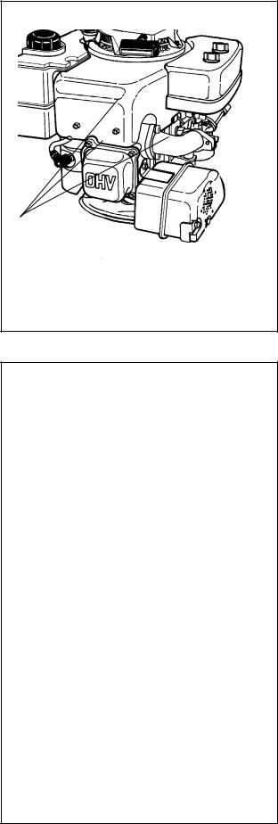
Tecumseh engine model, specification, and serial numbers or date of manufacture (D.O.M.) are stamped into the blower housing, or located on a decal on the engine in locations as illustrated (diag. 1 & 2). The engine identification decal also provides the applicable warranty code and oil recommendations (diag. 2).
Interpretation of Model Number
The letter designations in a model number indicate the basic type of engine.
OHH |
- |
Overhead Valve Horizontal |
OHM |
- |
Overhead Valve Horizontal |
|
|
MediumFrame |
OHSK |
- Overhead Valve Horizontal Snow King |
|
OVM |
- Overhead Valve Vertical Medium Frame |
|
OVRM |
- Overhead Valve Vertical Rotary Mower |
|
OVXL |
- Overhead Valve Vertical Medium Frame |
|
|
|
Extra Life |
OHV |
- |
Overhead Valve Vertical |
The number designations following the letters indicate the basic engine model.
The number following the model number is the specification number. The last three numbers of the specification number indicate a variation to the basic engine specification.
The serial number or D.O.M. indicates the production date of the engine.
Using model OHV16-204207A, serial 5215C as an example, interpretation is as follows:
OHV16-204207A is the model and specification number.
OHV Overhead Valve Vertical
16 Indicates the basic engine model.
204207A is the specification number used for properly identifying the parts of the engine.
5215C is the serial number or D.O.M. (Date of Manufacture)
5is the last digit in the year of
manufacture (1995).
215indicates the calendar day of that year (215th day or August 3, 1995).
Crepresents the line and shift on which the engine was built at the factory.
Emissionized engines that meet the California Air Resource Board (C.A.R.B.) or the Environmental Protection Agency (E.P.A.) standards will include additional required engine information on the engine decal.
NOTE: To maintain best possible emission performance, use only Genuine Tecumseh Parts.
ENGINE MODEL
NUMBER
1
THIS ENGINE MEETS 1995-1998
CALIF. EMISSION REGULATIONS FOR
ULGE ENGINES AS APPLICABLE
FUEL: REGULAR UNLEADED OIL : USE SAE 30
OHV 125 203000A |
(D) |
RTP358UIG2RA |
|
358cc |
3057D |
2
1
SHORT BLOCKS
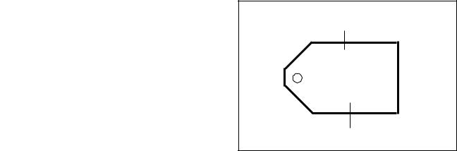
New short blocks are identified by a tag marked S.B.H. (Short Block Horizontal) or S.B.V. (Short Block Vertical). Original model identification numbers of an engine should always be transferred to a new short block for correct parts identification (diag. 3).
THIS SYMBOL POINTS OUT IMPORTANT SAFETY INSTRUCTIONS WHICH IF NOT FOLLOWED COULD ENDANGER THE PERSONAL SAFETY OF YOURSELF AND OTHERS. FOLLOW ALL INSTRUCTIONS.
FUELS
SBV OR SBH IDENTIFICATION NUMBER
SHORT BLOCK IDENTIFICATION TAG
SBV564A
SER 5107
SERIAL NUMBER
3
Tecumseh Products Company strongly recommends the use of fresh, clean, unleaded regular gasoline in all Tecumseh Engines. Unleaded gasoline burns cleaner, extends engine life, and promotes good starting by reducing the build up of combustion chamber deposits. Unleaded regular, unleaded premium or reformulated gasoline containing no more than 10% Ethanol, or 15% MTBE, or 15% ETBE may also be used.
Leaded fuel is generally not available in the United States and should not be used if any of the above options are available.
Never use gasoline, fuel conditioners, additives or stabilizers containing methanol, white gas, or fuel blends which exceed the limits specified above for Ethanol, MTBE, or ETBE because engine/fuel system damage could result.
Regardless of which of the approved fuels are used, fuel quality is critical to engine performance. Fuel should not be stored in an engine or container more than 30 days prior to use. This time may be extended with the use of a fuel stabilizer like TECUMSEH'S, part number 730245.
See "STORAGE" instructions in the Technician's Manual, Operators Manual, or Bulletin 111.
ENGINE OIL
TECUMSEH FOUR CYCLE ENGINES REQUIRE THE USE OF A CLEAN, HIGH QUALITY DETERGENT OIL. Be sure original container is marked: A.P.I. service "SF" thru "SJ" or "CD".
TECUMSEH RECOMMENDS USING ONE OF THE FOLLOWING FOUR CYCLE OILS THAT ARE SPECIALLY FORMULATED TO TECUMSEH SPECIFICATIONS.
DO NOT USE SAE10W40 OIL.
FOR SUMMER (Above 320 F) (0oC) USE SAE30 OIL. PART #730225
Use SAE30 oil in high temperature, high load applications. Using multigrade oil may increase oil consumption. FOR WINTER (Below 320F) (0oC) USE SAE5W30 OIL. PART #730226
(SAE 10W is an acceptable substitute.)
(BELOW 00F (-18oC) ONLY): SAE 0W30 is an acceptable substitute.
NOTE: For severe, prolonged winter operation of HH120 model, SAE10W oil is recommended.
Capacities
Engine Model |
|
Oz. |
|
ml. |
|
OHH,OHSK 50-70 |
21 |
630 |
|||
OVRM 40 - 6.75 |
21 |
630 |
|||
OVRM105 & 120 |
21 |
630 |
|||
OHSK80 - 100 |
|
26 |
720 |
||
OHM, OHSK 110* - 130 |
32 |
960 |
|||
OVM 120, OVXL 120, 125 |
32 |
960 |
|||
OHV 11 - 13 without oil filter |
32 |
960 |
|||
OHV 11 - 13 with filter |
39 |
1170 |
|||
OHV 13.5 |
- 17 |
without oil filter |
55 |
1650 |
|
OHV 13.5 |
-17 |
2 1/4" filter (part # 36563) |
62 |
1860 |
|
OHV 13.5 |
-17 |
2 5/8" filter (part # 36262) |
64 |
1920 |
|
* NOTE: Model OHSK110 with a spec. of 221000 and up, have a capacity of 26 oz. (720 ml.)
2

Oil Change Intervals: Change the oil after the first two (2) hours of operation and every 25 hours thereafter (OHH & OHSK50-130, OHV13.5-17 every 50 hours), or more often if operated under dusty or dirty conditions. If the engine is run less than 25 hours per year, change the oil at least once per year.
NOTE: The oil filter (if equipped) requires changing every 100 hours or more often if operated under dusty or dirty conditions.
Oil Check: Check the oil each time the equipment is used or every five (5) hours of operation. Position the equipment so the engine is level when checking the oil.
 CAUTION: Remove the spark plug wire before doing any service work on the engine.
Oil Change Procedure: Locate the oil drain plug. On some units this plug is located below the deck through the bottom of the mounting flange. Other units drain at the base of the engine above the deck or frame. On some rotary mower applications, where access to the drain plug is restricted by the equipment, it may be necessary to drain the oil by tipping the mower in a position that would allow the oil to drain out of the fill tube.
On units that the drain plug is accessible, remove the plug and allow the oil to drain into a proper receptacle. Always make sure that drain oil is disposed of properly. Contact your local governing authorities to find a waste oil disposal site.
Once the oil is drained, reinstall the drain plug and fill the engine with new oil to the proper capacity.
TUNE-UP PROCEDURE:
NOTE: Today's fuels can cause many problems in an engines performance due to the fuels quality and short shelf life. Always check fuel as a primary cause of poor engine performance.
The following is a minor tune-up procedure. When this procedure is completed, the engine should operate properly. Further repairs may be necessary if the
engine's performance remains poor. |
STANDARD |
OHV |
|
|
CAUTION: Remove the spark plug wire |
PLUG |
|
|
|
|
|
|
before doing any service work on the engine. |
|
|
1. |
Service or replace the air cleaner. See |
|
|
|
Chapter 2 under "Service". |
|
|
2. |
Inspect the level and condition of the oil and |
|
|
|
change or add oil as required. |
|
|
3. |
Remove the blower housing and clean all dirt, |
|
|
|
grass or debris from the intake screen, head, |
|
|
|
cylinder cooling fins, carburetor, governor |
|
|
|
levers and linkage. |
|
|
4. |
Make sure the fuel tank, fuel filter and fuel |
|
4 |
|
line are clean. Replace any worn or damaged |
|
|
|
|
|
|
governor springs or linkage. Make the proper governor adjustments and carburetor presets where required.
5.When replacing the spark plug, consult the proper parts breakdown for the spark plug to be used in the engine being serviced. Set the proper spark plug gap (.030") (.762 mm) and install the spark plug in the engine. Tighten the spark plug to 21 foot pounds (28 Nm) of torque. If a torque wrench isn’t available, screw the spark plug in as far as possible by hand, and use a spark plug wrench to turn the spark plug 1/8 to 1/4 turn further if using the old spark plug, or 1/2 turn further if using a new spark plug.
6.Make sure all ignition wires are free of abrasions or breaks and are properly routed so they will not rub on the flywheel.
7.Properly reinstall the blower housing, gas tank, fuel line, and air cleaner assembly if removed.
8.Make sure all remote cables are properly adjusted for proper operation. See Chapter 4 under "Speed Controls and Linkage".
9.Reinstall the spark plug wire, add fuel and oil as necessary, start the engine.
3

STORAGE (IF THE ENGINE IS TO BE UNUSED FOR 30 DAYS OR MORE)
CAUTION: NEVER STORE THE ENGINE WITH FUEL IN THE TANK INDOORS OR IN ENCLOSED, POORLY VENTILATED AREAS, WHERE FUEL FUMES MAY REACH AN OPEN FLAME, SPARK OR PILOT LIGHT AS ON A FURNACE, WATER HEATER, CLOTHES DRYER OR OTHER GAS APPLIANCE.
Gasoline can become stale in less than 30 days and form deposits that can impede proper fuel flow and engine operation. To prevent deposits from forming, all gasoline must be removed from the fuel tank and the carburetor. An acceptable alternative to removing all gasoline, is by adding Tecumseh's fuel stabilizer, part number 730245, to the gasoline. Fuel stabilizer is added to the fuel tank or storage container. Always follow the mix ratio found on the stabilizer container. Run the engine at least 10 minutes after adding the stabilizer to allow it to reach the carburetor.
Draining the Fuel System
CAUTION: DRAIN THE FUEL INTO AN APPROVED CONTAINER OUTDOORS, AND AWAY FROM ANY OPEN FLAME OR COMBUSTION SOURCE. BE SURE THE ENGINE IS COOL.
1.Remove all gasoline from the fuel tank by running the engine until the engine stops, or by draining the fuel tank by removing the fuel line at the carburetor or fuel tank. Be careful not to damage the fuel line, fittings, or fuel tank.
2.Drain the carburetor by pressing upward on bowl drain (if equipped) which is located on the bottom of the carburetor bowl. On carburetors without a bowl drain, the carburetor may be drained by loosening the bowl nut on the bottom carburetor one full turn. Allow to completely drain and retighten the bowl nut being careful not to damage the bowl gasket when tightening.
3.If "Gasohol" has been used, complete the above procedure and then put one half pint of unleaded gasoline into the fuel tank and repeat the above procedure. If Gasohol is allowed to remain in the fuel system during storage, the alcohol content can cause rubber gaskets and seals to deteriorate.
Change Oil: If the oil has not been changed recently, this is a good time to do it. See "Oil Change Procedure" on page 3.
Oil Cylinder Bore
1.Disconnect the spark plug wire and ground the spark plug wire to the engine. Remove the spark plug and put a 1/2 ounce (15 ml.) of clean engine oil into spark plug hole.
2.Cover the spark plug hole with a shop towel.
3.Crank the engine over, slowly, several times.
4.Install the spark plug and connect the spark plug wire.
Clean Engine: Remove the blower housing and clean all dirt, grass or debris from the intake screen, head, cylinder cooling fins, carburetor, governor levers and linkage.
4
CHAPTER 2 AIR CLEANERS
GENERAL INFORMATION
The air cleaner is the device used to eliminate dust and dirt from the air supply. Filtered air is necessary to assure that abrasive particles are removed before entering the combustion chamber. Dirt allowed into the engine will quickly wear the internal components and shorten the life of the engine.
Tecumseh engines use either a polyurethane or a paper-type air filter system. A polyurethane precleaner or a flocked screen may be used with the main filter. Snow King® engines do not use an air filter due to the clean operating environment and to prevent filter freeze-up.
Extremely dirty conditions may require more frequent filter cleaning or replacement.
OPERATION
The air cleaner cover allows access to the air filter element(s) and prevents large particles from entering the filter body. Air is filtered through the pre-cleaner or flocked screen if equipped, and the polyurethane or paper filter element. Pre-cleaners or flocked screens provide more air cleaning capacity.
In Tecumseh's Kleen Aire® system, air is drawn in through a rotating screen or recoil housing to be centrifugally cleaned by the flywheel before the air enters the air filter.
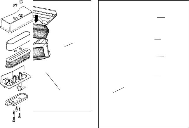
COMPONENTS
The cover holds the filter element and prevents large debris from entering the filter body.
The polyurethane wrap pre-cleaner is used on XL or XL/C engine models with paper filter elements.
The paper or polyurethane filter element is the main filter to trap dust and dirt. Dry-type paper elements are pleated paper for increased surface area and rubberized sealing edges. The polyurethane filter uses an oil film to trap fine particles found in dust.
The flocked screen is used as an additional filter on XL or XL/C engine models that use a polyurethane filter element.
COVER
KLEEN-AIRE® |
|
ENTRANCE FROM |
FOAM |
UNDER BLOWER |
ELEMENT |
HOUSING |
|
FLOCKED SCREEN
AIR CLEANER BODY
1
COVER
POLYURETHENE
WRAP
PAPER
ELEMENT
AIR CLEANER
BODY
KLEEN-AIRE®
ENTRANCE FROM
UNDER BLOWER
HOUSING
2
5
TROUBLESHOOTING OR TESTING
If the engine's performance is unsatisfactory (needs excessive carburetor adjustments, starts smoking abnormally, loses power), the first engine component to be checked is the air filter. A dirt restricted or an oil soaked filter will cause noticeable performance problems. A polyurethane filter may be cleaned following the service procedure listed under "Service" in this chapter. A paper-type air filter should only be replaced. A paper-type filter cannot have an oil film present on the paper. Follow the procedure listed in the "Service" section of this chapter for filter replacement or cleaning.
SERVICE
Service on the polyurethane filter element (cleaning and oiling) is recommended every three (3) months or every twenty five (25) operating hours, whichever comes first. Extremely dirty or dusty conditions may require daily cleanings.
The paper filter element should be replaced once a year or every 100 operating hours, more often if used in extremely dusty conditions.
NOTE: NEVER RUN THE ENGINE WITHOUT THE COMPLETE AIR CLEANER ASSEMBLY INSTALLED ON THE ENGINE. ALWAYS REPLACE THE FILTER ELEMENT WITH THE PROPER TECUMSEH ORIGINAL REPLACEMENT PART.
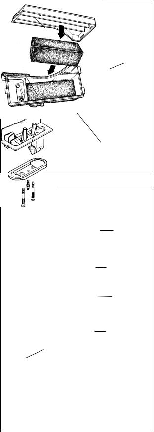
DISASSEMBLY PROCEDURE
1.Unlock the tabs or remove the screws or wing nuts holding the air cleaner cover in place.
2.Remove the hex nuts holding the element down if equipped. New nuts are supplied with a new filter and are to be used for proper sealing.
3.Clean the excess contaminants out of the air cleaner body before removing the old element.
4.Remove the old element and the polyurethane pre-cleaner if equipped.
5.On air cleaners that use a flocked screen under the polyurethane element, remove the air cleaner assembly from the carburetor before removing the flocked screen. This prevents dirt from entering the carburetor (diag 3).
6.Clean the inside of the cover and body, remove the old gasket between the carburetor and the air cleaner assembly.
7.Reinstall the air cleaner assembly using a new gasket.
8.Use reverse procedure for reassembly. When installing the polyurethane pre-cleaner, make sure the seam is installed to the outside to prevent gaps between the paper element and the pre-cleaner.
WING NUTS
|
|
|
|
|
|
|
|
COVER |
|
|
|
|
|
|
|
GASKET |
|
FILTER A |
|
|
|
|
|
|
NUTS |
|
|
|
|
|
|
|
|||
(FOAM) |
|
|
|
|
|
|
|
|
KLEEN-AIRE® |
|
|
|
|
|
|
FILTER B |
|
|
|
|
|
|
|
|||
|
|
|
|
|
|
|
|
|
ENTRANCE |
|
|
|
|
|
|
|
BODY |
COVER |
|
|
|
|
|
|
|
|
|
|
|
|
|
|
|
|
|
|
|
|
|
GASKET |
||||
FOAM |
|
|
|
|
|
|
|
|
FILTER |
|
|
|
|
|
|
|
|
KLEEN-AIRE® |
|
|
|
FLOCKED SCREEN |
||||
|
|
|
||||||
|
|
|
|
|
|
|
|
|
ENTRANCE |
|
|
|
|
|
|
|
|
GASKET |
3 |
6
Polyurethane-Type Filter Element or pre-cleaner
This type of air filter or pre-cleaner can be serviced when restricted with dust or dirt. Wash the filter or precleaner in a detergent and water solution until all the dirt is removed. Rinse in clear water to remove the detergent solution. Squeeze the filter or pre-cleaner (do not twist) to remove the excess water. Wrap the filter or pre-cleaner in a clean cloth and squeeze it (do not twist) until completely dry.
On the polyurethane filter only, re-oil the filter by applying engine oil and squeezing it vigorously to distribute the oil. Roll the filter in a cloth and squeeze it (do not twist) to remove the excess oil. The pre-cleaner must not be oiled.
Clean the air cleaner housing and cover being careful not to allow dirt to fall into the carburetor or intake pipe.
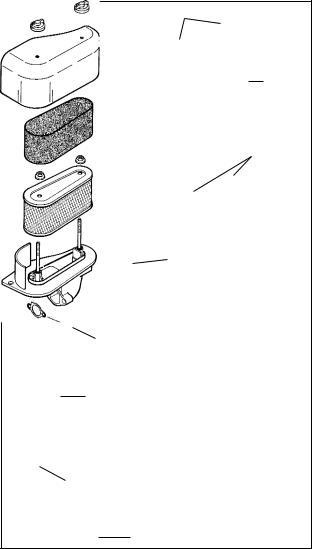
Paper -type filter element
Paper type air filter elements can only be serviced by replacement. Do not attempt to clean a paper filter element. Replacement filters are available at any authorized Tecumseh Service Outlet. Be sure to use new filter nuts or seals for the air cleaner studs if supplied with the new filter (diag. 5).
Flocked Screen
A flocked screen may be cleaned by blowing compressed air through the screen from the backside. If the screen cannot be cleaned with this procedure, it should be replaced with a new screen.
COVER
COVER
KLEEN-AIRE® |
|
POLYURETHENE |
|
ENTRANCE FROM |
FOAM |
||
WRAP |
|||
UNDER BLOWER |
ELEMENT |
|
|
HOUSING |
|
|
|
|
|
PAPER |
|
|
|
ELEMENT |
AIR CLEANER
BODY
AIR CLEANER |
FLOCKED SCREEN |
KLEEN-AIRE® |
|
||
BODY |
|
ENTRANCE FROM |
|
|
UNDER BLOWER |
|
4 |
HOUSING |
|
|
5
7
CHAPTER 3 CARBURETORS AND FUEL SYSTEMS
GENERAL INFORMATION
Tecumseh overhead valve engines use float type carburetors. Float type carburetors use a hollow float to maintain the operating level of fuel in the carburetor.
The float type carburetor will have a fuel enrichment system of either a primer or a manual choke to provide easy cold engine starting. The carburetor fuel mixtures are either fully adjustable, partially adjustable, or nonadjustable. Carburetor adjustments, cleaning, and related fuel system service is covered in this chapter.
Some Tecumseh engines utilize Walbro carburetors. Basic operation is very similar to the Tecumseh float style carburetor.
Carburetors used by Tecumseh can be identified by a manufacturing number stamping on the carburetor as
illustrated (diag. 1).
When servicing carburetors, use the engine model and specification number to obtain the correct carburetor part number. An alternate method to find the correct carburetor part number is to use the manufacturing number stamped on the carburetor and convert this number to a service part number. In the carburetor section of the Master Parts Manual or Microfiche Catalog, a cross reference chart will convert a carburetor manufacturing number to a Tecumseh Service part number.
Complete carburetor replacement may be accomplished by a standard service carburetor. A standard service carburetor is a basic carburetor that may require the use of original carburetor parts or additional new parts to adapt to the specification. An instruction sheet is provided with the new service carburetor or see “SERVICE” in this chapter.
ALTERNATE LOCATION
FOR MANUFACTURING
NUMBER
89 4F5
|
89 |
4F5 |
|
|
|
|
|
MANUFACTURING |
|
CARBURETOR |
1 |
NUMBER |
|
DATE CODE |
OPERATION
In the “CHOKE” or “START” position, the choke |
|
shutter is closed, and the only air entering the engine |
|
enters through openings around the shutter. As the |
CHOKE PLATE |
starting device is operated to start the engine, |
|
downward piston travel creates a low air pressure area |
|
in the engine cylinder above the piston. Higher |
|
pressure (atmospheric air) rushes into the engine to |
|
fill the created low pressure area. Since the majority |
|
of the air passage is blocked by the choke shutter, a |
|
relatively small quantity of air enters the carburetor |
|
at increased speed. The main nozzle and both idle |
|
fuel discharge ports are supplying fuel due to the low |
|
air pressure in the intake of the engine. A maximum |
|
fuel flow through the carburetor orifices combined with |
|
the reduced quantity of air that passes through the |
|
carburetor, make a very rich fuel mixture which is |
FLAT |
needed to start a cold engine. |
DOWN |
At engine IDLE speed, a relatively small amount of |
2 |
fuel is required to operate the engine. The throttle is |
|
almost completely closed. A fuel / air mixture is supplied through the primary idle-fuel discharge orifice during idle.
During INTERMEDIATE engine operation, a second orifice is uncovered as the throttle shutter opens, and more fuel mixture is allowed to atomize with the air flowing into the engine.
During HIGH SPEED engine operation, the throttle shutter is opened. Air flows through the carburetor at high speed. The venturi, which decreases the size of the air passage through the carburetor, further accelerates the air flow. This high speed movement of the air decreases the air pressure at the main nozzle opening. Fuel is forced out the main nozzle opening due the difference in the atmospheric air pressure on the fuel in the carburetor bowl and the reduced air pressure at the main nozzle opening.
8
For the fuel to flow, the carburetor bowl must be either vented externally or internally. Some internally vented float style carburetors use a tygon tube and a vent within the air intake. This tube must be present for the carburetor to operate properly (diag. 3).
Air is bled into the main nozzle through the air bleed located in the air horn. This mixes fuel and air prior to the fuel leaving the main nozzle. Atomization occurs as the fuel mixture contacts the fast moving air stream and the mist flows into the intake of the engine.
INTERNAL VENT |
EXTERNAL VENT |
3 |
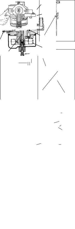
FUEL PRIMERS
Primers may be mounted remotely or as an integral part of the carburetor. The basic function of the primer is to supply an air pressure charge to the carburetor main well or carburetor bowl to displace fuel directly into the carburetor venturi. This displaced fuel provides a rich mixture necessary for engines to start easily on the first or second attempt (diag. 4 & 5).
Primers must be vented either internally through a passage in the carburetor air horn prior to the venturi or externally through a hole in the primer bulb. The vent allows atmospheric air to enter the fuel bowl during operation and to fill the primer bulb after the primer bulb is released.
IMPULSE FUEL PUMPS
Impulse fuel pumps may either be mounted externally onto the carburetor fuel inlet or remotely mounted. This pump is connected in the fuel line between the fuel supply and the carburetor or directly to the fuel inlet.
Impulse fuel pumps are operated by crankcase impulses created by the up and down movement of the piston. A hose called a pulse line connects the fuel pump diaphragm chamber to the crankcase and transmits the impulses to the pump diaphragm. The impulses actuate the diaphragm and flap valves to lift the fuel from the fuel tank to the carburetor (diag. 6). A crankcase overfilled with engine oil can affect pump operation.
FLOAT STYLE CARBURETORS
A float is used to maintain the operating level of fuel in the carburetor bowl. As the fuel is used by the engine, the fuel level in the carburetor bowl drops and the float moves downward. This allows the inlet needle valve to move off the sealing seat. Fuel flows by gravity or a pulse pump into the fuel bowl. As the fuel level in the bowl again rises, it raises the float. This upward float motion moves the inlet needle valve to the closed position. When the needle contacts the seat, the fuel flow is stopped. The tapered end of the inlet needle varies the fuel flow rate and the fuel level in the carburetor bowl remains constant (diag. 7). The float height is set according to the service procedure.
PRIMER BULB |
PRIMER BULB |
|
VENT
|
|
MAIN NOZZLE |
|
||
|
|
4 |
|
MAIN JET 5 |
|
|
|
|
|
|
|
|
|
|
|
CARBURETOR |
|
|
|
|
|
FITTING |
|
|
VALVE CLOSED |
|
VALVE OPEN |
|
|
|
|
ATMOSPHERIC |
|
|
|
|
|
|
DIAPHRAGM |
||
|
|
VENT |
|
||
|
|
|
|
|
|
|
|
|
|
FILTER |
|
|
|
|
|
AIR BLEED |
|
|
VALVE OPEN |
|
VALVE CLOSED |
||
|
|
|
|
||
|
FUEL SUPPLY |
|
PULSE LINE |
||
|
|
|
|
TO CRANKCASE |
|
êCRANKCASE PRESSURE |
êCRANKCASE SUCTION AND |
áSUCTION FUEL FLOW DIRECTION |
|||
áATMOSPHERIC PRESSURE ACTING |
FLOW DIRECTION |
|
ATMOSPHERIC PRESSURE |
|
|
á |
ON DAMPING DIAPHRAGM |
ATMOSPHERIC PRESSURE |
êCAUSED FUEL FLOW |
6 |
|
FUEL FLOW |
ACTING ON DAMPING |
|
|
||
|
á DIAPHRAGM |
|
|
||
|
|
|
|
|
|
|
|
IDLE AIR |
MAIN AIR |
|
|
|
|
BLEED |
|
|
|
|
|
|
BLEED |
|
|
|
|
|
|
|
|
|
|
|
|
CHOKE |
|
|
|
|
|
SHUTTER |
|
|
THROTTLE |
|
|
|
|
|
SHUTTER |
|
|
|
|
|
|
|
|
INLET NEEDLE |
|
IDLE |
|
|
AND SEAT |
|
|
|
|
|
|
||
ADJUSTMENT |
|
|
|
|
|
|
|
|
|
FLOAT |
|
|
MAIN NOZZLE |
MAIN |
|
|
7 |
|
|
ADJUSTMENT |
|||
9
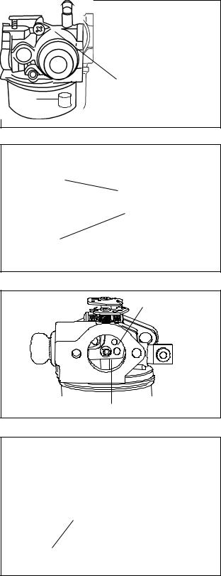
CARBURETOR VISUAL IDENTIFICATION
Series1 Carburetors
Series 1 carburetors are used on some 4 - 7 model overhead valve engines. This float style carburetor has a smaller venturi than the Series 3 or 4 carburetor and has no bosses on each side of the idle mixture screw. The main and idle mixture may be fixed or adjustable. A remote primer or choke may also be used with this carburetor (diag. 8).
Series 3 & Series 4 Carburetors
Series 3 or 4 carburetors are generally used on 8 through 14 model 4-cycle engines. The quickest way to identify these carburetors is by the presence of bosses on each side of the idle mixture screw (diag. 9).
To determine whether the carburetor is a Series 3 or Series 4, look at the throttle end of the carburetor. Series 3 will have one throttle plate screw (diag. 10). The Series 4 will have two throttle plate screws (diag. 11).
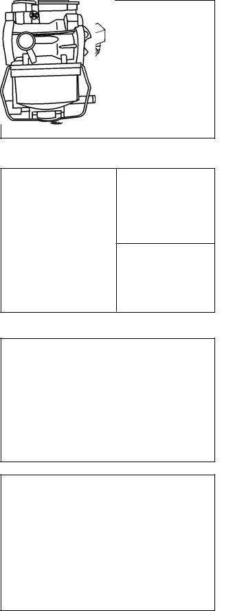
Series 6 Carburetors
Series 6 carburetors are used on 2 and 4-cycle engines in the 3 to 6 model range. Series 6 uses a simple fixed idle and fixed main fuel circuit. Series 6 carburetors are commonly used on rotary mower applications. Series 6 are nonadjustable, with a stepped primer bulb and a bowl prime system (diag. 12).
Series 7
Series 7 carburetors are totally nonadjustable. The die cast carburetor body is similar in appearance and slightly longer than the Walbro LMK body. The choke shaft is made of a plastic material with an internal slot to hold the choke shutter. The carburetor base is flat to accept a Vector style bowl that is held on with a wire bail. (diag. 13)
8
10
11
12
13
10
Series 8
Series 8 carburetors have both a fixed main and a fixed idle circuit. These carburetors are totally nonadjustable. This series of carburetor uses an integral primer system like the Series 6. Distinguish this carburetor from the Series 6 by the fixed idle jet that appears as a screw just above the bowl on the primer side. This fixed idle jet may also be capped. (diag. 14)
Series 9
Series 9 carburetors are hybrid versions of the Series 8. This carburetor uses a fixed idle jet and fixed main fuel circuit. This carburetor is totally nonadjustable. The bowl nut uses a ball plug on the bottom to cover the center drilling. Also visible is a plastic main fuel discharge nozzle in the venturi. The Idle mixing well and jet will be visible but not machined (diag. 15)
Series 10
This carburetor is for use on all season engine applications. It is the equivalent of the series "8" with the addition of a choke. It has a fixed main and idle with a serviceable main nozzle and a primer assist, with the added benefit of a choke for cold weather starting.
CAPPED FIXED
IDLE JET
CAP
14
MIXING WELL
CAST BUT NOT
MACHINED
IDLE JET CAST BUT NOT
MACHINED
15
CHOKE PLATE
FLAT SIDE DOWN |
15 |
Walbro Model LMK
OHV 15-17 models use this float-feed carburetor. The carburetor is attached to the intake pipe using studs that also fasten the air filter body. Walbro model and manufacturing numbers are found on the throttle end of the carburetor. This carburetor has a fixed, nonadjustable main mixture jet.
Idle mixture screws were adjustable on early production OHV15. This has since changed to a fixed idle jet which may be capped for tamper resistance.
If no spring is visible, the jet is fixed. Servicing should be done by a Authorized Tecumseh Dealer.
LOW IDLE |
|
MIXTURE SCREW |
16 |
MAY BE ADJUSTABLE OR FIXED |
11
TESTING
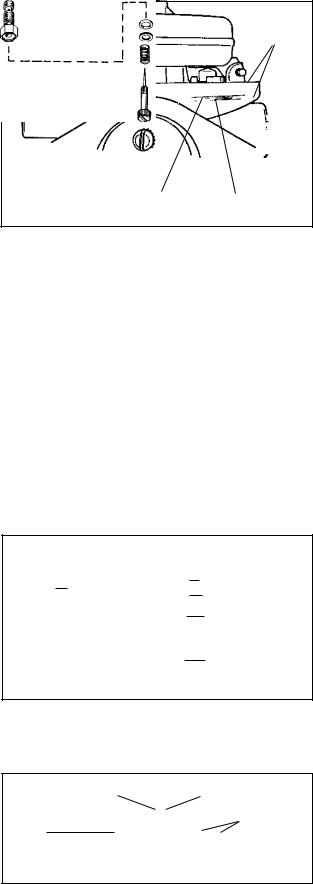
1.After repeated efforts to start the engine using the procedure listed in the operator’s manual fail, check for spark by removing the high tension lead and removing the spark plug. Install a commercially available spark tester and check for spark. If the spark is bright blue and consistent, proceed to step 2. If no or irregular spark see Chapter 8 under "Testing".
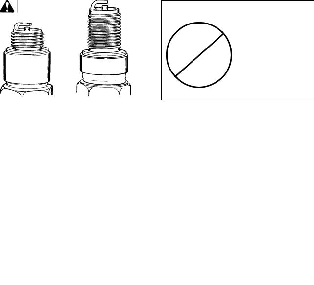
2.Visually inspect the removed spark plug for a wet condition indicating the presence of gasoline in the
cylinder.
NOTE: Check plug for correct reach (diag. 17).
3.If the spark plug is dry, check for restrictions in the fuel system before the carburetor. If the spark plug is wet, continue with step # 7.
CHECK THE FUEL CAP FOR PROPER VENTING. With a proper draining receptacle, remove the fuel line clamp on the carburetor fuel inlet and pull the fuel line off the fitting. Examine the fuel flow with the fuel cap both on and off the fuel tank.
CAUTION: DRAIN THE FUEL INTO AN
STANDARD |
OHV |
PLUG |
|
17
APPROVED CONTAINER OUTDOORS, AND AWAY FROM ANY OPEN FLAME OR COMBUSTION SOURCE. BE SURE THE ENGINE IS COOL.
NOTE: Todays fuels can cause many problems in an engines performance, due to the fuels quality and short shelf life. Always check fuel as a primary cause of engine performance.
4.Remove the air filter, heater box, or air cleaner assembly if applicable to visually check that the choke shutter completely closes or check to see if fuel comes out of the main nozzle during priming.
5.If the fuel flow from the tank is adequate and no fuel is evident during priming, the carburetor will need to be removed for service. See “Service” in this chapter or consult the “Carburetion Troubleshooting” chart to diagnose carburetor symptoms. Improper fuel flow indicates the fuel, fuel line, filter or tank require cleaning or replacement.
6.Check the engine compression using a commercially available compression tester and follow the tester’s recommended procedure. Low compression, a dry spark plug, adequate fuel flow, and a known good functional carburetor indicates an internal engine problem exists. See Chapter 9 under “Troubleshooting.”
7.A wet spark plug indicates fuel is being supplied by the carburetor. The engine may be flooded by a restricted air filter, carbon shorted or defective spark plug, excessive choking or over priming, improperly adjusted or defective carburetor. With the spark plug removed and a shop towel over the spark plug hole, turn the engine over slowly 3 or 4 times to remove excess gasoline from the engine cylinder.
CAUTION: KEEP ALL COMBUSTIVE SOURCES AWAY. AVOID THE SPRAY FROM THE SPARK PLUG HOLE WHEN CRANKING THE ENGINE OVER.
8.Replace the air filter if restricted or oil soaked. Replace the spark plug if questionable. Install the spark plug and high tension lead and try to start the engine.
9.If the engine floods and fails to start, the carburetor will require service. See the proceeding “Carburetion Troubleshooting” chart for additional causes. If the carburetor is functioning properly the problem may be ignition timing related. See Chapter 8 “Ignition” under “Troubleshooting.”
SERVICE
Carburetor Pre-sets and Adjustments
Before adjusting any mixture screws the necessary carburetor presets should be made. Check for the proper governor adjustments as outlined in Chapter 4. Identify the correct carburetor model and manufacturer to find locations of the high and low speed adjustment screws. Check the throttle control bracket for proper adjustment allowing a full choke shutter position. See Chapter 4 under "Speed Controls and Linkage". Check to see if the normal maintenance procedures have been performed (oil changed, fresh fuel, air filter replaced or clean). Consult microfiche card #30 to find the correct R.P.M. settings for the engine. Start the engine and allow it to warm to operating temperature. The carburetor can now be adjusted.
NOTE: RPM SETTINGS CAN ALSO BE FOUND ON THE COMPUTERIZED PARTS LOOK UP SYSTEMS.
12
Pre-sets and Adjustments (Tecumseh and Walbro carburetors)
Turn both the main and idle mixture adjusting screws in (clockwise) until finger tight if applicable.
NOTE: OVERTIGHTENING WILL DAMAGE THE TAPERED PORTION OF THE NEEDLE.
Now back the mixture screws out (counterclockwise) to obtain the pre-set figure in the chart shown.
NOTE: SOME CARBURETORS HAVE FIXED IDLE AND MAIN JETS. IDENTIFY THE SERIES OF CARBURETOR USING THE VISUAL IDENTIFICATION IN THIS CHAPTER. IDLE MIXTURE FIXED JETS APPEAR AS ADJUSTING SCREWS WITHOUT TENSION SPRINGS AND ARE NOT ADJUSTABLE.
Final Adjustments
Tecumseh Carburetors
Engine Model |
Main Pre-set |
Idle Pre-set |
|
|
|
|
|
All models with |
|
|
|
float-type carburetors |
1-1/2 turn |
1 turn |
|
|
|
|
|
All models with |
|
|
|
diaphragm-type |
|
|
|
carburetors |
1 turn |
1 turn |
|
|
|
|
|
Walbro Carburetors |
|
||
|
|
|
|
Carburetor Model |
|
|
|
LMK |
|
Fixed |
1 turn if |
|
|
|
adjustable |
|
|
|
or seated, |
|
|
|
if fixed |
|
|
|
|
Start the engine and allow it to warm up to normal operating temperature (3 - 5 minutes). Set the speed control to the HIGH or FAST position, then turn the main mixture adjustment screw in (clockwise) slowly until the engine begins to run erratic. Note the position of the screw. Now, turn the screw out (counterclockwise) until the engine begins to run erratic. Turn the screw in (clockwise) midway between these two positions. This will be the best setting.
Set the speed control to the IDLE or SLOW position. Adjust the idle mixture screw following the same procedure used to adjust the main mixture adjustment screw.
Identify the location of both HIGH and LOW speed adjustments, then locate the recommended HIGH and LOW R.P.M. setting according to microfiche card # 30 and adjust the engine speed accordingly.
NOTE: RPM SETTINGS CAN ALSO BE FOUND ON THE COMPUTERIZED PARTS LOOK UP SYSTEMS.
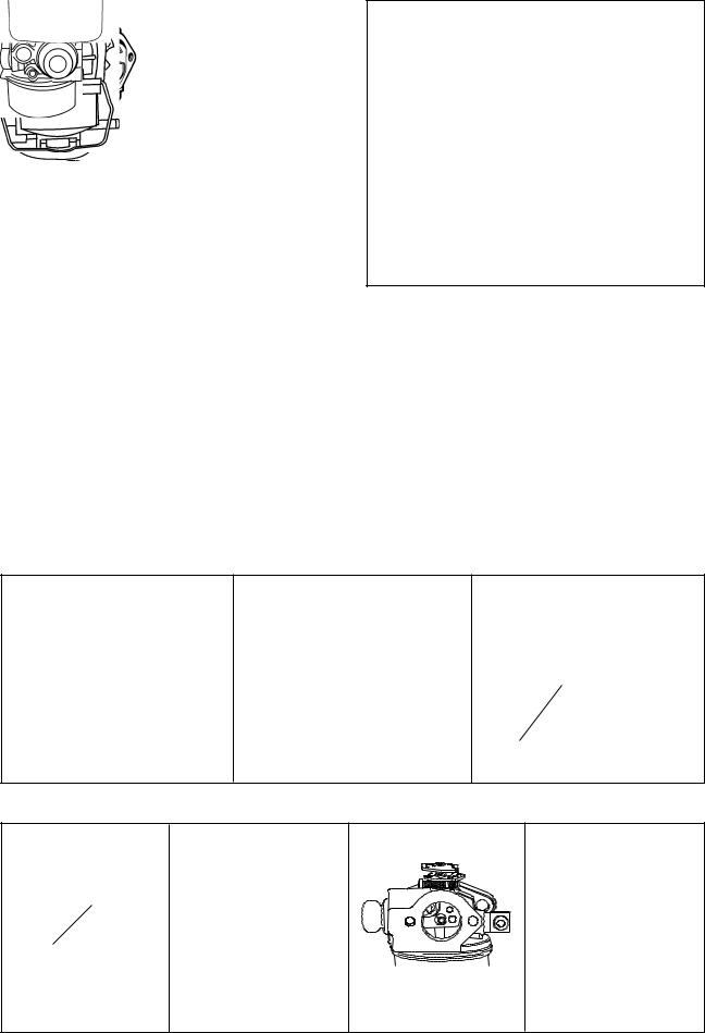
TECUMSEH CARBURETORS
DUAL SYSTEM / SERIES "6" |
SERIES "7" |
SERIES "3" & "4" |
|
|
|
|
|
|
MAIN |
|
|
|
|
|
IDLE MIXTURE |
|
MIXTURE |
|
NON-ADJUSTABLE |
|
FIXED HIGH AND LOW SPEED |
|
|
SCREW |
||
18 |
19 |
SCREW |
|
||||
PRIMER NO CHOKE |
20 |
||||||
MIXTURE |
|
||||||
WALBRO
CARBURETOR
SERIES "8" |
SERIES "9" |
CAPPED |
|
|
FIXED |
|
|
IDLE JET |
|
|
NON-ADJUSTABLE |
|
|
(ADJUSTABLE MAIN FOR |
21 |
NON-ADJUSTABLE |
EXPORT) |
SERIES "10" |
|
WALBRO LMK |
22 |
23 |
24 |
13
If further adjustment is required, the main adjustment should be made under a load condition.
If the engine stops or hesitates while engaging the load (lean), turn the main mixture adjusting screw out (counterclockwise) 1/8 turn at a time, testing each setting with the equipment under load, until this condition is corrected. A few Tecumseh carburetors were built as air adjust idle system. If you have one, the adjustments are reversed out for lean in for richer.
If the engine smokes excessively (rich), turn the main adjusting screw in (clockwise) 1/8 turn at a time, testing each setting with the equipment under load, until this condition is corrected.
After the main mixture screw is set, move the speed control to the IDLE or SLOW position. If the engine does not idle smoothly, turn the idle mixture screw 1/8 turn either in (clockwise) or out (counterclockwise) until engine idles smoothly.
Recheck the high and low R.P.M. setting and adjust as necessary.
CARBURETOR DISASSEMBLY PROCEDURE
NOTE : CARBURETORS THAT ARE EMISSION COMPLIANT (MANUFACTURING NUMBERS 5000 OR GREATER) WITH FIXED IDLE OR MAIN JETS ARE TO BE REMOVED BY DEALERS ONLY FOR INSPECTION AND CLEANING.
1.Note or mark the high and low mixture adjusting screws to aid in reassembly (if applicable). Remove the high speed mixture screw, bowl nut, and float bowl. Remove the idle mixture screw assembly. On Series 7 carburetors, release the wire retainer that retains the bowl and remove the bowl assembly. If a screwdriver or similar tool is used to release the retainer, carefully move the retainer to prevent bending of the wire.
2.Series 8 carburetors have a tamper resistant cap, over the fixed idle jet. (diag. 21). The cap is removed by piercing it with an ice pick or similar instrument, then remove the jet for service, always replace the cap.
3.Note the position of the spring clip on the inlet needle and float. Remove the float hinge pin with a needlenose pliers. Some carburetors use a float dampening spring to aid the inlet valve to maintain a steady position in rough service applications. Note the position of the hooks before removing the float hinge pin (diag. 25). On Series 7 carburetors, grasp the crossbrace on the float with a needlenose pliers and pull straight out to release the float hinge pin.
4.Remove the float, clip, and inlet needle.
5.Remove the inlet needle seat using a wire or a paper clip with a 3/32" (2.38 mm) hook end (Tecumseh carburetors only, Walbro model LMK uses a non-serviceable seat). Push the hook through the hole in the center of the seat and pull out to remove it.
6.On Series 7 only, remove the main nozzle tube, "O" ring, and spring located in the center leg of the carburetor bowl. Remove the bowl drain screw and gasket. Remove the spring, metering jet, and "O" ring.
7.Note or mark the action of the choke and throttle shutters and the hook points of the choke or throttle return spring or seal retainer springs located on the top of the choke or throttle shaft.
NOTE: MARK THE EDGES OF THE THROTTLE AND CHOKE SHUTTERS PRIOR TO DISASSEMBLY. THE SHUTTERS HAVE BEVELED EDGES AND MUST BE INSTALLED IN THE ORIGINAL POSITION.
Remove the throttle shutter, throttle shaft, choke shutter, springs and choke shaft by removing the screw or screws that attach the throttle or choke shutter to the shaft inside the air horn. To remove the choke shaft assembly on Series 7 or Walbro LMK carburetors, grasp the choke shutter with a pliers and pull it through the slot in the choke shaft. Slide the choke shaft out of the carburetor body.
|
|
|
|
|
|
|
3/32" |
|
|
|
|
|
|
|
|
|
|
|
(2.38 |
mm) |
|
LONG END |
|
|
|
|
|
CLIP |
|
|
|
|
|
|
|
|
|
|
|
|
|
||
|
|
|
|
|
OPEN END |
|
|
|
|
|
|
|
|
|
|
|
|
|
|
||
OF CLIP |
|
|
|
|
|
|
|
|
||
|
|
|
|
OF CLIP |
|
|
|
|
||
|
|
|
|
|
|
|
|
|
|
|
|
|
|
|
|
|
THROTTLE |
|
|
|
|
|
|
|
|
|
|
END |
|
|
|
|
CHOKE |
|
|
|
|
|
|
|
|
|
|
END |
25 |
26 |
27 |
|||||||
|
|
|||||||||
14
8.Remove the primer bulb (if equipped) by grasping with a pliers and pulling and twisting out of the body. Remove the retainer by prying and lifting out with a screwdriver. Do not reuse old bulb or retainer (diag. 28).
9.Remove all welch plugs if cleaning the carburetor. Secure the carburetor in a vise equipped with protective jaws. Use a small
chisel sharpened to a 1/8" (3.175 mm) wide wedge point. Drive the chisel into the plug to
pierce the metal and push down on the chisel 28 to pry the plug out of the hole (diag. 29).
NOTE: DO NOT REMOVE ANY BALL OR CUP PLUGS (diag. 29).
10.Note the direction of the inlet fitting. If necessary the inlet fitting can be removed by pulling with a pliers or vise, do not twist. The fitting must be replaced. Tap a 1/4-20 thread inside the metal shank, use 1/4"-20 bolt and nut inserted into a 1/4" (6.350 mm) flat washer and 1/2" (12.700 mm) nut, thread the bolt into the shank, and thread the nut down to pull out the shank.
11.The Walbro LMK carburetor main fuel jet can be removed only if the jet is damaged or if a high altitude jet is needed to be installed. To remove place the carburetor firmly in a soft jawed vice. Using a punch the same size or slightly smaller than the jet, drive the jet through and into the center leg. Insert the high altitude jet in the same hole. Using a punch slightly larger than the diameter of the new jet, tap it into place flush with the outside of the center leg casting (diag. 31).
SMALL |
|
|
|
|
DO NOT REMOVE PLUGS |
WALBRO LMK SERIES |
|
PIERCE PLUG |
|
ATMOSPHERIC |
|
||||
CHISEL |
|
|
|||||
|
WITH TIP |
|
BRASS OR BALL PLUG |
VENT |
|
||
PRY OUT |
|
|
|
||||
|
|
WELCH PLUG TO |
|
|
|
||
|
|
|
|
|
|||
PLUG |
|
|
|
|
|
||
|
|
BE REMOVED |
|
|
|
||
|
|
|
|
|
|
||
DO NOT ALLOW |
|
|
|
|
|
|
|
|
|
|
|
|
|
|
|
CHISEL POINT |
|
|
|
ABOUT 1/8" |
|
|
|
TO STRIKE |
|
|
|
(3.175 mm) |
|
|
|
CARBURETOR |
|
|
|
WIDE |
|
|
|
BODY OR |
|
|
|
|
BALL PLUG IDLE FUEL PASSAGE |
|
|
CHANNEL |
|
|
|
|
|
|
|
|
|
|
|
|
|
||
REDUCER |
SMALL CHISEL |
29 |
REDUCTION ROD INSIDE 30 |
HIGH SPEED JET |
31 |
||
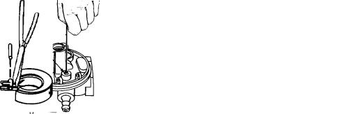
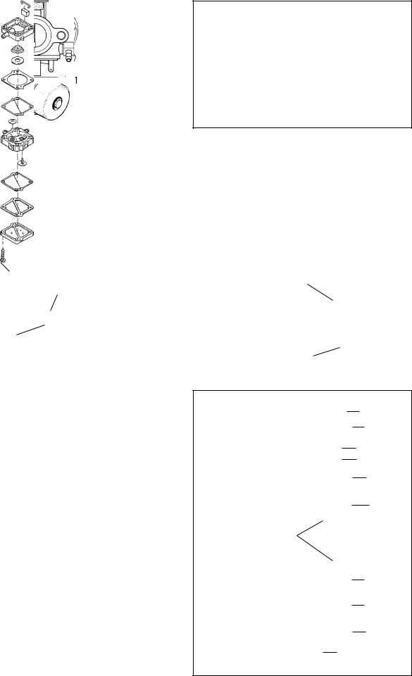
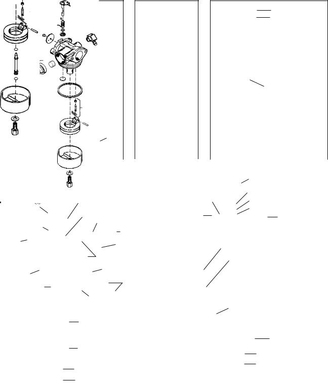
Impulse Fuel Pump
The valve type impulse pump can be serviced using the following procedure.
1.Remove the old filter on the back of the pump body if applicable.
2.Note or mark the pump body alignment, remove the four screws and disassemble the pump.
3.Remove the gaskets, diaphragms, old valves and spring bearing from the spring.
4.Clean the body parts with solvent.
5.Install new valves with the face of the valve facing the raised portion of the passage. After installation, cut off the extended portion of the valves.
6.Install the diaphragms against the center portion of the body with the gaskets against the outside covers. The parts can only can be assembled one way without damage.
7.Install the spring bearing on the new spring and place into position.
8.Assemble the body sections, install the retaining screws, and torque the screws to 12 - 16 inch pounds (1.36 - 1.81 Nm).
9.Install new filter in pump cavity if applicable.
|
|
11 |
|||
|
|
1 |
|||
|
|
10 |
|
||
|
|
4 |
|
||
|
|
7 |
|||
|
|
11 |
|||
|
5 |
|
|
2 |
|
|
|
||||
|
|
8 |
|||
1 |
- Body, Impluse |
6 |
|||
2 |
- Body, Pump |
||||
|
|
|
|||
3 |
- Cover, Pump |
|
|
|
|
4 |
- Bearing, Spring |
|
|
|
|
5 |
- *Valve, Check (2) |
3 |
|||
6 |
- *Gasket, Pump Cover |
|
|
|
|
7 |
- *Diaphragm, Pump (2) |
9 |
|
|
|
9 |
- Screw, 1-1/4" (4) |
|
|
||
10 - *Spring, Pressure |
|
11 - *Filter, Air |
32 |
|
15
FLOAT ADJUSTING PROCEDURE
All Tecumseh carburetors with an adjustable float require the correct float height to achieve the proper operation and easy engine starts. To check the float setting, hold the carburetor in an upside down position. Remove the bowl nut, float bowl, and "O" ring. Place an 11/64" (4.36mm) diameter drill bit across the top of the carburetor casting on the opposite side and parallel to the float hinge pin. The float must just touch the drill bit when the bit is flush with the edge of the float. If the float is too high or too low, adjust the height by bending the tab accordingly. If the required adjustment is minor, the tab adjustment may be made without removing the float and carefully inserting a small bladed screwdriver to bend the tab.
FLOAT
FLOAT HINGE AND AXLE
FLOAT SETTING
11 / 64" (4.36 mm)
ADJUSTING TAB |
INLET NEEDLE |
33 |
|
AND SEAT |
If float sticking occurs due to deposits, or when the fuel tank is filled for the first time, this condition can be quickly corrected by loosening the carburetor bowl nut one full turn. Turn the bowl 1/4 inch in either direction, then return the bowl to its original position and tighten the bowl nut.
THE TECUMSEH SERIES 7 AND THE WALBRO MODEL LMK CARBURETOR HAVE A FIXED AND NONADJUSTABLE FLOAT HEIGHT.
Inspection
After careful disassembly of the carburetor and the removal of all non metallic parts, all metallic parts should be cleaned with solvent, or commercial carburetor cleaner, no longer than 30 minutes. Wearing eye protection, use compressed air and soft tag wire or monofilament fishing line to clean internal carburetor passages. To perform a proper carburetor rebuild, the welch plugs must be removed to expose the drilled passages.
Throttle and Choke
Examine the throttle and choke shaft, and carburetor body at the bearing points and holes into which the linkage is fastened, and replace if worn or damaged. Any excessive wear in these areas can cause dirt to enter the engine and cause premature wear. If dust seals are present, check the seal condition and the correct placement next to the carburetor body.
Idle and High Speed Mixture Adjusting Screw
Examine the idle mixture needle tip and tapered surface for damage. The tip and tapered surface of the needle must not show any wear or damage. If either is worn or damaged, replace the adjusting needle. Tension is maintained on the screw with a coil spring. Replace the “O” ring seal if removed (diag. 34).
Examine the tapered surface of the high speed mixture needle. If the tapered surface is damaged or shows wear, replace the needle.
Fuel Bowl Retaining Nut
The bowl nut contains the passage through which fuel is delivered to the high speed and idle fuel system of the carburetor. If a problem occurs with the idle system of the carburetor, examine the small fuel passage in the annular groove in the bowl nut. This passage must be clean for the proper transfer of fuel into the idle metering system.
Bowl nuts that are used on adjustable main, float style carburetors may use either one or two metering ports. This difference relates to calibration changes of the carburetor, depending on the application (diag. 35).
NOTE: DO NOT INTERCHANGE BOWL NUTS.
The fuel inlet ports must be free of any debris to allow proper fuel flow.
"O" RING
RETAINER NUT
BRASS WASHER
SPRING
HIGH SPEED
ADJUSTMENT
SCREW
34
|
IDLE FUEL |
FUEL- |
FUEL- |
TRANSFER |
INLET |
METERING |
PASSAGE |
|
PORT |
|
ONE-HOLE TYPE TW0-HOLE TYPE |
35 |
|
16
Fuel Bowl, Float, Needle and Seat
NOTE: To prevent damage to the float bowl on Series 7 carburetor, pull straight up with a needle nose pliers in the pocket closest to the main fuel well (diag. 37).
The float bowl must be free of dirt and corrosion. Clean the bowl with solvent or carburetor cleaner (soak 30 minutes or less).
Examine the float for cracks or leaks. Check the float hinge bearing surfaces for wear, as well as the tab that contacts the inlet needle. Replace any damaged or worn parts.
The needle and seat should be replaced if any fuel delivery problems are experienced (flooding or starvation). Sealing problems with the inlet needle seat may not be visible and replacement is recommended. Only the inlet needle is serviceable on the Walbro model LMK carburetor.
FLOAT HINGE
PIN SEAT NEEDLE
NEEDLE & |
FLOAT |
|
|
|
|
|
|
|
|
|
|
|
|
|
|
|
|
|
|
SPRING CLIP |
|
||||||
|
|
|
|
|
|
|
|
|
|
|
|
|
|
|
|
|
|
|
|
|
|
||||||
SEAT |
MAIN NOZZLE |
|
|
|
|
|
|
|
|
|
|
|
|
|
|
|
|
|
|
|
|
HINGE PIN |
|
||||
|
|
|
|
|
|
|
|
|
|
|
|
|
|
|
|
|
|
|
|
|
|
|
|
||||
SEAT |
EMULSION |
|
|
|
|
|
|
|
|
|
|
|
|
|
|
|
|
|
|
|
|
|
|
||||
|
|
|
|
|
|
|
|
|
|
|
|
|
|
|
|
|
|
|
|
|
|
|
|
|
|||
RETAINING |
"O" RING |
|
|
|
|
|
|
|
|
|
|
|
|
|
|
|
"O" RING |
|
|||||||||
|
|
|
|
|
|
|
|
|
|
|
|
|
|
|
|
||||||||||||
RING |
POSITIONED IN |
|
|
|
|
|
|
|
|
|
|
|
|
|
|
|
|
|
|
|
|
|
|
||||
|
|
|
GROOVE |
|
|
|
|
|
|
|
|
|
|
|
|
|
|
NOZZLE |
|
||||||||
|
|
|
SPRING |
|
|
|
|
|
|
|
|
|
|
|
|
|
|
|
|||||||||
|
|
|
|
|
|
|
|
|
|
|
|
|
|
|
|
|
|
||||||||||
|
|
|
IDLE RESTRICTION |
|
|
|
|
|
|
|
|
|
|
|
|
|
|
|
|
|
|
|
|
|
|
||
|
|
|
BOWL |
|
|
|
|
|
|
|
|
|
|
|
|
|
|
"O" RING |
|
||||||||
|
|
|
|
|
|
|
|
|
|
|
|
|
|
|
|
|
|
||||||||||
|
|
|
|
|
|
|
|
|
|
|
|
|
|
|
|
|
POSITIONED IN |
|
|||||||||
|
|
|
|
|
|
|
|
|
|
|
|
|
|
|
|
|
|
|
|
|
|||||||
|
|
|
'O' RING |
|
|
|
|
|
|
|
|
|
|
|
|
|
|
GROOVE |
|
||||||||
|
|
|
|
|
|
|
|
|
|
|
|
|
|
|
|
|
|
|
|
|
|
|
|
|
|||
|
|
|
MAIN JET |
|
|
|
|
|
|
|
|
|
|
|
|
|
|
|
|
|
|
|
BOWL |
|
|||
|
|
|
|
|
|
|
|
|
|
|
|
|
|
|
|
|
|
|
|
|
|
|
|||||
|
|
|
MAIN JET |
|
|
|
|
|
|
|
|
|
|
|
|
|
|
|
|
|
|
|
|
|
|
||
|
|
|
SPRING |
|
|
|
|
|
|
|
|
|
|
|
|
|
|
|
|
|
|
|
|
|
|
||
|
|
|
GASKET |
|
|
|
|
|
|
|
|
|
|
|
|
|
|
|
|
|
|
WASHER |
|
||||
|
|
|
|
|
|
|
|
|
|
|
|
|
|
|
|
|
|
|
|
|
|
||||||
|
|
|
|
|
|
|
|
|
|
|
|
|
|
|
|
|
|
|
|
|
JET/BOWL NUT |
|
|||||
BOWL RETAINER |
BOWL DRAIN |
|
|
|
|
|
|
|
|
|
|
|
|
|
|
|
|
|
|
38 |
|||||||
|
|
|
|
|
|
|
|
|
|
|
|
|
|
|
|
|
|
||||||||||
|
|
|
|
|
|
|
|
|
|
|
|
|
|
|
|
|
|
|
|
|
|||||||
36 |
|
|
|
37 |
|
|
|
|
|
SERIES 8, 9 & 10 |
|||||||||||||||||
|
SERIES 7 |
|
|
|
|
|
|
|
|
||||||||||||||||||
|
|
|
|
|
|
|
|
|
|
|
|
|
|
|
|
|
|
|
|
|
|
|
|
|
|
||
|
|
|
|
|
|
|
|
|
|
|
|
|
|
|
|
|
|
|
|
|
|
|
|
|
|
|
|
CHOKE SHAFT |
|
|
|
|
|
|
|
|
|
|
THROTTLE SHAFT & LEVER |
||||||||||||||||
|
|
|
|
|
|
|
|
|
|
|
|
|
|
|
|
|
|
|
|
|
|
|
|
|
|||
|
|
|
THROTTLE SHAFT |
|
|
|
|
|
|
THROTTLE RETURN SPRING |
|||||||||||||||||
|
|
|
|
|
|
|
|
THROTTLE SHUTTER |
|
||||||||||||||||||
|
|
|
THROTTLE DUST SEAL |
|
|
|
|
DUST SEAL WASHER |
|
||||||||||||||||||
CHOKE DUST |
|
|
|
|
|
|
|
|
|||||||||||||||||||
|
|
|
|
|
|
|
|
|
|
DUST SEAL |
|
||||||||||||||||
SEAL |
THROTTLE RETURN SPRING |
|
THROTTLE |
|
|
|
|||||||||||||||||||||
|
|
|
|
|
|
|
|
|
|
|
|
|
|
|
|
|
|
FUEL FITTING |
|
||||||||
|
|
|
IDLE SPEED SCREW |
|
|
|
|
|
|
|
|
|
|
|
|
|
|
|
|
||||||||
CHOKE RETURN |
|
SHUTTER |
|
|
|
|
|
|
|
|
|
|
|
|
|
|
|
|
|
||||||||
|
|
|
|
|
|
|
|
|
|
|
|
|
|
|
|
|
|
|
|
|
|
||||||
SPRING |
WELCH PLUG |
|
SCREW |
|
|
|
|
|
|
|
|
|
|
|
|
|
|
|
|
|
|||||||
|
|
|
|
PRIMER BULB/ |
|
|
|
|
|
|
|
|
|
|
|
|
|
|
|
|
|
||||||
CHOKE |
|
|
|
|
|
|
|
|
|
|
|
|
|
|
|
|
|
|
|
|
|
|
|||||
IDLE MIXTURE |
|
RETAINER |
|
|
|
|
|
|
|
|
|
|
|
|
|
|
|
|
|
||||||||
SHUTTER |
|
|
|
|
|
|
|
|
|
|
|
|
|
|
|
|
|
|
|||||||||
SCREW |
|
|
RING |
|
|
|
|
|
|
|
|
|
|
|
|
|
|
|
|
|
|||||||
|
|
|
|
|
|
|
|
|
|
|
|
|
|
|
|
|
|
|
|
|
|
||||||
|
|
|
TENSION SPRING |
|
|
|
|
|
|
|
|
|
|
|
|
|
|
|
|
|
|
|
|
|
|
||
|
|
|
THROTTLE SHUTTER |
|
|
|
|
|
|
|
|
|
|
|
|
|
"O" RING |
|
|||||||||
FUEL FITTING |
|
|
|
|
|
PRIMER BULB |
|
|
|
|
|
|
|
|
|
|
|||||||||||
|
|
|
|
|
|
|
|
|
|
|
|
|
|
|
|||||||||||||
|
|
|
|
|
|
|
|
|
|
|
|
|
|
|
|
|
|
|
|
|
|
||||||
|
SCREW |
|
|
FILTER |
|
|
|
|
|
|
SEAT AND CLIP INLET |
|
|||||||||||||||
|
|
|
|
|
|
|
|
|
|
|
|
|
|||||||||||||||
INLET NEEDLE |
|
|
|
|
|
|
|
|
|
|
|
|
|
||||||||||||||
|
|
|
|
|
ATMOSPHERIC VENT |
|
|
|
|
|
|
NEEDLE |
|
||||||||||||||
|
|
|
|
|
|
|
|
|
|
|
|
||||||||||||||||
|
|
|
|
|
|
|
|
|
|
|
|
|
|
|
|
|
SPRING CLIP |
|
|||||||||
FLOAT |
|
|
FLOAT SHAFT |
|
|
WELCH PLUG |
|
|
|
|
|
|
|
|
|
|
|||||||||||
|
|
|
|
|
|
|
|
|
|
|
|
|
|
||||||||||||||
|
|
|
|
|
|
|
|
|
|
|
|
|
|
|
|
|
|
|
FLOAT SHAFT |
|
|||||||
|
|
|
|
|
|
|
FLOAT |
|
|
|
|
|
|
|
|
|
|
|
|
|
|||||||
|
|
|
|
|
|
|
|
|
|
|
|
|
|
|
|
|
|
|
|
|
|||||||
|
|
|
|
|
|
|
|
|
|
|
|
|
|
|
|
|
|
|
|
|
|
|
|
|
|||
|
|
|
"O" RING |
|
|
|
|
|
|
|
|
|
|
|
|
|
|
|
|
|
|
|
|
|
|
||
|
|
|
|
|
|
|
|
|
|
|
|
|
|
|
|
|
|
|
|
|
|
|
|
FLOAT BOWL |
|
||
|
|
|
FLOAT BOWL |
|
|
|
|
|
|
|
|
|
|
BOWL NUT WASHER |
|
||||||||||||
|
|
|
|
|
|
|
|
|
|
|
|
|
|
|
|
|
|||||||||||
|
|
|
BOWL NUT WASHER |
|
|
|
|
|
|
|
|
|
|
HIGH SPEED BOWL NUT |
|||||||||||||
|
|
|
|
|
|
|
|
|
|
|
|
|
|
|
|
|
|
|
|
|
|
|
|
|
|||
|
|
|
BOWL NUT |
|
|
|
|
|
|
|
|
|
|
|
|
|
|
|
|
|
|
|
|
|
|
||
|
|
WALBRO LMK |
39 |
|
|
|
|
SERIES 6 |
40 |
||||||||||||||||||
17
ASSEMBLY PROCEDURE |
|
|
|
|
|
|
|
Welch Plugs |
|
|
|
|
|
|
|
To install a new welch plug after cleaning the |
|
|
|
|
|
|
|
carburetor, secure the carburetor in a vise equipped |
|
|
|
|
|
|
|
with protective jaws. Place the welch plug into the |
|
|
|
|
FLAT END PUNCH |
||
receptacle with the raised portion up. With a punch |
|
|
|
|
|||
|
|
|
|
|
|
|
|
equal to the size of the plug hole, merely flatten the |
NEW WELCH PLUG |
|
|
|
SAME OR |
||
plug. Do not dent or drive the center of the plug below |
|
|
|
||||
|
|
|
|
|
|
LARGER |
|
the top surface of the carburetor. After installation of |
|
|
|
|
|
|
DIAMETER OF |
|
|
|
|
|
|
||
the welch plug, seal the outer diameter with fingernail |
|
|
|
|
|
|
PLUG HOLE |
polish (diag. 41). |
|
|
|
41 |
|||
|
|
|
|
|
|
|
|
Throttle Shaft and Plate |
|
|
|
|
|
|
|
When reassembling Tecumseh or Walbro carburetors, |
THROTTLE |
|
|
THROTTLE |
|||
PLATE |
|
|
LEVER |
||||
it is important that the lines, lettering, or numbers on |
|
|
|
|
|
|
TWELVE |
the throttle plate are facing out when in the closed |
|
|
|
|
|
|
O'CLOCK |
position. If the throttle plate has only one line, this |
|
|
|
|
|
|
POSITION |
line should be positioned in the 3 o’clock position on |
|
|
|
|
|
|
|
Series 3, 4, and 7 carburetors, and at the 12 o'clock |
|
|
|
|
|
|
|
position on Series 1, 6, 8, 9 carburetors. (diag. 42 & |
|
|
|
|
|
|
|
43). |
|
|
|
42 |
|||
Test the operation of the throttle and return spring if |
|
|
|
||||
|
|
|
|
|
|
|
|
equipped. If binding occurs, correct by loosening the |
|
|
|
|
|
|
THREE |
screws and repositioning throttle plate. |
|
|
|
|
|
|
|
|
|
|
|
|
|
|
O'CLOCK |
Always use a new screw(s) when reinstalling the |
|
|
|
|
|
|
POSITION |
throttle shutter to prevent the screws from loosening |
|
|
|
|
|
|
|
and being drawn into the engine. New Tecumseh |
|
|
|
|
|
|
|
screws are treated with dry-type adhesive to secure |
|
|
|
|
|
|
|
them in place. |
|
|
|
|
|
|
|
NOTE: NEVER REUSE OLD SCREWS. |
|
43 |
|
|
|
||
On Walbro LMK and Series 7 carburetors, install the |
|
DUST SEALS |
|
throttle return spring on the throttle shaft with the |
|
||
|
|
||
squared end up. Slide the foam dust seal over the |
|
|
|
spring. Insert the throttle lever assembly into the |
|
|
|
carburetor body with both tangs of the return spring |
|
|
|
on the left side of the center boss (viewed from throttle |
|
|
|
end) and the flat side of the shaft toward the carburetor |
|
|
|
mounting flange. Install the throttle shutter to the |
|
|
|
throttle shaft using notes or marks to place the shutter |
|
|
|
as originally found (Series 7 must have the line on the |
|
|
|
shutter at the 3 o'clock position) (diag. 44). |
|
|
|
Always use new throttle shutter screws when |
|
44 |
|
reinstalling. Install the screws so they are slightly |
SERIES 7 |
||
|
|||
loose. Apply light downward pressure on the throttle |
|
|
|
shaft and rotate it clockwise to seat the throttle shutter |
THROTTLE LEVER |
|
|
in the bore, then tighten the throttle shutter screws. |
|
||
|
|
||
Check for binding by rotating the throttle shaft. If |
THROTTLE |
|
|
necessary, adjust the throttle shutter by loosening and |
|
||
|
|
||
repositioning the shutter, then retighten the screws |
|
|
|
(diag. 45). |
|
|
WALBRO LMK SERIES |
45 |
18
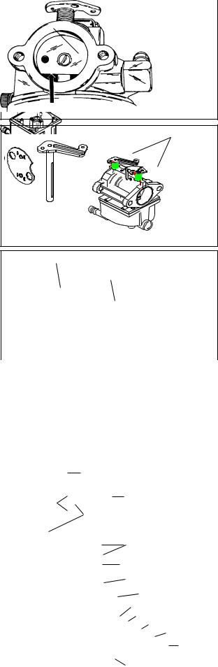
Choke Shaft and Plate |
|
|
|
The choke plate is inserted into the air horn of the |
CHOKE PLATE |
carburetor in such a position that the flat surface (if |
|
applicable) of the choke is down. Choke plates will |
|
operate in either direction. Make sure it is assembled |
|
properly for the engine. Test the operation of the choke |
|
and return spring function if equipped (diag. 46). |
|
Always use a new screw(s) when reinstalling the |
|
|
|
|
choke shutter as the screws are treated with dry-type |
|
|
|
|
adhesive to secure them in place. |
|
FLAT DOWN |
46 |
|
NOTE: NEVER REUSE OLD SCREWS. |
|
|||
|
|
|
||
The choke shaft and plate must be in the closed |
|
|
SPRING |
|
|
|
HOOKUPS |
||
position prior to tightening the screws. Hard starting |
|
|
||
|
|
|
||
may be due to insufficient choking action because of |
|
|
|
|
a misaligned choke plate. Correct by readjusting the |
Þ |
|
|
|
choke plate to close completely. Note the cutout |
|
|
||
|
|
|
||
position of choke shutter if applicable. |
|
|
|
|
On Walbro LMK and Series 7 carburetors, install the |
|
|
|
|
choke return spring on the choke shaft with the |
|
|
|
|
squared end up and hooked into the notch in the plate. |
|
|
|
|
Work the dust shield up around the spring and insert |
|
|
47 |
|
the choke shaft into the carburetor body. Rotate the |
|
|
||
|
|
|
||
shaft counterclockwise until the tang on the spring |
PRESS IN PARTIALLY |
SOME INLET FITTINGS |
||
rests against the left side of the center boss on the |
||||
THEN APPLY |
|
|
||
carburetor body (viewed from choke end) . Rotate the |
|
|
||
LOCTITE |
STRAINER |
|
||
choke shaft approximately 1/4 turn counterclockwise |
|
|
|
|
and insert the choke shutter into the slot in the choke |
|
|
|
|
shaft. Make sure the tabs on the shutter lock the choke |
|
|
|
|
shaft between them. Rotate the shaft and check for |
|
|
|
|
binding, the choke must return to the open position |
|
|
|
|
when released (diag. 47). |
|
|
|
|
Fuel Inlet Fitting |
|
|
48 |
|
|
|
|
||
When installing the fitting, insert the tip into the |
|
|
|
|
|
|
|
|
|
|
|
|
|
carburetor body. Support the carburetor body with a |
|
|
|
|
|
|
|
|
|
|
|
|
|
wood block to avoid damage to other parts. Use a |
|
|
RETAINER NUT |
|
|
|
|
|
"O" RING |
|
|||
|
|
|
|
|
|
|
|
||||||
bench vise or press to install the fitting squarely. Press |
|
|
|
|
|
|
|
|
|
|
BRASS WASHER |
|
|
it in until it bottoms out (diag. 48). |
|
|
|
|
|
|
|
|
|
|
|
SPRING |
|
High and Low Speed Adjusting Screw, Main |
|
|
|
|
|
|
|
|
|
|
|
|
|
|
|
|
|
|
|
|
|
|
|
|
|
|
|
Nozzle |
|
|
|
|
|
|
|
|
|
|
|
HIGH SPEED |
|
When reassembling, position the coil spring on the |
|
|
|
|
|
|
|
|
|
|
|
ADJUSTMENT |
49 |
|
|
|
|
|
|
|
|
|
|
|
|||
|
|
|
|
|
|
|
|
|
|
|
SCREW |
||
adjusting screws, followed by the small brass washer |
|
|
|
|
|
|
|
|
|
|
|
|
|
|
|
|
|
|
|
|
|
|
|
|
|
|
|
and the “O” ring seal. Turn the high speed adjustment |
|
|
|
|
|
|
|
|
|
|
|
|
|
|
|
|
|
|
|
|
|
|
|
|
|
|
|
screw into the bowl nut and the low speed mixture |
FLOAT HINGE PIN |
|
|
|
|
|
|
|
|
|
|
||
screw into the carburetor body (diag. 49). |
|
|
|
|
|
|
|
|
|
|
|
|
|
Some carburetors may have a fixed main mixture or |
NEEDLE & |
|
|
|
FLOAT |
|
|||||||
both a fixed idle mixture and main mixture, and are |
|
|
|
|
|
|
|
|
|
|
|||
SEAT |
|
|
|
|
|
|
|
|
|
|
|||
not adjustable. |
|
|
|
|
|
|
|
|
|
|
|
|
|
On Series 7carburetors, place the main nozzle spring |
SEAT RETAINING |
|
MAIN NOZZLE EMULSION |
||||||||||
|
|||||||||||||
|
|
|
|
|
|
|
|
|
|
||||
into the main nozzle cavity. Apply oil to the main nozzle |
RING |
|
|
|
"O" RING POSITIONED IN |
||||||||
"O" ring and push the main nozzle into the cavity |
|
|
|
|
|
|
GROOVE |
|
|||||
with the "O" ring end in first. |
|
|
|
|
SPRING |
|
|||||||
Next install the "O" ring in the main jet cavity. Place |
|
|
|
|
|
|
IDLE RESTRICTION |
|
|||||
the spring over the shoulder on the main jet and push |
|
|
|
|
|
|
|
|
|
|
|
BOWL |
|
the jet into the cavity with the main jet toward the "O" |
|
|
|
|
|
|
|
|
|
|
|
|
|
ring. Place a new gasket on the drain screw and |
|
|
|
|
|
|
|
"O" RING |
|
||||
tighten in position (diag. 50). |
|
|
|
|
|
|
|
|
|
MAIN JET |
|
||
On Walbro LMK carburetors, the main jet can be |
|
|
|
|
|
|
|
|
|
|
|
MAIN JET SPRING |
|
|
|
|
|
|
|
|
|
|
|
|
GASKET |
|
|
replaced by pressing it into the center leg of the |
|
|
|
|
|
|
|
|
|
|
|
BOWL |
|
carburetor until flush. (diag. 31 page 15). |
|
|
|
|
|
|
|
|
|
|
|
|
|
|
|
|
|
|
|
|
|
|
|
|
DRAIN |
||
|
|
|
|
|
|
|
|
|
|
|
|
||
NOTE: FOR HIGH ALTITUDE JETTING, CONSULT |
|
|
|
|
|
|
BOWL RETAINER |
50 |
|||||
BULLETIN 110. |
|
|
|
|
|
|
|
|
|
|
|
|
|
19
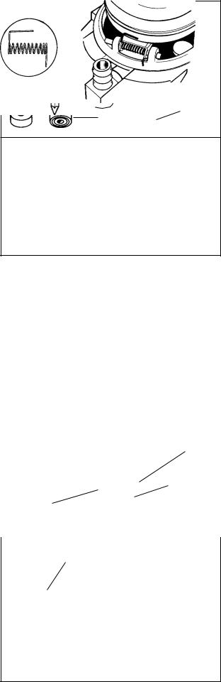
Inlet Needle and Seat
Make sure the seat cavity is clean. Moisten the seat with oil and insert the seat with the grooved side down and away from the inlet needle. Press the seat into the cavity using a 5/32" (3.969 mm) flat punch, making sure it is firmly seated (diag. 51). On Series "7" carburetors, install the seat retainer into the cavity and push it down using the flat punch until it contacts the seat.
The inlet needle hooks onto the float tab by means of a spring clip. To prevent binding, the long, straight end of the clip should face the choke or air filter end of the carburetor as shown (diag. 52).
Float Installation
On Series 7 carburetors, slide the hinge pin into the hinge on the float. Position the needle into the fuel inlet and snap the float pin into the tabs on the float bowl. Float height is not adjustable.
On Series 7 carburetors and the Walbro LMK, reinstall the inlet needle on to the float and place it into the carburetor (diag. 53).
1.When rebuilding a carburetor with a clip on the needle, position carburetor float side up for assembly.
2.Place the inlet needle and spring clip onto the float as shown. The long end of the spring clip must point towards the choke end of the carburetor. This will ensure that the inlet needle will move up and down in a straight line (diag. 53).
3.To set the proper float height on carburetors except Series 7 and Walbro LMK, see adjusting procedure.
4.Some Tecumseh float style carburetors have a damper spring which is installed as shown in diag. 55.
PUSH IN UNTIL
SEAT RESTS ON
BODY SHOULDER
IF YOUR CARBURETOR HAS A STEEL SEAT RETAINING RING RE-INTSALL AFTER SEAT INSTALLATION
INLET NEEDLE
SEATS AT THIS
POINT
5/32" (3.969 mm) FLAT PUNCH
SEAT
INSERT THIS
FACE FIRST
51
LONG END |
|
|
|
|
CLIP |
|
|
|
|
||
|
|
|
|
OPEN END OF CLIP |
|
OF CLIP |
|
||||
|
|
||||
Points toward choke |
|
|
|||
end |
|
THROTTLE |
|||
|
|
|
|
|
|
|
|
|
|
|
END |
CHOKE |
|
|
|||
END |
52 |
||||
|
|
|
|
||
SERIES 7 WALBRO / LMK |
53 |
|
|
|
CLIP |
|
OPEN END |
|
OF CLIP |
LONG END |
|
OF CLIP |
|
Points toward choke end |
54 |
|
|
|
|
POINTS TOWARD |
|
THE CHOKE END |
|
55
20
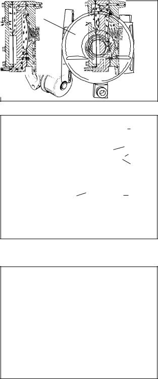
Fuel Bowl And Bowl Nut
Whenever a carburetor bowl is removed for service, the fuel bowl “O” ring (or gasket on Series "7") and the bowl nut washer must be replaced. For easier installation, lubricate the “O” ring with a small amount oil.
Installing the Float Bowl
Install the float bowl by placing the detent portion opposite of the hinge pin. Make sure the deepest end of the bowl is opposite of the inlet needle. The bowl has a small dimple located in the deepest part. The purpose of this dimple is to minimize the chances of the float sticking to the bottom of the bowl caused by stale fuel.
Impulse Fuel Pump
The diaphragms must be installed against the center body with the gaskets against the outside covers. The parts are designed so they cannot be misassembled without damage (diag. 57).
To test the unit, assemble the carburetor to the engine, leaving the fuel line from the pump off. Use a different fuel tank remotely placed above the carburetor to provide gravity fuel flow to the carburetor inlet to run the engine while testing the pump. Make sure fuel is available in both fuel tanks and the original fuel tank's fuel line is connected to the fuel pump inlet. Place the pump outlet line in a proper draining receptacle. With the pulse line connected from the engine crankcase to the pump and the engine running, a definite fuel flow should result at the pump outlet.
If the flow is erratic or intermittent, the pump needs repair or replacement.
Primer Bulb
To install, start the retainer and bulb into the casting with the retainer tabs pointed out. Firmly push the bulb and retainer into position using a 3/4'’ (19.05 mm) deep well socket (diag. 58).
Final Checks
Before reinstalling a newly overhauled carburetor, preset the main mixture adjustment screw, the idle mixture adjustment screw and the idle speed adjustment screw. See “Pre-sets and Adjustments” in this chapter.
DETENT
56
CARBURETOR
FITTING
VALVE CLOSED |
VALVE OPEN |
|
|
ATMOSPHERIC |
|
|
DIAPHRAGM |
|
|
VENT |
|
|
|
|
|
|
FILTER |
|
|
AIR BLEED |
VALVE OPEN |
VALVE CLOSED |
|
|
||
FUEL SUPPLY |
PULSE LINE |
|
|
|
TO CRANKCASE |
êCRANKCASE PRESSURE |
êCRANKCASE SUCTION AND |
áSUCTION FUEL FLOW DIRECTION |
áATMOSPHERIC PRESSURE ACTING |
FLOW DIRECTION |
ATMOSPHERIC PRESSURE |
ON DAMPING DIAPHRAGM |
ATMOSPHERIC PRESSURE |
êCAUSED FUEL FLOW |
áFUEL FLOW |
á ACTING ON DAMPING |
|
|
DIAPHRAGM |
|
|
|
57 |
58
21
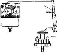
CHAPTER 4 GOVERNORS AND LINKAGE
GENERAL INFORMATION
Tecumseh 4 cycle engines are equipped with mechanical type governors. The governor’s function is to maintain a R.P.M. setting when engine loads are added or taken away. Mechanical type governors are driven off the engine’s camshaft gear. The governor follower arm rests on the center of the governor spool on center force governors, and off to one side on other governor systems. Changes in engine R.P.M. cause the governor lever to move the solid link that is connected from the governor lever to the throttle in the carburetor. The throttle is opened when the engine R.P.M. drops and is closed as an engine load is removed.
This chapter includes governor assembly linkage illustrations to aid in governor or speed control assembly.
OPERATION
As the speed of an engine increases, the governor |
|
SPRING |
|
weights on the governor gear move outward by |
|
|
|
centrifugal force. The shape of the governor weights |
THROTTLE |
|
|
force the governor spool to lift. The governor rod |
GOVERNOR SHAFT |
|
|
|
|
||
maintains contact with the governor spool due to the |
|
|
|
governor spring tension. The governor rod rotates |
|
|
|
causing the attached outer governor lever to push the |
|
|
|
solid link and close the throttle opening. When the |
|
WEIGHTS |
GOVERNOR |
engine speed decreases, the lower centrifugal force |
|
||
|
SPOOL |
||
|
|
||
allows the governor weights to be pulled in by the |
|
GOVERNOR GEAR |
|
governor spring. The governor rod rotates and the |
|
|
|
solid link moves the throttle to a more open position |
|
|
1 |
(diag. 1). |
|
|
|
|
|
|
|
TROUBLESHOOTING |
|
|
|
Engine operation problems where the governor is suspected to be the cause may actually be the result of other engine system failures. Hunting (engine R.P.M. surging up and down) indicates that the engine is incapable of maintaining a constant R.P.M. with or without an engine load. Engine overspeeding must be corrected immediately before serious engine damage occurs. Use the applicable following procedure to diagnose a suspected governor failure.
ENGINE OVERSPEEDING
1.If the engine runs wide open (faster than normal), shut the engine off or slow it down immediately.
2.Check the condition of the external governor shaft, linkage, governor spring, and speed control assembly for breakage or binding. Correct or replace binding or damaged parts.
3.Follow the governor adjustment procedure and reset the governor - see "Service" in this chapter.
4.Run the engine. Be ready to shut the engine off if an overspeed problem still exists. If the problem persists, the engine will require disassembly to inspect the governor gear assembly for damage, binding, or wear.
5.See Chapter 9 under "Disassembly Procedure" to disassemble the engine.
6.Remove the governor gear assembly. Repair or replace as necessary.
ENGINE SURGING
1.Try to stabilize the engine R.P.M. by holding in one position the solid link between the governor arm and the carburetor throttle, using a pliers or fingers.
2.If the engine R.P.M. stabilizes, the governor or governor adjustment should be checked. See "Service" governor adjustment procedure in this chapter. If the engine R.P.M. does not stabilize, the engine will require additional checks see Chapter 9 under "Troubleshooting".
3.If the problem persists after the governor adjustment, check the engine R.P.M. found on microfiche card # 30. The R.P.M. settings are critical. If the R.P.M. setting for high and low speed are within specification and a slight surge is experienced, increasing the engine idle R.P.M. setting slightly may eliminate this condition.
4.Check the governor shaft or linkages for binding, wear, or improper hookup. Check the governor spring for adequate tension or damaged condition. Repair or replace as necessary.
22
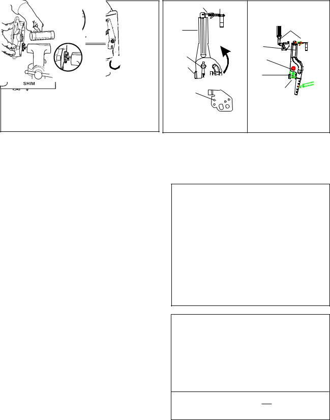
SERVICE
GOVERNOR ADJUSTMENT
With the engine stopped, loosen the screw holding the governor lever to the governor shaft clamp. Push the governor lever to move the carburetor throttle plate to the wide open position. Rotate the governor clamp counterclockwise on all overhead valve engines covered in this manual. Hold the lever and clamp in this position while tightening the screw (diag. 2).
PUSH
LEVER TO
WIDE OPEN
THROTTLE
Ý
GOVERNOR  CLAMP
CLAMP
SCREW
Ú
TURN CLIP COUNTERCLOCKWISE ON ALL VERTICAL |
|
SHAFT ENGINES EXCEPT VLV & VLXL. CLOCKWISE |
|
ON ALL HORIZONTAL SHAFT ENGINES EXCEPT |
|
OHH,OHSK 50,55 & OHM, OHSK 110,120. |
2 |
|
THROTTLE LINK |
THROTTLE PLATE |
THROTTLE OPEN |
|
|
|
(PUSH COUNTERCLOCKWISE) |
|
GOVERNOR |
|
STANDARD |
|
|
LOCATION |
|
|
LEVER |
THROTTLE OPEN |
|
|
|
|
||
|
(PUSH COUNTER- |
GOVERNOR |
|
|
CLOCKWISE) |
|
|
GOVERNOR |
|
LEVER |
|
|
|
|
|
ROD |
|
GOVERNOR |
|
GOVERNOR |
|
SCREW |
|
|
|
|
|
CLAMP |
|
GOVERNOR |
|
SCREW |
|
ROD |
|
|
|
|
|
YOU MUST USE THIS |
|
GOVERNOR |
|
LINK POSITION |
|
CLAMP |
|
|
|
|
|
ROTATE LEVER |
|
ROTATE CLAMP |
|
& ROD |
THROTTLE |
COUNTERCLOCKWISE |
|
COUNTER- |
|
|
|
CLOCKWISE |
PLATE |
|
|
|
(TOP VIEW) |
|
3 |
OHH SERIES - NEW STYLE |
OHH SERIES - OLD STYLE |
||
GOVERNOR GEAR AND SHAFT SERVICE
After the cylinder cover is removed from the engine, the governor spool, gear, or governor shaft can be removed. On some governor assemblies, the retaining ring must be removed to allow the spool or gear to slide off the shaft. Other governor shafts use an upset to hold the governor spool on. If the gear requires replacement, the governor shaft will have to be removed.
Governor Gear or Shaft Replacement, Upset Style Governor Shaft
1.Grip the original spool in a vise and use a twisting and pulling motion on the flange until the spool is free.
2.Clamp the shaft in a vise and pound gently on the flange with a wooden or plastic mallet to remove the shaft (diag. 4).
NOTE: DO NOT TWIST THE SHAFT WHEN
REMOVING. THE SHAFT BOSS MAY
BECOME ENLARGED AND THE PRESS FIT WILL NOT SECURE THE NEW GOVERNOR
SHAFT.
3.To install a new shaft, first assemble the gear and washer on the shaft. Start the shaft into the hole with a few taps from a soft faced hammer.
4.Place the flange in a press with a solid piece supporting the area below the shaft boss. Press the shaft in until a part # 670297
(.0125" / .3175 mm) shim just becomes snug
(.010" - .020" / .254-.508 mm clearance) (diag. 5).
4
GEAR
SHIM
WASHER
SHAFT BOSS
5
670297 (modified)
23
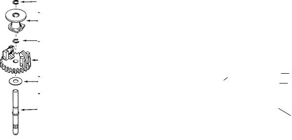
Governor Shaft Replacement, Retaining Ring Style
1.Remove the retaining ring, spool, gear assembly, and washer(s).
2.Clamp the shaft in a vise and pound gently on the flange with a wooden or plastic mallet to remove the shaft.
NOTE: DO NOT TWIST THE GOVERNOR SHAFT WHEN REMOVING. THE SHAFT BOSS MAY
BECOME ENLARGED AND THE PRESS FIT WILL NOT SECURE THE NEW GOVERNOR SHAFT.
3.Start the new shaft into the shaft boss by tapping with a soft faced hammer.
4.Refer to the chart at right for the proper shaft exposed length from the mounting surface. Add a drop of red Loctite 271 and press the governor shaft to the proper depth using a press or a vise. Wipe the extra Loctite off after installation.
5.Reassemble the washer (s), governor gear, and spool followed by the retaining ring.
ENGINE MODEL |
EXPOSED SHAFT LENGTH |
OHH/OHSK50-70 |
1.319" - 1.334" |
OVRM |
(33.502 - 33.883 mm) |
|
|
OHM |
1.085" - 1.100" |
OHSK80-130 |
(27.559 - 27.940 mm) |
OVM |
|
OVXL |
1.350" - 1.365" |
OHV |
(34.290-34.671 mm) 6 |
|
|
RETAINING |
SERVICED AS ASSEMBLY |
|
|
|
|
|
|
|
|
|
|
|
|
|
|
||||
|
|
|
|
RETAINING |
|
|
|
|
|
|
|
|
|
|
|
|
|
||
RING |
|
|
|
|
|
|
|
|
|
|
|
|
|
|
|
|
|
|
|
|
|
|
|
|
|
RING |
|
|
|
|
|
|
|
|
|
|
|
|
|
SPOOL |
|
|
|
SPOOL |
SPOOL |
|
|
|
|
|
SPOOL |
|
|
|
|
|
|
SPOOL |
|
|
|
|
|
|
|
|
|
|
|
|
|
|
|
||||||
|
|
|
|
|
|
|
|
|
|
|
|
|
|
|
|
||||
|
|
|
|
UPSET |
|
|
|
|
|
|
|
|
|
|
|
|
|
WASHER |
|
|
|
|
|
|
|
|
|
|
|
|
|
|
|
|
|
|
|
||
RETAINING |
|
|
|
WASHER |
|
|
|
|
|
|
|
|
|
|
|
|
RETAINING |
||
|
|
|
|
|
|
|
|
|
|
|
|
|
|
|
|||||
|
|
|
|
|
|
|
|
|
|
|
|
|
|
|
|
||||
|
|
|
|
RETAINING |
|
|
|
|
|
|
|
|
|
|
|
|
RING |
||
RING |
|
|
|
|
|
|
|
|
|
|
|
|
|
|
|
|
|
||
|
|
|
|
|
|
|
|
|
|
|
|
|
|
|
|
|
|
||
|
|
|
|
SHAFT |
|
RING |
|
|
|
|
|
|
|
|
|
|
|
|
GEAR ASSY. |
|
|
|
|
|
GEAR ASSY. |
|
|
|
|
SHAFT |
|
|
|
|
|
|
|||
GEAR ASSY. |
|
|
|
|
|
|
|
|
|
|
|
|
|
|
|||||
|
|
|
|
|
|
|
|
|
|
|
|
|
|
|
|||||
|
|
|
|
|
|
|
|
|
|
|
|
|
|
(GOV.) |
|||||
|
|
|
|
|
|
|
|
|
|
|
|
|
|
||||||
(GOV.) |
|
|
|
|
(GOV.) |
|
|
|
|
|
|
|
|
|
|
|
|
||
|
|
|
|
|
|
|
|
|
|
|
|
|
|
|
|
|
|||
|
|
|
|
|
|
WASHER |
|
|
|
|
GEAR ASSY. |
|
|
|
|
|
|
WASHER |
|
|
|
|
|
|
|
|
|
|
|
|
|
|
|
|
|
|
|||
WASHER |
|
|
|
|
|
|
|
|
(GOV.) |
|
|
|
|
|
SPACER |
||||
|
GEAR ASSY. |
SPACER |
|
|
|
|
|
|
|
|
|
||||||||
|
|
|
|
|
|
|
|
|
|
|
|
NOTE; SPACER |
|||||||
|
|
|
|
(GOV.) |
|
|
|
|
|
|
|
|
|
||||||
|
|
|
|
|
|
|
|
|
|
|
|
|
|
|
|
MAY BE PART |
|||
|
|
|
|
|
|
|
|
|
|
WASHER |
|
|
|
OF THE GEAR |
|||||
|
|
|
|
WASHER |
|
|
|
|
|
|
|
ASSEMBLY. |
|||||||
|
|
|
|
|
|
|
|
|
|
|
|
|
|
||||||
SHAFT |
|
|
|
|
|
SHAFT |
|
|
|
|
|
|
|
|
|
|
|
|
|
|
|
|
|
|
|
|
|
|
|
|
|
|
|
|
|
|
|
SHAFT |
|
|
|
|
|
|
|
|
|
|
|
|
|
|
|
|
|
|
|
|
|
|
7 |
|
|
|
8 |
MEDIUM FRAME 9 |
|
|
|
|
|
|
OVM / OHV / OHM |
||||||
OVRM TYPE I |
OVRM TYPE II |
OHH / OHSK50-70 10 |
OHSK80-130 11 |
||||||||||||||||
|
|
|
|
|
|
|
|
|
|
|
|
|
|
|
|
|
|
|
|
24
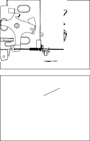
Speed Controls And Linkage
Many different types of speed controls and linkage are used for O.E.M. applications. Linkage attachment points are best recorded or marked prior to disassembly. This assures the correct placement during reassembly.
The solid link is always connected from the outermost hole in the governor lever to the throttle in the carburetor.
The governor spring is connected between the speed control lever and the governor lever. Vertical shaft engines may use an adjustable intake pipe mounted speed control bracket located above the carburetor, or a vertical or horizontal control mounted on the side of the engine. The ignition ground out terminal, idle R.P.M. and high speed R.P.M. adjustment screws may be located on the speed control bracket.
The adjustable speed control bracket which is mounted on the intake pipe must be aligned properly when installing. To align the control bracket, use the following steps.
1.Loosen the two screws on the top of the panel.
2.Move the control lever to full wide open throttle position and install a wire or aligning pin through the hole in the top of the panel, the hole in the choke actuating lever, and the hole in the choke
(diag. 12).
3.With the components aligned, tighten the two screws on the control panel.
The following pages show common linkage hookup arrangements. Whenever the carburetor or the governor linkage is removed or replaced, the engine R.P.M.'s should also be checked. Use microfiche card
#30 or contact a local Tecumseh dealer for the correct
R.P.M. settings for the engine model and specification.
NOTE: RPM SETTINGS CAN ALSO BE FOUND ON
THE COMPUTERIZED PARTS LOOK UP SYSTEMS.
OHH REMOTE SPEED CONTROL
The engine and equipment control must be adjusted to allow the engine control lever to touch the high speed stop when the equipment control is set in the
"highspeed" or "fast" position. Loosen the bowden wire clamp, place the equipment control to the "fast" position, move the engine control lever to contact the high speed stop, and hold the lever in this position while tightening the bowden wire clamp.
12
HIGH SPEED STOP
13
OHH GOVERNED IDLE SPEED CONTROL
This control is adjusted by bending the tabs on the control bracket to achieve the correct idle speed and high speed. When the engine is running, the governor controls both the idle and the high engine speed. In order for the governor to respond properly to a crankshaft load at engine idle, the idle speed screw on the top of the carburetor must be set 600 RPM lower than the governed idle speed. Use the following procedure to set the engine speeds (diag. 14 & 16).
1.Check to find the correct engine speeds found on microfiche card # 30 or using the Computer Parts Lookup System.
2.Start and allow the engine to run ( 3-5 minutes) before beginning adjustments. Place the control knob in the lowest engine speed position. Use a Vibra-Tach or other tachometer to set the non-governed idle speed (600 RPM lower than the governed idle speed) by pushing the bottom of the governor lever away from the control bracket so the throttle lever contacts the idle speed screw and hold the lever in this position. Turn the idle speed screw clockwise to increase or counterclockwise to decrease engine idle speed.
3.Allow the governor to control the throttle. Use a Vibra-Tach or other tachometer and bend the tab as shown to achieve the specified governed idle speed.
4.Slide the control knob to the high speed position and bend the tab as shown to achieve the specified
governed high engine speed.
25

NOTE: Early production OHH engines did not have governed idle, set only the idle crack screw and high speed governor stop.
|
WINTER |
|
|
APPLICATION |
|
|
CONTROL |
|
|
GOVERNED |
|
|
IDLE LINK |
|
|
AND |
|
|
ADJUSTMENT |
|
HIGH SPEED |
|
|
ADJUSTMENT |
BEND TO ADJUST SPEED |
|
|
|
|
|
DECREASE ÞÞ INCREASE |
14 |
OHH REMOTE & MANUAL |
||
GOVERNOR SPRING |
GOVERNED IDLE LINK |
|
OHH RV CONTROL |
16 |
THROTTLE CRACK SCREW |
T-10 |
|
|
|
GOVERNED |
|
|
HIGH SPEED |
|
|
ADJUST |
GOVERNED IDLE SCREW |
|
|
OHSK / OHM CONTROL |
18 |
|
NOTE: ON REMOTE |
HIGH SPEED ADJUST |
CONTROL THIS |
LOW SPEED ADJUST |
WILL NOT |
|
BE PRESENT |
|
HIGH SPEED ADJUST |
|
OHH FIXED SPEED |
|
15 |
THROTTLE CRACK SCREW |
T-10 |
||
|
|
|
GOVERNED |
|
|
|
HIGH SPEED |
|
|
|
ADJUST |
Þ |
BEND |
|
|
|
|
|
|
CORRECT BUSHING |
INCREASE ÞÞ DECREASE |
|
|
|
|
|
|
INSTALLATION DEEP |
|
|
|
SIDE |
GOVERNED IDLE TAB |
|
|
HERE |
|
|
|
|
|
|
|
|
OH / OHSK CONTROL |
17 |
|
LOW SPEED TAB |
HIGH SPEED TAB |
HIGH
PIN
Þ
OVRM SNAP IN CONTROL |
19 |
OVRM |
20 |
OVRM |
21 |
26
 Loading...