


TECOR F1251T, F1250T, F0500T, B6002AD, B3204UC Datasheet
...Data Book
and Design Guide
TECCOR ELECTRONICS
1800 Hurd Drive
Irving, Texas 75038
United States of America
Phone: +1 972-580-7777
Fax: +1 972-550-1309
Web site: http://www.teccor.com
E-mail: sidactor.techsales@teccor.com
An Invensys company


Teccor Electronics is the proprietor of the SIDACtor®, Battrax®, and TeleLink® trademarks. All other brand names may be trademarks of their respective companies. Teccor Electronics SIDACtor products are covered by these and other U.S. Patents:
4,685,120
4,827,497
4,905,119
5,479,031
5,516,705
All SIDACtor products are recognized and listed under UL file E133083 as a UL 497B compliant device. All TeleLink fuses are recognized under UL file E191008 and are also listed for CSA marking by certificate LR 702828.
IS
O
9
001
T
E
C
C
O
R
E
|
|
S |
|
IC |
|
ON |
|
|
LECTR |
|
|
Teccor Electronics reserves the right to make changes at any time in order to improve designs and to supply the best products possible. The information in this catalog has been carefully checked and is believed to be accurate and reliable; however, no liability of any type shall be incurred by Teccor for the use of the circuits or devices described in this publication. Furthermore, no license of any patent rights is implied or given to any purchaser.

NOTES

|
|
|
|
ProductSelection |
Guide |
|
1 |
Product Selection |
|
||
|
|
|
|
||
|
|
Guide |
|
|
|
|
|
|
|
|
|
|
|
|
|
|
Product Description . . . . . . . . . . . . . . . . . . . . . . . . . . . . . . . . . . . . . . . . . . . . . . . . . 1-2
Product Packages . . . . . . . . . . . . . . . . . . . . . . . . . . . . . . . . . . . . . . . . . . . . . . . . . . 1-4
Part Number Index . . . . . . . . . . . . . . . . . . . . . . . . . . . . . . . . . . . . . . . . . . . . . . . . . . 1-6
Description of Part Number . . . . . . . . . . . . . . . . . . . . . . . . . . . . . . . . . . . . . . . . . . . 1-8
Electrical Parameters . . . . . . . . . . . . . . . . . . . . . . . . . . . . . . . . . . . . . . . . . . . . . . . 1-10
Quality and Reliability . . . . . . . . . . . . . . . . . . . . . . . . . . . . . . . . . . . . . . . . . . . . . . . .1-11
Standard Terms and Conditions . . . . . . . . . . . . . . . . . . . . . . . . . . . . . . . . . . . . . . . 1-12
© 2002 Teccor Electronics |
1-1 |
http://www.teccor.com |
SIDACtor® Data Book and Design Guide |
|
+1 972-580-7777 |
Product Description
Product Description
SIDACtor components are solid state crowbar devices designed to protect telecom equipment during hazardous transient conditions. Capitalizing on the latest in thyristor advancements, Teccor makes SIDACtor devices with a patented ion implant technology. This technology ensures effective protection within nanoseconds, up to 5000 A surge current ratings, and simple solutions for regulatory requirements such as GR 1089, TIA-968 (formerly known as FCC Part 68), ITU-T K.20, ITU-T K.21, and UL 60950.
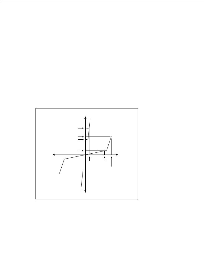
Operation
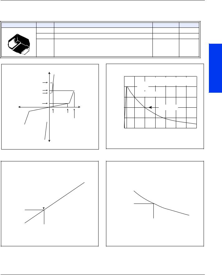
In the standby mode, SIDACtor devices exhibit a high off-state impedance, eliminating excessive leakage currents and appearing transparent to the circuits they protect. Upon application of a voltage exceeding the switching voltage (VS), SIDACtor devices crowbar and simulate a short circuit condition until the current flowing through the device is either interrupted or drops below the SIDACtor device’s holding current (IH). Once this occurs, SIDACtor devices reset and return to their high off-state impedance.
+I |
|
IT |
|
IS |
|
IH |
|
IDRM |
|
-V |
+V |
VT |
VDRM |
|
VS |
-I |
|
V-I Characteristics |
|
Advantages
Compared to surge suppression using other technologies, SIDACtor devices offer absolute surge protection regardless of the surge current available and the rate of applied voltage (dv/dt). SIDACtor devices:
•Cannot be damaged by voltage
•Eliminate hysteresis and heat dissipation typically found with clamping devices
•Eliminate voltage overshoot caused by fast-rising transients
•Are non-degenerative
•Will not fatigue
•Have low capacitance, making them ideal for high-speed transmission equipment
http://www.teccor.com |
1 - 2 |
© 2002 Teccor Electronics |
+1 972-580-7777 |
|
SIDACtor® Data Book and Design Guide |

Product Description
Applications
When protecting telecommunication circuits, SIDACtor devices are connected across Tip and Ring for metallic protection and across Tip and Ground and Ring and Ground for longitudinal protection. They typically are placed behind some type of current-limiting device, such as Teccor’s F1250T Telelink slow blow fuse. Common applications include:
•Central office line cards (SLICs)
•T-1/E-1, ISDN, and xDSL transmission equipment
•Customer Premises Equipment (CPE) such as phones, modems, and caller ID adjunct boxes
•PBXs, KSUs, and other switches
•Primary protection including main distribution frames, five-pin modules, building entrance equipment, and station protection modules
•Data lines and security systems
•CATV line amplifiers and power inserters
•Sprinkler systems
For more information regarding specific applications, design requirements, or surge suppression, please contact Teccor Electronics directly at +1 972-580-7777 or through our local area representative. Access Teccor’s web site at http://www.teccor.com or
e-mail us at sidactor.techsales@teccor.com.
Guide
Product Selection
© 2002 Teccor Electronics |
1 - 3 |
http://www.teccor.com |
SIDACtor® Data Book and Design Guide |
|
+1 972-580-7777 |

Product Packages
Product Packages
Surface Mount Packages
|
Modified |
Modified |
Surface Mount |
||||
DO-214AA |
DO-214AA |
MS-013 Six-pin |
|
|
(Fuse) |
||
|
|
|
|
|
|
|
|
|
|
|
|
|
|
|
|
|
|
|
|
|
|
|
|
Balanced SIDACtor Device |
|
|
|
Battrax Dual Negative SLIC Protector |
|
|
|
Battrax Dual Positive/Negative SLIC |
|
|
|
Protector |
|
|
|
Battrax Quad Negative SLIC Protector |
|
|
|
Battrax SLIC Protector |
|
|
|
CATV/HFC SIDACtor Device |
|
|
|
CATV Line Amplifiers/Power Inserters |
|
|
|
SIDACtor Device |
|
|
|
Fixed Voltage SLIC Protector |
|
|
|
Four-port Metallic Line Protector |
|
|
|
High Surge (D-rated) SIDACtor Device |
|
|
|
LCAS Asymmetrical Device |
|
|
|
Longitudinal Protector |
|
|
|
MC Balanced SIDACtor Device |
|
|
|
MC SIDACtor Device |
|
|
|
Multiport Balanced SIDACtor Device |
|
|
|
Multiport Quad SLIC Protector |
|
|
|
Multiport SIDACtor Device |
|
|
|
SIDACtor Device |
|
|
|
TeleLink Fuse |
|
|
|
Twin SLIC Protector |
|
|
|
http://www.teccor.com |
1 - 4 |
© 2002 Teccor Electronics |
+1 972-580-7777 |
|
SIDACtor® Data Book and Design Guide |
Product Packages
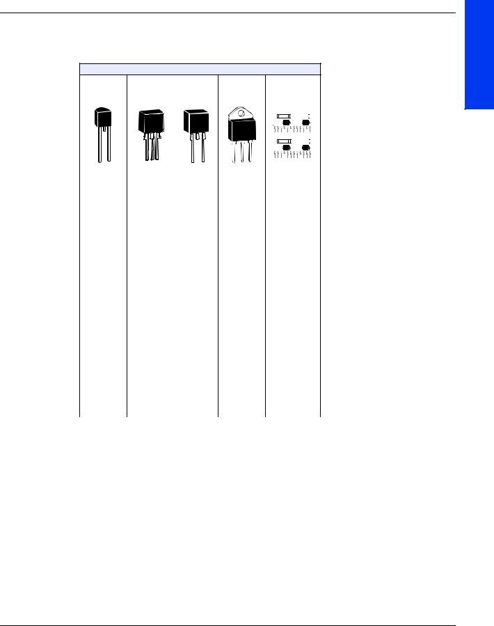
Through-hole Packages
|
Modified |
|
|
TO-92 |
TO-220 |
TO-218 |
Hybrid SIP |
|
|
|
|
|
|
|
|
|
|
|
|
|
|
|
|
|
|
|
|
|
|
|
|
|
|
|
|
|
|
|
|
|
|
|
|
|
|
|
|
|
|
|
|
|
|
|
|
|
|
|
|
|
|
|
|
|
|
|
|
|
|
|
|
|
|
|
|
|
|
|
|
|
|
|
|
|
|
|
|
|
|
|
|
Balanced SIDACtor Device |
|||
|
|
|
|
|
|
|
|
|
|
Battrax Dual Negative SLIC Protector |
|
|
|
|
|
|
|
|
|
|
Battrax Dual Positive/Negative SLIC |
|
|
|
|
|
|
|
|
|
|
Protector |
|
|
|
|
|
|
|
|
|
|
Battrax Quad Negative SLIC Protector |
|
|
|
|
|
|
|
|
|
|
Battrax SLIC Protector |
|
|
|
|
CATV/HFC SIDACtor Device |
||||||
|
|
|
|
CATV Line Amplifiers/Power Inserters |
||||||
|
|
|
|
|
|
|
|
|
|
SIDACtor Device |
|
|
|
|
|
|
|
|
|
|
Fixed Voltage SLIC Protector |
|
|
|
|
|
|
|
Four-port Metallic Line Protector |
|||
|
|
|
|
|
|
|
|
|
|
High Surge (D-rated) SIDACtor Device |
|
|
|
|
|
|
|
|
|
|
LCAS Asymmetrical Device |
|
|
|
|
|
|
|
Longitudinal Protector |
|||
|
|
|
|
|
|
|
MC Balanced SIDACtor Device |
|||
|
|
|
|
|
|
|
MC SIDACtor Device |
|||
|
|
|
|
|
|
|
Multiport Balanced SIDACtor Device |
|||
|
|
|
|
|
|
|
|
|
|
Multiport Quad SLIC Protector |
|
|
|
|
|
|
|
Multiport SIDACtor Device |
|||
|
|
|
|
|
|
|
SIDACtor Device |
|||
|
|
|
|
|
|
|
TeleLink Fuse |
|||
|
|
|
|
|
|
|
|
|
|
Twin SLIC Protector |
Guide
Product Selection
© 2002 Teccor Electronics |
1 - 5 |
http://www.teccor.com |
SIDACtor® Data Book and Design Guide |
|
+1 972-580-7777 |

Part Number Index
Part Number Index
Note: For explanation of part numbers, see "Description of Part Number" on page 1-8.
|
|
|
|
|
Part Number |
Page |
|
|
|
|
|
|
A1220U_4 |
2-36 |
|
|
|
|
|
|
A1225U_4 |
2-36 |
|
|
A2106A_ |
2-32 |
|
|
A2106U_ |
2-20 |
|
|
A2106U_6 |
2-24 |
|
|
A2106Z_ |
2-40 |
|
|
|
|
|
|
A5030A_ |
2-32 |
|
|
|
|
|
|
A5030U_ |
2-20 |
|
|
|
|
|
|
A5030U_6 |
2-24 |
|
|
A5030Z_ |
2-40 |
|
|
B1100C_ |
2-52 |
|
|
B1101U_ |
2-54 |
|
|
B1101U_4 |
2-58 |
|
|
|
|
|
|
B1160C_ |
2-52 |
|
|
|
|
|
|
B1161U_ |
2-54 |
|
|
B1161U_4 |
2-58 |
|
|
B1200C_ |
2-52 |
|
|
B1201U_ |
2-54 |
|
|
B1201U_4 |
2-58 |
|
|
B2050C_ |
2-52 |
|
|
|
|
|
|
B3104U_ |
2-56 |
|
|
|
|
|
|
B3164U_ |
2-56 |
|
|
B3204U_ |
2-56 |
|
|
F0500T |
2-66 |
|
|
F1250T |
2-66 |
|
|
F1251T |
2-66 |
|
|
P0080E_ |
2-16 |
|
|
|
|
|
|
P0080S_ |
2-4 |
|
|
P0080SA MC |
2-8 |
|
|
|
|
|
|
P0080SC MC |
2-6 |
|
|
P0080SD |
2-10 |
|
|
P0080Z_ |
2-44 |
|
|
P0084U_ |
2-22 |
|
|
|
|
|
|
P0300E_ |
2-16 |
|
|
P0300S_ |
2-4 |
|
|
|
|
|
|
P0300SA MC |
2-8 |
|
|
|
|
|
|
P0300SC MC |
2-6 |
|
|
P0300SD |
2-10 |
|
|
P0300Z_ |
2-44 |
|
|
P0304U_ |
2-22 |
|
|
|
|
|
|
Part Number |
Page |
|
|
|
|
|
|
P0602A_ |
2-28 |
|
|
|
|
|
|
P0602AC MC |
2-30 |
|
|
|
|
|
|
P0602Z_ |
2-42 |
|
|
P0640E_ |
2-16 |
|
|
P0640EC MC |
2-18 |
|
|
P0640S_ |
2-4 |
|
|
P0640SC MC |
2-6 |
|
|
|
|
|
|
P0640SD |
2-10 |
|
|
|
|
|
|
P0640Z_ |
2-44 |
|
|
|
|
|
|
P0641CA2 |
2-48 |
|
|
P0641S_ |
2-46 |
|
|
P0641U_ |
2-50 |
|
|
P0642S_ |
2-14 |
|
|
P0644U_ |
2-22 |
|
|
|
|
|
|
P0720E_ |
2-16 |
|
|
|
|
|
|
P0720S_ |
2-4 |
|
|
|
|
|
|
P0720SC MC |
2-6 |
|
|
P0720SD |
2-10 |
|
|
P0720Z_ |
2-44 |
|
|
P0721CA2 |
2-48 |
|
|
P0721S_ |
2-46 |
|
|
|
|
|
|
P0721U_ |
2-50 |
|
|
|
|
|
|
P0722S_ |
2-14 |
|
|
|
|
|
|
P0724U_ |
2-22 |
|
|
P0900E_ |
2-16 |
|
|
P0900S_ |
2-4 |
|
|
P0900SC MC |
2-6 |
|
|
P0900SD |
2-10 |
|
|
|
|
|
|
P0900Z_ |
2-44 |
|
|
|
|
|
|
P0901CA2 |
2-48 |
|
|
P0901S_ |
2-46 |
|
|
P0901U_ |
2-50 |
|
|
P0902S_ |
2-14 |
|
|
P0904U_ |
2-22 |
|
|
P1100E_ |
2-16 |
|
|
|
|
|
|
P1100S_ |
2-4 |
|
|
P1100SC MC |
2-6 |
|
|
|
|
|
|
P1100SD |
2-10 |
|
|
P1100Z_ |
2-44 |
|
|
P1101CA2 |
2-48 |
|
|
|
|
|
|
Part Number |
Page |
|
|
|
|
|
|
P1101S_ |
2-46 |
|
|
|
|
|
|
P1101U_ |
2-50 |
|
|
|
|
|
|
P1102S_ |
2-14 |
|
|
P1104U_ |
2-22 |
|
|
P1200S_ |
2-38 |
|
|
P1300E_ |
2-16 |
|
|
P1300S_ |
2-4 |
|
|
|
|
|
|
P1300SC MC |
2-6 |
|
|
|
|
|
|
P1300SD |
2-10 |
|
|
|
|
|
|
P1300Z_ |
2-44 |
|
|
P1304U_ |
2-22 |
|
|
P1400AD |
2-60 |
|
|
P1402A_ |
2-28 |
|
|
P1402AC MC |
2-30 |
|
|
|
|
|
|
P1402Z_ |
2-42 |
|
|
|
|
|
|
P1500E_ |
2-16 |
|
|
|
|
|
|
P1500EC MC |
2-18 |
|
|
P1500S_ |
2-4 |
|
|
P1500SC MC |
2-6 |
|
|
P1500SD |
2-10 |
|
|
P1500Z_ |
2-44 |
|
|
|
|
|
|
P1504U_ |
2-22 |
|
|
|
|
|
|
P1553A_ |
2-32 |
|
|
|
|
|
|
P1553AC MC |
2-34 |
|
|
P1553U_ |
2-20 |
|
|
P1553Z_ |
2-40 |
|
|
P1556U_ |
2-24 |
|
|
P1602A_ |
2-28 |
|
|
|
|
|
|
P1602AC MC |
2-30 |
|
|
|
|
|
|
P1602Z_ |
2-42 |
|
|
P1800AD |
2-60 |
|
|
P1800E_ |
2-16 |
|
|
P1800S_ |
2-4 |
|
|
P1800SC MC |
2-6 |
|
|
P1800SD |
2-10 |
|
|
|
|
|
|
P1800Z_ |
2-44 |
|
|
P1803A_ |
2-32 |
|
|
|
|
|
|
P1803AC MC |
2-34 |
|
|
P1803U_ |
2-20 |
|
|
P1803Z_ |
2-40 |
|
http://www.teccor.com |
1 - 6 |
© 2002 Teccor Electronics |
+1 972-580-7777 |
|
SIDACtor® Data Book and Design Guide |
Part Number Index
|
|
|
|
|
|
|
|
|
|
|
|
|
|
|
Part Number |
Page |
|
|
|
Part Number |
Page |
|
|
|
Part Number |
Page |
|
|
|
|
|
|
|
|
|
|
|
|
|
|
|
|
P1804U_ |
2-22 |
|
|
|
P2703AC MC |
2-34 |
|
|
|
P4202Z_ |
2-42 |
|
|
P1806U_ |
2-24 |
|
|
|
P2703U_ |
2-20 |
|
|
|
P4802A_ |
2-28 |
|
|
P1900ME |
2-64 |
|
|
|
P2703Z_ |
2-40 |
|
|
|
P4802AC MC |
2-30 |
|
|
P2000AA61 |
2-26 |
|
|
|
P2706U_ |
2-24 |
|
|
|
P4802Z_ |
2-42 |
|
|
|
|
|
|
|
|
|
|
|
|
|
|
|
|
P2000S_ |
2-38 |
|
|
|
P3000AA61 |
2-26 |
|
|
|
P5103A_ |
2-32 |
|
|
|
|
|
|
|
|
|
|
|
|
|
|
|
|
P2103A_ |
2-32 |
|
|
|
P3002A_ |
2-28 |
|
|
|
P5103AC MC |
2-34 |
|
|
P2103AC MC |
2-34 |
|
|
|
P3002AC MC |
2-30 |
|
|
|
P5103U_ |
2-20 |
|
|
P2103U_ |
2-20 |
|
|
|
P3002CA |
2-12 |
|
|
|
P5106U_ |
2-24 |
|
|
P2103Z_ |
2-40 |
|
|
|
P3002S_ |
2-14 |
|
|
|
P6002A_ |
2-28 |
|
|
P2106U_ |
2-24 |
|
|
|
P3002Z_ |
2-42 |
|
|
|
P6002AC MC |
2-30 |
|
|
P2200AA61 |
2-26 |
|
|
|
P3100AD |
2-62 |
|
|
|
P6002AD |
2-62 |
|
|
|
|
|
|
|
|
|
|
|
|
|
|
|
|
P2202A_ |
2-28 |
|
|
|
P3100E_ |
2-16 |
|
|
|
P6002CA |
2-12 |
|
|
|
|
|
|
|
|
|
|
|
|
|
|
|
|
P2202AC MC |
2-30 |
|
|
|
P3100EC MC |
2-18 |
|
|
|
P6002Z_ |
2-42 |
|
|
|
|
|
|
|
|
|
|
|
|
|
|
|
|
P2202Z_ |
2-42 |
|
|
|
P3100S_ |
2-4 |
|
|
|
|
|
|
|
|
|
|
|
|
|
|
|
|
||||
|
P2300E_ |
2-16 |
|
|
|
P3100SC MC |
2-6 |
|
|
|
|
|
|
|
P2300ME |
2-64 |
|
|
|
P3100SD |
2-10 |
|
|
|
|
|
|
|
P2300S_ |
2-4 |
|
|
|
P3104U_ |
2-22 |
|
|
|
|
|
|
|
|
|
|
|
|
|
|
|
|
|
|
|
|
|
P2300SC MC |
2-6 |
|
|
|
P3100Z_ |
2-44 |
|
|
|
|
|
|
|
|
|
|
|
|
|
|
|
|
|
|
|
|
|
P2300SD |
2-10 |
|
|
|
P3203A_ |
2-32 |
|
|
|
|
|
|
|
|
|
|
|
|
|
|
|
|
|
|
|
|
|
P2300Z_ |
2-44 |
|
|
|
P3203AC MC |
2-34 |
|
|
|
|
|
|
|
P2304U_ |
2-22 |
|
|
|
P3203U_ |
2-20 |
|
|
|
|
|
|
|
P2353A_ |
2-32 |
|
|
|
P3203Z_ |
2-40 |
|
|
|
|
|
|
|
P2353AC MC |
2-34 |
|
|
|
P3206U_ |
2-24 |
|
|
|
|
|
|
|
P2353U_ |
2-20 |
|
|
|
P3300AA61 |
2-26 |
|
|
|
|
|
|
|
|
|
|
|
|
|
|
|
|
|
|
|
|
|
P2353Z_ |
2-40 |
|
|
|
P3403A_ |
2-32 |
|
|
|
|
|
|
|
|
|
|
|
|
|
|
|
|
|
|
|
|
|
P2356U_ |
2-24 |
|
|
|
P3403AC MC |
2-34 |
|
|
|
|
|
|
|
|
|
|
|
|
|
|
|
|
|
|
|
|
|
P2400AA61 |
2-26 |
|
|
|
P3403U_ |
2-20 |
|
|
|
|
|
|
|
P2500AA61 |
2-26 |
|
|
|
P3403Z_ |
2-40 |
|
|
|
|
|
|
|
P2500S_ |
2-38 |
|
|
|
P3406U_ |
2-24 |
|
|
|
|
|
|
|
P2600E_ |
2-16 |
|
|
|
P3500E_ |
2-16 |
|
|
|
|
|
|
|
P2600EC MC |
2-18 |
|
|
|
P3500S_ |
2-4 |
|
|
|
|
|
|
|
|
|
|
|
|
|
|
|
|
|
|
|
|
|
P2600S_ |
2-4 |
|
|
|
P3500SC MC |
2-6 |
|
|
|
|
|
|
|
|
|
|
|
|
|
|
|
|
|
|
|
|
|
P2600SC MC |
2-6 |
|
|
|
P3500SD |
2-10 |
|
|
|
|
|
|
|
P2600SD |
2-10 |
|
|
|
P3500Z_ |
2-44 |
|
|
|
|
|
|
|
|
|
|
|
|
|
|
|
|
|
|
|
|
|
P2600Z_ |
2-44 |
|
|
|
P3504U_ |
2-22 |
|
|
|
|
|
|
|
P2604U_ |
2-22 |
|
|
|
P3602A_ |
2-28 |
|
|
|
|
|
|
|
P2702A_ |
2-28 |
|
|
|
P3602AC MC |
2-30 |
|
|
|
|
|
|
|
P2702AC MC |
2-30 |
|
|
|
P3602Z_ |
2-42 |
|
|
|
|
|
|
|
|
|
|
|
|
|
|
|
|
|
|
|
|
|
P2702Z_ |
2-42 |
|
|
|
P4202A_ |
2-28 |
|
|
|
|
|
|
|
P2703A_ |
2-32 |
|
|
|
P4202AC MC |
2-30 |
|
|
|
|
|
|
|
|
|
|
|
|
|
|
|
|
|
|
|
|
Guide
Product Selection
© 2002 Teccor Electronics |
1-7 |
http://www.teccor.com |
SIDACtor® Data Book and Design Guide |
|
+1 972-580-7777 |
Description of Part Number
Description of Part Number
The following illustration shows a description of a sample SIDACtor device part number.
P 210 2 A A 61 RP
DEVICE TYPE
P = SIDACtor
MEDIAN VOLTAGE RATING 210 = 210 V
CONSTRUCTION VARIABLE 0 = One chip
1 = Unidirectional part
2 = Two chips
3 = Three chips
0 = One SIDACtor Chip
1 |
3 |
PACKING OPTIONS RP1 = TO-92 reel pack (0.100" lead spacing) RP2 = TO-92 reel pack (0.200" lead spacing)
AP = Ammo pack RP = Reel pack TP = Tube pack
LEAD FORM OPTIONS TO-220 modified type 60, 61, or 62 For U type:
3 = 3 chips
4 = 4 chips
6 = 6 chips
IPP RATING
A = 50 A (10x560 µs)
B = 100 A (10x560 µs)
C = 500 A (2x10 µs)
D = 1000 A (8x20 µs)
E = 3000 A (8x20 µs)
|
2 |
|
|
2 = Two Matched SIDACtor Chips |
PACKAGE TYPE |
||
A = TO–220 |
|||
|
|
||
|
|
C = Three-leaded DO-214 |
|
1 |
3 |
E = TO–92 |
|
M = TO-218
Patented |
S = DO–214 |
|
|
||
2 |
U = Six-pin SOIC |
|
Z = SIP |
||
3 = Three Matched SIDACtor Chips |
||
|
http://www.teccor.com |
1 - 8 |
© 2002 Teccor Electronics |
+1 972-580-7777 |
|
SIDACtor® Data Book and Design Guide |

Description of Part Number
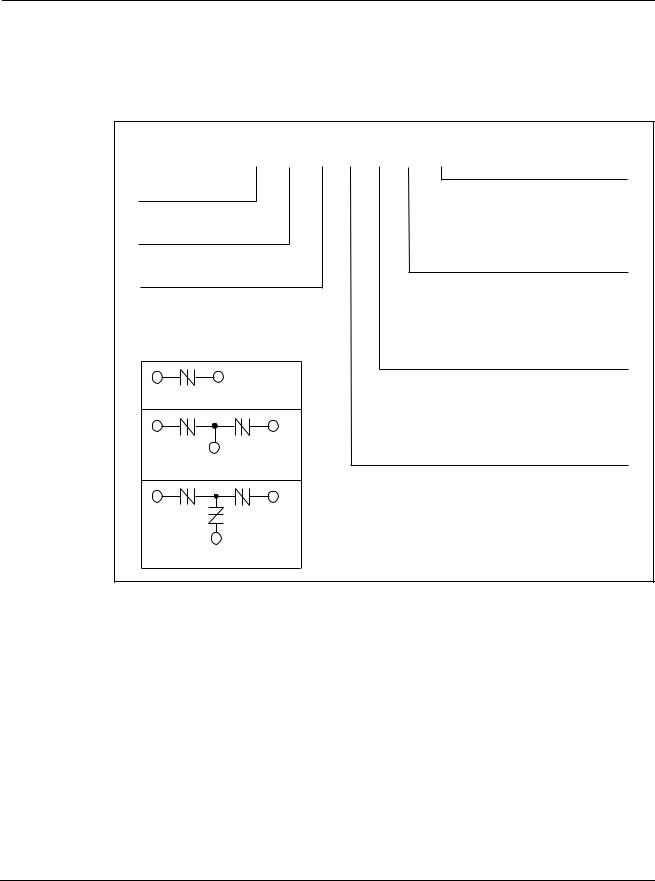
The following illustration shows a description of a sample Battrax device part number.
DEVICE TYPE
B = Battrax
Battrax TYPE
1 = Negative
2 = Positive
3 = Dual
HOLDING CURRENT 05 = 50 mA
10 = 100 mA
16 = 160 mA
20 = 200 mA
B 1 10 1 U A
IPP RATING
A = 50 A (10x560 µs)
B = 100 A (10x560 µs)
C = 500 A (2x10 µs)
PACKAGE TYPE
C = Three-leaded DO-214
U = Six-pin SOIC
CONSTRUCTION VARIABLE 0 = No diode 1 = Diode
4 = Four Battrax Devives
Guide
Product Selection
The following illustration shows a description of a sample asymmetrical SIDACtor device part number.
|
A |
1806 |
U |
C |
4 |
TP |
|
|
|
|
|
|
PACKING OPTIONS |
DEVICE TYPE |
|
|
|
|
|
AP = Ammo pack |
|
|
|
|
|
RP = Reel pack |
|
A = Asymmetrical SIDACtor |
|
|
|
|
|
TP = Tube pack |
MEDIAN VOLTAGE RATING |
|
|
|
|
|
LEAD FORM OPTIONS |
1806 = 180 V and 60 V |
|
|
|
|
|
TO-220 modified type 60, 61, or 62 |
|
|
|
|
|
|
For U type: |
|
|
|
|
|
|
3 = 3 chips |
|
|
|
|
|
|
4 = 4 chips |
|
|
|
|
|
|
6 = 6 chips |
1 |
3 |
|
|
|
|
|
Patented |
|
|
|
|
|
IPP RATING |
2 |
|
|
|
|
|
A = 50 A (10x560 µs) |
|
|
|
|
|
B = 100 A (10x560 µs) |
|
|
|
|
|
|
|
|
3 = Three Matched SIDACtor chips |
|
|
|
|
C = 500 A (2x10 µs) |
|
|
|
|
|
|
|
D = 1000 A (8x20 µs) |
|
|
|
|
|
|
E = 3000 A (8x20 µs) |
|
|
|
|
|
|
PACKAGE TYPE |
|
|
|
|
|
|
A = TO-220 |
|
|
|
|
|
|
M = TO-218 |
|
|
|
|
|
|
U = Six-pin SOIC |
© 2002 Teccor Electronics |
1 - 9 |
|
|
|
http://www.teccor.com |
|
SIDACtor® Data Book and Design Guide |
|
|
|
|
|
+1 972-580-7777 |

Electrical Parameters
Electrical Parameters
Electrical parameters are based on the following definition of conditions:
•On state (also referred to as the crowbar condition) is the low impedance condition reached during full conduction and simulates a short circuit.
•Off state (also referred to as the blocking condition) is the high impedance condition prior to beginning conduction and simulates an open circuit.
CO |
Off-state Capacitance — typical capacitance measured in off state |
di/dt |
Rate of Rise of Current — maximum rated value of the acceptable rate of |
|
rise in current over time |
dv/dt |
Rate of Rise of Voltage — rate of applied voltage over time |
IS |
Switching Current — maximum current required to switch to on state |
IDRM |
Leakage Current — maximum peak off-state current measured at VDRM |
IH |
Holding Current — minimum current required to maintain on state |
IPP |
Peak Pulse Current — maximum rated peak impulse current |
IT |
On-state Current — maximum rated continuous on-state current |
ITSM |
Peak One-cycle Surge Current — maximum rated one-cycle AC current |
VS |
Switching Voltage — maximum voltage prior to switching to on state |
VDRM |
Peak Off-state Voltage — maximum voltage that can be applied while |
|
maintaining off state |
VF |
On-state Forward Voltage — maximum forward voltage measured at rated |
|
on-state current |
VT |
On-state Voltage — maximum voltage measured at rated on-state current |
http://www.teccor.com |
1 - 10 |
© 2002 Teccor Electronics |
+1 972-580-7777 |
|
SIDACtor® Data Book and Design Guide |

Quality and Reliability
Quality and Reliability
It is Teccor’s policy to ship quality products on time. We accomplish this through Total Quality Management based on the fundamentals of customer focus, continuous improvement, and people involvement.
In support of this commitment, Teccor applies the following principles:
•Employees shall be respected, involved, informed, and qualified for their job with appropriate education, training, and experience.
•Customer expectations shall be met or exceeded by consistently shipping products that meet the agreed specifications, quality levels, quantities, schedules, and test and reliability parameters.
•Suppliers shall be selected by considering quality, service, delivery, and cost of ownership.
•Design of products and processes will be driven by customer needs, reliability, and manufacturability.
It is the responsibility of management to incorporate these principles into policies and systems.
It is the responsibility of those in leadership roles to coach their staff and to reinforce these principles.
It is the responsibility of each individual employee to follow the spirit of this statement to ensure that we meet the primary policy — to ship quality products on time.
Guide
Product Selection
© 2002 Teccor Electronics |
1 - 11 |
http://www.teccor.com |
SIDACtor® Data Book and Design Guide |
|
+1 972-580-7777 |

Standard Terms and Conditions
Standard Terms and Conditions
Supplier shall not be bound by any term proposed by Buyer in the absence of written agreement to such term signed by an authorized officer of Supplier.
(1)PRICE:
(A)Supplier reserves the right to change product prices at any time but, whenever practicable, Supplier will give Buyer at least thirty (30) days written notice before the effective date of any price change. Unless Supplier has specifically agreed in writing, signed by an authorized officer of Supplier, that a quoted price shall not be subject to change for a certain time, all products shipped on or after the effective date of a price change may be billed at the new price level.
(B)Whenever Supplier agrees to a modification of Buyer's order (which modification must be in writing and signed by an authorized officer of Supplier), Supplier reserves the right to alter its price, whether or not such price was quoted as “firm”.
(C)Prices do not include federal, state or local taxes, now or hereafter enacted, applicable to the goods sold. Taxes will
be added by Supplier to the sales prices whenever Supplier has legal obligation to collect them and will be paid by Buyer as invoiced unless Buyer provides Supplier with a proper tax exemption certificate.
(2)PRODUCTION: Supplier may, at its sole discretion and at any time, withdraw any catalog item from further production without notice or liability to Buyer.
(3)INTEREST:
(A)All late payments shall bear interest thirty (30) days after the due date stated on the invoice until paid at the lower of one and one-half percent per month or the maximum rate permitted by law. All interest becoming due shall, if not paid when due, be added to principal and bear interest from the due date. At Supplier's option, any payment shall be applied first to interest and then to principal.
(B)It is the intention of the parties to comply with the laws of the jurisdiction governing any agreement between the parties relating to interest. If any construction of the agreement between the parties indicates a different right given to Supplier to demand or receive any sum greater than that permissible by law as interest, such as a mistake in calculation or wording, this paragraph shall override. In any contingency which will cause the interest paid or agreed to be paid to exceed the maximum rate permitted by law, such excess will be applied to the reduction of any principal amount due, or if there is no principal amount due, shall be refunded.
(4)TITLE AND DELIVERY: Title to goods ordered by Buyer and risk of loss or damage in transit or thereafter shall pass to Buyer upon Supplier's delivery of the goods at Supplier's plant or to a common carrier for shipment to Buyer.
(5)CONTINGENCIES: Supplier shall not be responsible for any failure to perform due to causes reasonably beyond its control. These causes shall include, but not be restricted to, fire, storm, flood, earthquake, explosion, accident, acts of public enemy, war rebellion, insurrection, sabotage, epidemic, quarantine restrictions, labor disputes, labor shortages, labor slow downs and sit downs, transportation embargoes, failure or delays in transportation, inability to secure raw materials or machinery for the manufacture of its devices, acts of God, acts of the Federal Government or any agency thereof, acts of any state or local government or agency thereof, and judicial action. Similar causes shall excuse Buyer for failure to take goods ordered by Buyer, from the time Supplier receives written notice from Buyer and for as long as the disabling cause continues, other than for goods already in transit or specially fabricated and not readily saleable to other buyers.
Supplier assumes no responsibility for any tools, dies, and other equipment furnished Supplier by Buyer.
(6)LIMITED WARRANTY AND EXCLUSIVE REMEDY: Supplier warrants all catalog products to be free from defects in materials and workmanship under normal and proper use and application for a period of twelve (12) months from the date code on the product in question (or if none, from the date of delivery to Buyer.) With respect to products assembled, prepared, or manufactured to Buyer's specifications, Supplier warrants only that such products will meet Buyer's specifications upon delivery. As the party responsible for the specifications, Buyer shall be responsible for testing and inspecting the products for adherence to specifications, and Supplier shall have no liability in the absence of such testing and inspection or if the product passes such testing or inspection. THE ABOVE WARRANTY IS THE ONLY WARRANTY EXTENDED BY SUPPLIER, AND IS IN LIEU OF AND EXCLUDES ALL OTHER WARRANTIES AND CONDITIONS, EXPRESSED OR IMPLIED (EXCEPT AS PROVIDED HEREIN AS TO TITLE), ON ANY GOODS OR SERVICES SOLD OR RENDERED BY SUPPLIER, INCLUDING ANY IMPLIED WARRANTIES OF MERCHANTABILITY AND FITNESS FOR A PARTICULAR PURPOSE. THIS WARRANTY WILL NOT CREATE WARRANTY COVERAGE FOR ANY ITEM INTO WHICH ANY PRODUCT SOLD BY SUPPLIER MAY HAVE BEEN INCORPORATED OR ADDED.
SUPPLIER'S ENTIRE LIABILITY AND BUYER'S EXCLUSIVE REMEDY UNDER THIS WARRANTY SHALL BE, AT SUPPLIER'S OPTION, EITHER THE REPLACEMENT OF, REPAIR OF, OR ISSUANCE OF CREDIT TO BUYER'S ACCOUNT WITH SUPPLIER FOR ANY PRODUCTS WHICH ARE PROPERLY RETURNED BY BUYER DURING THE WARRANTY PERIOD. All returns must comply with the following conditions:
© 2002 Teccor Electronics |
1 - 12 |
http://www.teccor.com |
SIDACtor® Data Book and Design Guide |
|
+1 972-580-7777 |

Standard Terms and Conditions
(A)Supplier is to be promptly notified in writing upon discovery of defects by Buyer.
(B)Buyer must obtain a Return Material Authorization (RMA) number from the Supplier prior to returning product.
(C)The defective product is returned to Supplier, transportation charges prepaid by Buyer.
(D)Supplier's examination of such product discloses, to its satisfaction, that such defects have not been caused by misuse, neglect, improper installation, repair, alteration, or accident.
(E)The product is returned in the form it was delivered with any necessary disassembly carried out by Buyer at Buyer's expense.
IN NO EVENT SHALL SUPPLIER, OR ANYONE ELSE ASSOCIATED IN THE CREATION OF ANY OF SUPPLIER'S PRODUCTS OR SERVICES, BE LIABLE TO BUYER FOR INCIDENTAL OR CONSEQUENTIAL DAMAGES OF ANY NATURE INCLUDING LOSS OF PROFITS, LOSS OF USE, BUSINESS INTERUPTION, AND THE LIKE. BUYER ACKNOWLEDGES THAT THE ABOVE WARRANTIES AND LIMITATIONS THEREON ARE APPROPRIATE AND REASONABLE IN EFFECTUATING SUPPLIER'S AND BUYER'S MUTUAL INTENTION TO CONDUCT AN EFFICIENT TRANSACTION AT PRICES MORE ADVANTAGEOUS TO BUYER THAN WOULD BE AVAILABLE IN THE PRESENCE OF OTHER WARRANTIES AND ASSURANCES.
(7)PATENTS: Buyer shall notify Supplier in writing of any claim that any product or any part of use thereof furnished under this agreement constitutes an infringement of any U.S. patent, copyright, trade secret, or other proprietary rights of a third party. Notice shall be given within a reasonable period of time which should in most cases be within ten (10) days of receipt by Buyer of any letter, summons, or complaint pertaining to such a claim. At its option, Supplier may defend at its expense any action brought against Buyer to the extent that it is based on such a claim. Should Supplier choose to defend any such claim, Supplier may fully participate in the defense, settlement, or appeal of any action based on such claim.
Should any product become, or in Supplier's opinion be likely to become, the subject of an action based on any such claim, Supplier may, at its option, as the Buyer's exclusive remedy, either procure for the Buyer the right to continue using the product, replace the product or modify the product to make it noninfringing. IN NO EVENT SHALL SUPPLIER BE LIABLE FOR ANY INCIDENTAL OR CONSEQUENTIAL DAMAGES BASED ON ANY CLAIM OF INFRINGEMENT.
Supplier shall have no liability for any claim based on modifications of a product made by any person or entity other than Supplier, or based on use of a product in conjunction with any other item, unless expressly approved by Supplier. Supplier does not warrant goods against claims of infringement which are assembled, prepared, or manufactured to Buyer's specifications.
(8)NON-WAIVER OF DEFAULT: Each shipment made under any order shall be treated as a separate transaction, but in the event of any default by Buyer, Supplier may decline to make further shipments without in any way affecting its rights under such order. If, despite any default by Buyer, Supplier elects to continue to make shipments, its action shall not constitute a waiver of that or any default by Buyer or in any way affect Supplier's legal remedies for any such default. At any time, Supplier's failure to exercise any right to remedy available to it shall not constitute a waiver of that right or remedy.
(9)TERMINATION: If the products to be furnished under this order are to be used in the performance of a Government contract or subcontract, and the Government terminates such contract in whole or part, this order may be canceled to the extent it was to be used in the canceled portion of said Government contract and the liability of Buyer for termination allowances shall be determined by the then applicable regulations of the Government regarding termination of contracts. Supplier may cancel any unfilled orders unless Buyer shall, upon written notice, immediately pay for all goods delivered or shall pay in advance for all goods ordered but not delivered, or both, at Supplier's option.
(10)LAW: The validity, performance and construction of these terms and conditions and any sale made hereunder shall be governed by the laws of the state of Texas.
(11)ASSIGNS: This agreement shall not be assignable by either Supplier or Buyer. However, should either Supplier or Buyer be sold or transferred in its entirety and as an ongoing business, or should Supplier or Buyer sell or transfer in its entirety and as an ongoing concern, any division, department, or subsidiary responsible in whole or in part for the performance of this Agreement, this Agreement shall be binding upon and inure to the benefit of those successors and assigns of Supplier, Buyer, or such division, department, or subsidiary.
(12)MODIFICATION OF STANDARD TERMS AND CONDITIONS: No attempted or suggested modification of or addition to any of the provisions upon the face or reverse of this form, whether contained or arising in correspondence and/or documents passing between Supplier and Buyer, in any course of dealing between Supplier or Buyer, or in any customary usage prevalent among businesses comparable to those of Supplier and/or Buyer, shall be binding upon Supplier unless made and agreed to in writing and signed by an officer of Supplier.
(13)QUANTITIES: Any variation in quantities of electronic components, or other goods shipped over or under the quantities ordered (not to exceed 5%) shall constitute compliance with Buyer's order and the unit price will continue to apply.
Guide
Product Selection
© 2002 Teccor Electronics |
1 - 13 |
http://www.teccor.com |
SIDACtor® Data Book and Design Guide |
|
+1 972-580-7777 |

NOTES

2 Data Sheets
This section presents complete electrical specifications for Teccor’s SIDACtor solid state overvoltage protection devices.
DO-214AA Package Symbolization. . . . . . . . . . . . . . . . . . . . . . . . . . . . . . . . . . . . . . . . . . . . . . . . . . . . . 2-3
DO-214AA
SIDACtor Device . . . . . . . . . . . . . . . . . . . . . . . . . . . . . . . . . . . . . . . . . . . . . . . . . . . . . . . . . . . . . . 2-4
MicroCapacitance (MC) SC SIDACtor Device . . . . . . . . . . . . . . . . . . . . . . . . . . . . . . . . . . . . . . . . 2-6
MicroCapacitance (MC) SA SIDACtor Device . . . . . . . . . . . . . . . . . . . . . . . . . . . . . . . . . . . . . . . . 2-8
High Surge Current (D-rated) SIDACtor Device. . . . . . . . . . . . . . . . . . . . . . . . . . . . . . . . . . . . . . 2-10
Compak Two-chip SIDACtor Device . . . . . . . . . . . . . . . . . . . . . . . . . . . . . . . . . . . . . . . . . . . . . . 2-12
Ethernet/10BaseT/100BaseT Protector . . . . . . . . . . . . . . . . . . . . . . . . . . . . . . . . . . . . . . . . . . . . 2-14
TO-92
SIDACtor Device . . . . . . . . . . . . . . . . . . . . . . . . . . . . . . . . . . . . . . . . . . . . . . . . . . . . . . . . . . . . . 2-16
MicroCapacitance (MC) SIDACtor Device . . . . . . . . . . . . . . . . . . . . . . . . . . . . . . . . . . . . . . . . . . 2-18
Modified MS-013 (Six-pin Surface Mount)
Balanced Three-chip SIDACtor Device . . . . . . . . . . . . . . . . . . . . . . . . . . . . . . . . . . . . . . . . . . . . 2-20
Multiport SIDACtor Device . . . . . . . . . . . . . . . . . . . . . . . . . . . . . . . . . . . . . . . . . . . . . . . . . . . . . . 2-22
Multiport Balanced SIDACtor Device . . . . . . . . . . . . . . . . . . . . . . . . . . . . . . . . . . . . . . . . . . . . . . 2-24
Modified TO-220
SIDACtor Device . . . . . . . . . . . . . . . . . . . . . . . . . . . . . . . . . . . . . . . . . . . . . . . . . . . . . . . . . . . . . 2-26
Two-chip SIDACtor Device. . . . . . . . . . . . . . . . . . . . . . . . . . . . . . . . . . . . . . . . . . . . . . . . . . . . . . 2-28
Two-chip MicroCapacitance (MC) SIDACtor Device . . . . . . . . . . . . . . . . . . . . . . . . . . . . . . . . . . 2-30
Balanced Three-chip SIDACtor Device . . . . . . . . . . . . . . . . . . . . . . . . . . . . . . . . . . . . . . . . . . . . 2-32
Balanced Three-chip MicroCapacitance (MC) SIDACtor Device . . . . . . . . . . . . . . . . . . . . . . . . . 2-34
LCAS
LCAS Asymmetrical Multiport Device . . . . . . . . . . . . . . . . . . . . . . . . . . . . . . . . . . . . . . . . . . . . . 2-36
LCAS Asymmetrical Discrete Device . . . . . . . . . . . . . . . . . . . . . . . . . . . . . . . . . . . . . . . . . . . . . . 2-38
SIP Hybrid Overvoltage and Overcurrent Protector
Four-Port Balanced Three-chip Protector . . . . . . . . . . . . . . . . . . . . . . . . . . . . . . . . . . . . . . . . . . 2-40
Four-Port Longitudinal Two-chip Protector. . . . . . . . . . . . . . . . . . . . . . . . . . . . . . . . . . . . . . . . . . 2-42
Four-Port Metallic Line Protector . . . . . . . . . . . . . . . . . . . . . . . . . . . . . . . . . . . . . . . . . . . . . . . . . 2-44
SLICs
Fixed Voltage SLIC Protector. . . . . . . . . . . . . . . . . . . . . . . . . . . . . . . . . . . . . . . . . . . . . . . . . . . . 2-46
Twin SLIC Protector . . . . . . . . . . . . . . . . . . . . . . . . . . . . . . . . . . . . . . . . . . . . . . . . . . . . . . . . . . . 2-48
Multiport SLIC Protector. . . . . . . . . . . . . . . . . . . . . . . . . . . . . . . . . . . . . . . . . . . . . . . . . . . . . . . . 2-50
Battrax
Battrax SLIC Protector . . . . . . . . . . . . . . . . . . . . . . . . . . . . . . . . . . . . . . . . . . . . . . . . . . . . . . . . . 2-52
Battrax Dual Negative SLIC Protector . . . . . . . . . . . . . . . . . . . . . . . . . . . . . . . . . . . . . . . . . . . . . 2-54
Battrax Dual Positive/Negative SLIC Protector . . . . . . . . . . . . . . . . . . . . . . . . . . . . . . . . . . . . . . 2-56
Battrax Quad Negative SLIC Protector . . . . . . . . . . . . . . . . . . . . . . . . . . . . . . . . . . . . . . . . . . . . 2-58
CATVs
CATV and HFC SIDACtor Device . . . . . . . . . . . . . . . . . . . . . . . . . . . . . . . . . . . . . . . . . . . . . . . . 2-60
High Surge Current SIDACtor Device . . . . . . . . . . . . . . . . . . . . . . . . . . . . . . . . . . . . . . . . . . . . . 2-62
CATV Line Amplifiers/Power Inserters SIDACtor Device. . . . . . . . . . . . . . . . . . . . . . . . . . . . . . . 2-64
TeleLink Fuse . . . . . . . . . . . . . . . . . . . . . . . . . . . . . . . . . . . . . . . . . . . . . . . . . . . . . . . . . . . . . . . . . . . . 2-66
Acronyms: CATV |
Community Antenna TV |
HFC |
Hybrid Fiber Coax |
LCAS |
Line Circuit Access Switch |
SIP |
Single In-line Package |
SLIC |
Subscriber Line Interface Circuit |
Data Sheets
© 2002 Teccor Electronics |
2-1 |
http://www.teccor.com |
SIDACtor® Data Book and Design Guide |
|
+1 972-580-7777 |

DO-214AA Package Symbolization
DO-214AA Package Symbolization
|
|
|
|
|
|
|
|
|
|
|
|
|
|
|
Part Number |
|
|
Part Number |
|
|
Part Number |
|
|
|
|||
|
Catalog |
Symbolized |
|
|
Catalog |
Symbolized |
|
|
Catalog |
Symbolized |
|
|
|
|
P0080SA |
P-8A |
|
|
P0901SC |
P91C |
|
|
P2300SB |
P23B |
|
|
|
|
|
||||||||||||
|
P0080SA MC |
P-8AM |
|
|
P1100SA |
P11A |
|
|
P2300SC |
P23C |
|
|
|
|
|
|
|
|
|
|
|
|
|
|
|
|
|
|
P0080SB |
P-8B |
|
|
P1100SB |
P11B |
|
|
P2300SD |
P23D |
|
|
Sheets |
|
|
|
|
|
|
|
|
|
|
|
|
|
|
|
P0080SC |
P-8C |
|
|
P1100SC |
P11C |
|
|
P2300SC MC |
P23CM |
|
|
|
|
|
|
|
|
|
|
|
||||||
|
|
|
|
|
|
|
|
|
|
|
|
|
|
|
P0080SD |
P-8D |
|
|
P1100SD |
P11D |
|
|
P2500SA |
P25A |
|
|
|
|
P0080SC MC |
P-8CM |
|
|
P1100SC MC |
P11CM |
|
|
P2500SB |
P25B |
|
|
Data |
|
P0300SA |
P03A |
|
|
P1101CA2 |
P02A |
|
|
P2500SC |
P25C |
|
|
|
|
|
|
|
|
|
|
|
||||||
|
P0300SA MC |
P03AM |
|
|
P1101SA |
P01A |
|
|
P2500SD |
P25D |
|
|
|
|
P0300SB |
P03B |
|
|
P1101SC |
P01C |
|
|
P2500SC MC |
P25CM |
|
|
|
|
|
|
|
|
|
|
|
|
|
|
|
|
|
|
P0300SC |
P03C |
|
|
P1200SA |
P12A |
|
|
P2600SA |
P26A |
|
|
|
|
|
|
|
|
|
|
|
|
|
|
|
|
|
|
P0300SD |
P03D |
|
|
P1200SB |
P12B |
|
|
P2600SB |
P26B |
|
|
|
|
P0300SC MC |
P03CM |
|
|
P1200SC |
P12C |
|
|
P2600SC |
P26C |
|
|
|
|
P0640SA |
P06A |
|
|
P1200SD |
P12D |
|
|
P2600SD |
P26D |
|
|
|
|
P0640SB |
P06B |
|
|
P1200SC MC |
P12CM |
|
|
P2600SC MC |
P26CM |
|
|
|
|
P0640SC |
P06C |
|
|
P1300SA |
P13A |
|
|
P3002CB |
P30B |
|
|
|
|
P0640SD |
P06D |
|
|
P1300SB |
P13B |
|
|
P3002SB |
P30B |
|
|
|
|
|
|
|
|
|
|
|
|
|
|
|
|
|
|
P0640SC MC |
P06CM |
|
|
P1300SC |
P13C |
|
|
P3100SA |
P31A |
|
|
|
|
P0641CA2 |
P62A |
|
|
P1300SD |
P13D |
|
|
P3100SB |
P31B |
|
|
|
|
P0641SA |
P61A |
|
|
P1300SC MC |
P13CM |
|
|
P3100SC |
P31C |
|
|
|
|
P0641SC |
P61C |
|
|
P1500SA |
P15A |
|
|
P3100SD |
P31D |
|
|
|
|
P0720SA |
P07A |
|
|
P1500SB |
P15B |
|
|
P3100SC MC |
P31CM |
|
|
|
|
P0720SB |
P07B |
|
|
P1500SC |
P15C |
|
|
P3500SA |
P35A |
|
|
|
|
|
|
|
|
|
|
|
|
|
|
|
|
|
|
P0720SC |
P07C |
|
|
P1500SD |
P15D |
|
|
P3500SB |
P35B |
|
|
|
|
|
|
|
|
|
|
|
|
|
|
|
|
|
|
P0720SD |
P07D |
|
|
P1500SC MC |
P15CM |
|
|
P3500SC |
P35C |
|
|
|
|
P0720SC MC |
P07CM |
|
|
P1800SA |
P18A |
|
|
P3500SD |
P35D |
|
|
|
|
|
|
|
|
|
|
|
|
|
|
|
|
|
|
P0721CA2 |
P72A |
|
|
P1800SB |
P18B |
|
|
P3500SC MC |
P35CM |
|
|
|
|
P0721SA |
P71A |
|
|
P1800SC |
P18C |
|
|
P6002CB |
P60B |
|
|
|
|
P0721SC |
P71C |
|
|
P1800SD |
P18D |
|
|
B1100CA |
B10A |
|
|
|
|
P0900SA |
P09A |
|
|
P1800SC MC |
P18CM |
|
|
B1100CC |
B10C |
|
|
|
|
|
|
|
|
|
|
|
|
|
|
|
|
|
|
P0900SB |
P09B |
|
|
P2000SA |
P20A |
|
|
B1160CA |
B16A |
|
|
|
|
P0900SC |
P09C |
|
|
P2000SB |
P20B |
|
|
B1160CC |
B16C |
|
|
|
|
|
|
|
|
|
|
|
|
|
|
|
|
|
|
P0900SD |
P09D |
|
|
P2000SC |
P20C |
|
|
B1200CA |
B12A |
|
|
|
|
|
|
|
|
|
|
|
|
|
|
|
|
|
|
P0900SC MC |
P09CM |
|
|
P2000SD |
P20D |
|
|
B1200CC |
B12C |
|
|
|
|
P0901CA2 |
P92A |
|
|
P2000SC MC |
P20CM |
|
|
B2050CA |
B25A |
|
|
|
|
P0901SA |
P91A |
|
|
P2300SA |
P23A |
|
|
B2050CC |
B25C |
|
|
|
|
|
|
|
|
|
|
|
|
|
|
|
|
|
Note: Date code is located below the symbolized part number.
© 2002 Teccor Electronics |
2 - 3 |
http://www.teccor.com |
SIDACtor® Data Book and Design Guide |
|
+1 972-580-7777 |

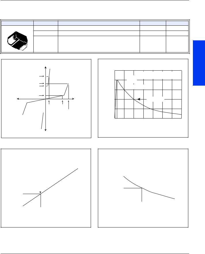
SIDACtor Device
SIDACtor Device
DO-214AA SIDACtor solid state protection devices protect telecommunications equipment such as modems, line cards, fax machines, and other CPE.
SIDACtor devices are used to enable equipment to meet various regulatory requirements including GR 1089, ITU K.20, K.21 and K.45, IEC 60950, UL 60950, and TIA-968 (formerly known as FCC Part 68).
Electrical Parameters
|
|
|
|
|
|
|
|
|
|
|
|
Part |
VDRM |
VS |
VT |
IDRM |
IS |
IT |
IH |
CO |
|
|
Number * |
Volts |
Volts |
Volts |
µAmps |
mAmps |
Amps |
mAmps |
pF |
|
|
P0080S_ |
6 |
25 |
4 |
5 |
800 |
2.2 |
50 |
100 |
|
|
P0300S_ |
25 |
40 |
4 |
5 |
800 |
2.2 |
50 |
110 |
|
|
P0640S_ |
58 |
77 |
4 |
5 |
800 |
2.2 |
150 |
50 |
|
|
P0720S_ |
65 |
88 |
4 |
5 |
800 |
2.2 |
150 |
50 |
|
|
|
|
|
|
|
|
|
|
|
|
|
P0900S_ |
75 |
98 |
4 |
5 |
800 |
2.2 |
150 |
50 |
|
|
P1100S_ |
90 |
130 |
4 |
5 |
800 |
2.2 |
150 |
40 |
|
|
P1300S_ |
120 |
160 |
4 |
5 |
800 |
2.2 |
150 |
40 |
|
|
P1500S_ |
140 |
180 |
4 |
5 |
800 |
2.2 |
150 |
40 |
|
|
P1800S_ |
170 |
220 |
4 |
5 |
800 |
2.2 |
150 |
30 |
|
|
P2300S_ |
190 |
260 |
4 |
5 |
800 |
2.2 |
150 |
30 |
|
|
|
|
|
|
|
|
|
|
|
|
|
P2600S_ |
220 |
300 |
4 |
5 |
800 |
2.2 |
150 |
30 |
|
|
|
|
|
|
|
|
|
|
|
|
|
P3100S_ |
275 |
350 |
4 |
5 |
800 |
2.2 |
150 |
30 |
|
|
P3500S_ |
320 |
400 |
4 |
5 |
800 |
2.2 |
150 |
30 |
|
|
|
|
|
|
|
|
|
|
|
|
* For individual “SA”, “SB”, and “SC” surge ratings, see table below. General Notes:
•All measurements are made at an ambient temperature of 25 °C. IPP applies to -40 °C through +85 °C temperature range.
•IPP is a repetitive surge rating and is guaranteed for the life of the product.
•Listed SIDACtor devices are bi-directional. All electrical parameters and surge ratings apply to forward and reverse polarities.
•VDRM is measured at IDRM.
•VS is measured at 100 V/µs.
•Special voltage (VS and VDRM) and holding current (IH) requirements are available upon request.
•Off-state capacitance is measured at 1 MHz with a 2 V bias and is a typical value for “SA” and “SB” product. “SC” capacitance is approximately 2x the listed value. The off-state capacitance of the P0080SB is equal to the “SC” device.
Surge Ratings
|
|
|
|
|
|
|
|
|
|
|
|
IPP |
IPP |
IPP |
IPP |
IPP |
ITSM |
di/dt |
|
|
Series |
2x10 µs |
8x20 µs |
10x160 µs |
10x560 µs |
10x1000 µs |
60 Hz |
|
|
|
Amps |
Amps |
Amps |
Amps |
Amps |
Amps |
Amps/µs |
|
|
|
A |
150 |
150 |
90 |
50 |
45 |
20 |
500 |
|
|
B |
250 |
250 |
150 |
100 |
80 |
30 |
500 |
|
|
C |
500 |
400 |
200 |
150 |
100 |
30 |
500 |
|
|
|
|
|
|
|
|
|
|
|
http://www.teccor.com |
2 - 4 |
© 2002 Teccor Electronics |
+1 972-580-7777 |
|
SIDACtor® Data Book and Design Guide |
SIDACtor Device
Thermal Considerations
Package |
Symbol |
Parameter |
Value |
Unit |
DO-214AA |
TJ |
Operating Junction Temperature Range |
-40 to +150 |
°C |
|
TS |
Storage Temperature Range |
-65 to +150 |
°C |
|
R JA |
Thermal Resistance: Junction to Ambient |
90 |
°C/W |
+I |
|
+I |
|
IIT |
|
T |
|
IS |
|
IH |
|
IDRM |
|
--V |
+V |
VT |
VDRM |
T |
DRM |
|
V |
|
VSS |
-I |
|
-I |
|
V-I Characteristics |
|
IPP – Peak Pulse Current – %IPP
100 

50
0
0 tr
tr = rise time to peak value Peak td = decay time to half value
Value
Waveform = tr x td
Half Value
td
t – Time (µs)
tr x td Pulse Wave-form
Data Sheets
|
14 |
|
|
|
|
|
|
|
|
|
|
|
|
|
|
|
|
|
|
|
|
|
|
|
|
|
|
|
|
|
|
|
|
% |
12 |
|
|
|
|
|
|
|
|
|
|
|
|
|
|
|
|
|
|
|
|
|
|
|
|
|
|
|
|
|
|
||
– |
10 |
|
|
|
|
|
|
|
|
|
|
|
|
|
|
|
Change |
|
|
|
|
|
|
|
|
|
|
|
|
|
|
|
|
8 |
|
|
|
|
|
|
|
|
|
|
|
|
|
|
|
|
|
|
|
|
|
|
|
|
|
|
|
|
|
|
|
|
|
|
6 |
|
|
|
|
|
|
|
|
|
|
|
|
|
|
|
|
|
|
|
|
25 ˚C |
|
|
|
|
|
|
|
||||
S |
4 |
|
|
|
|
|
|
|
|
|
|
|
||||
of V |
2 |
|
|
|
|
|
|
|
|
|
|
|
|
|
|
|
|
|
|
|
|
|
|
|
|
|
|
|
|
|
|
||
Percent |
0 |
|
|
|
|
|
|
|
|
|
|
|
|
|
|
|
|
|
|
|
|
|
|
|
|
|
|
|
|
|
|
|
|
|
-4 |
|
|
|
|
|
|
|
|
|
|
|
|
|
|
|
|
|
|
|
|
|
|
|
|
|
|
|
|
|
|
|
|
|
-6 |
|
|
|
|
|
|
|
|
|
|
|
|
|
|
|
|
|
|
|
|
|
|
|
|
|
|
|
|
|
|
|
|
|
-8 |
|
|
|
|
|
|
|
|
|
|
|
|
|
|
|
|
-40 -20 0 20 40 60 80 100 120 140 160 |
|||||||||||||||
|
|
|||||||||||||||
|
|
|
|
Junction Temperature (TJ) – ˚C |
||||||||||||
Normalized VS Change versus Junction Temperature
|
|
˚C) |
2.0 |
|
|
|
|
|
|
|
|
|
|
|
|
|
|
|
|
|
|
|
|
|
|
|
|
|
|
|
|
||
|
|
1.8 |
|
|
|
|
|
|
|
|
|
|
|
|
|
|
|
|
|
|
|
|
|
|
|
|
|
|
|
|
|
||
|
|
25 |
|
|
|
|
|
|
|
|
|
|
|
|
|
|
H |
|
1.6 |
|
|
|
|
|
|
|
|
|
|
|
|
|
|
|
= |
|
|
|
|
|
|
|
|
|
|
|
|
|
||
|
1.4 |
|
|
|
|
|
|
|
|
|
|
|
|
|
||
I |
|
C |
|
|
|
|
|
|
|
|
|
|
|
|
|
|
|
|
|
|
|
25 ˚C |
|
|
|
|
|
|
|
|
|||
|
|
|
|
|
|
|
|
|
|
|
|
|
|
|||
|
|
(T |
1.2 |
|
|
|
|
|
|
|
|
|
|
|
||
|
|
|
|
|
|
|
|
|
|
|
|
|
|
|
||
|
|
H |
1.0 |
|
|
|
|
|
|
|
|
|
|
|
|
|
|
|
I |
|
|
|
|
|
|
|
|
|
|
|
|
|
|
|
of |
0.8 |
|
|
|
|
|
|
|
|
|
|
|
|
|
|
|
Ratio |
|
|
|
|
|
|
|
|
|
|
|
|
|
||
|
|
|
|
|
|
|
|
|
|
|
|
|
|
|||
|
0.6 |
|
|
|
|
|
|
|
|
|
|
|
|
|
||
|
|
|
|
|
|
|
|
|
|
|
|
|
|
|
|
|
|
|
|
0.4 |
|
|
|
|
|
|
|
|
|
|
|
|
|
|
|
|
|
|
|
|
|
|
|
|
|
|
|
|
|
|
|
|
|
-40 -20 0 20 40 60 80 100 120 140 160 |
|||||||||||||
|
|
|
|
|
Case Temperature (TC) – ˚C |
|||||||||||
Normalized DC Holding Current versus Case Temperature
© 2002 Teccor Electronics |
2 - 5 |
http://www.teccor.com |
SIDACtor® Data Book and Design Guide |
|
+1 972-580-7777 |

MicroCapacitance (MC) SC SIDACtor Device
MicroCapacitance (MC) SC SIDACtor Device
The DO-214AA SC MC SIDACtor series is intended for applications sensitive to load values. Typically, high speed connections require a lower capacitance. CO values for the MicroCapacitance device are 40% lower than a standard SC part.
This MC SIDACtor series is used to enable equipment to meet various regulatory requirements including GR 1089, IEC 60950, UL 60950, and TIA-968 (formerly known as FCC Part 68). Contact factory regarding ITU K.20, K.21, and K.45.
Electrical Parameters
|
|
|
|
|
|
|
|
|
|
|
|
Part |
VDRM |
VS |
VT |
IDRM |
IS |
IT |
IH |
CO |
|
|
Number * |
Volts |
Volts |
Volts |
µAmps |
mAmps |
Amps |
mAmps |
pF |
|
|
P0080SC MC ** |
6 |
25 |
4 |
5 |
800 |
2.2 |
50 |
55 |
|
|
P0300SC MC ** |
25 |
40 |
4 |
5 |
800 |
2.2 |
50 |
35 |
|
|
P0640SC MC |
58 |
77 |
4 |
5 |
800 |
2.2 |
150 |
60 |
|
|
P0720SC MC |
65 |
88 |
4 |
5 |
800 |
2.2 |
150 |
60 |
|
|
P0900SC MC |
75 |
98 |
4 |
5 |
800 |
2.2 |
150 |
60 |
|
|
|
|
|
|
|
|
|
|
|
|
|
P1100SC MC |
90 |
130 |
4 |
5 |
800 |
2.2 |
150 |
50 |
|
|
|
|
|
|
|
|
|
|
|
|
|
P1300SC MC |
120 |
160 |
4 |
5 |
800 |
2.2 |
150 |
50 |
|
|
P1500SC MC |
140 |
180 |
4 |
5 |
800 |
2.2 |
150 |
50 |
|
|
P1800SC MC |
170 |
220 |
4 |
5 |
800 |
2.2 |
150 |
40 |
|
|
P2300SC MC |
190 |
260 |
4 |
5 |
800 |
2.2 |
150 |
40 |
|
|
P2600SC MC |
220 |
300 |
4 |
5 |
800 |
2.2 |
150 |
40 |
|
|
P3100SC MC |
275 |
350 |
4 |
5 |
800 |
2.2 |
150 |
40 |
|
|
|
|
|
|
|
|
|
|
|
|
|
P3500SC MC |
320 |
400 |
4 |
5 |
800 |
2.2 |
150 |
40 |
|
|
|
|
|
|
|
|
|
|
|
|
*For surge ratings, see table below.
**Contact factory for release date.
General Notes:
•All measurements are made at an ambient temperature of 25 °C. IPP applies to -40 °C through +85 °C temperature range.
•IPP is a repetitive surge rating and is guaranteed for the life of the product.
•Listed SIDACtor devices are bi-directional. All electrical parameters and surge ratings apply to forward and reverse polarities.
•VDRM is measured at IDRM.
•VS is measured at 100 V/µs.
•Special voltage (VS and VDRM) and holding current (IH) requirements are available upon request.
•Off-state capacitance is measured at 1 MHz with a 2 V bias.
Surge Ratings
|
|
|
|
|
|
|
|
|
|
|
|
IPP |
IPP |
IPP |
IPP |
IPP |
ITSM |
di/dt |
|
|
Series |
2x10 µs |
8x20 µs |
10x160 µs |
10x560 µs |
10x1000 µs |
60 Hz |
|
|
|
Amps |
Amps |
Amps |
Amps |
Amps |
Amps |
Amps/µs |
|
|
|
C |
500 |
400 |
200 |
150 |
100 |
30 |
500 |
|
|
|
|
|
|
|
|
|
|
|
http://www.teccor.com |
2 - 6 |
© 2002 Teccor Electronics |
+1 972-580-7777 |
|
SIDACtor® Data Book and Design Guide |
MicroCapacitance (MC) SC SIDACtor Device
Thermal Considerations
Package |
Symbol |
Parameter |
Value |
Unit |
DO-214AA |
TJ |
Operating Junction Temperature Range |
-40 to +150 |
°C |
|
TS |
Storage Temperature Range |
-65 to +150 |
°C |
|
R JA |
Thermal Resistance: Junction to Ambient |
90 |
°C/W |
+I |
|
+I |
|
IIT |
|
T |
|
IS |
|
IH |
|
IDRM |
|
--V |
+V |
VT |
VDRM |
T |
DRM |
|
V |
|
VSS |
-I |
|
-I |
|
V-I Characteristics |
|
IPP – Peak Pulse Current – %IPP
100 

50
0
0 tr
tr = rise time to peak value Peak td = decay time to half value
Value
Waveform = tr x td
Half Value
td
t – Time (µs)
tr x td Pulse Wave-form
Data Sheets
|
14 |
|
|
|
|
|
|
|
|
|
|
|
|
|
|
|
|
|
|
|
|
|
|
|
|
|
|
|
|
|
|
|
|
% |
12 |
|
|
|
|
|
|
|
|
|
|
|
|
|
|
|
|
|
|
|
|
|
|
|
|
|
|
|
|
|
|
||
– |
10 |
|
|
|
|
|
|
|
|
|
|
|
|
|
|
|
Change |
|
|
|
|
|
|
|
|
|
|
|
|
|
|
|
|
8 |
|
|
|
|
|
|
|
|
|
|
|
|
|
|
|
|
|
|
|
|
|
|
|
|
|
|
|
|
|
|
|
|
|
|
6 |
|
|
|
|
|
|
|
|
|
|
|
|
|
|
|
|
|
|
|
|
25 ˚C |
|
|
|
|
|
|
|
||||
S |
4 |
|
|
|
|
|
|
|
|
|
|
|
||||
of V |
2 |
|
|
|
|
|
|
|
|
|
|
|
|
|
|
|
|
|
|
|
|
|
|
|
|
|
|
|
|
|
|
||
Percent |
0 |
|
|
|
|
|
|
|
|
|
|
|
|
|
|
|
|
|
|
|
|
|
|
|
|
|
|
|
|
|
|
|
|
|
-4 |
|
|
|
|
|
|
|
|
|
|
|
|
|
|
|
|
|
|
|
|
|
|
|
|
|
|
|
|
|
|
|
|
|
-6 |
|
|
|
|
|
|
|
|
|
|
|
|
|
|
|
|
|
|
|
|
|
|
|
|
|
|
|
|
|
|
|
|
|
-8 |
|
|
|
|
|
|
|
|
|
|
|
|
|
|
|
|
-40 -20 0 20 40 60 80 100 120 140 160 |
|||||||||||||||
|
|
|||||||||||||||
|
|
|
|
Junction Temperature (TJ) – ˚C |
||||||||||||
Normalized VS Change versus Junction Temperature
|
|
˚C) |
2.0 |
|
|
|
|
|
|
|
|
|
|
|
|
|
|
|
|
|
|
|
|
|
|
|
|
|
|
|
|
||
|
|
1.8 |
|
|
|
|
|
|
|
|
|
|
|
|
|
|
|
|
|
|
|
|
|
|
|
|
|
|
|
|
|
||
|
|
25 |
|
|
|
|
|
|
|
|
|
|
|
|
|
|
H |
|
1.6 |
|
|
|
|
|
|
|
|
|
|
|
|
|
|
|
= |
|
|
|
|
|
|
|
|
|
|
|
|
|
||
|
1.4 |
|
|
|
|
|
|
|
|
|
|
|
|
|
||
I |
|
C |
|
|
|
|
|
|
|
|
|
|
|
|
|
|
|
|
|
|
|
25 ˚C |
|
|
|
|
|
|
|
|
|||
|
|
|
|
|
|
|
|
|
|
|
|
|
|
|||
|
|
(T |
1.2 |
|
|
|
|
|
|
|
|
|
|
|
||
|
|
|
|
|
|
|
|
|
|
|
|
|
|
|
||
|
|
H |
1.0 |
|
|
|
|
|
|
|
|
|
|
|
|
|
|
|
I |
|
|
|
|
|
|
|
|
|
|
|
|
|
|
|
of |
0.8 |
|
|
|
|
|
|
|
|
|
|
|
|
|
|
|
Ratio |
|
|
|
|
|
|
|
|
|
|
|
|
|
||
|
|
|
|
|
|
|
|
|
|
|
|
|
|
|||
|
0.6 |
|
|
|
|
|
|
|
|
|
|
|
|
|
||
|
|
|
|
|
|
|
|
|
|
|
|
|
|
|
|
|
|
|
|
0.4 |
|
|
|
|
|
|
|
|
|
|
|
|
|
|
|
|
|
|
|
|
|
|
|
|
|
|
|
|
|
|
|
|
|
-40 -20 0 20 40 60 80 100 120 140 160 |
|||||||||||||
|
|
|
|
|
Case Temperature (TC) – ˚C |
|||||||||||
Normalized DC Holding Current versus Case Temperature
© 2002 Teccor Electronics |
2 - 7 |
http://www.teccor.com |
SIDACtor® Data Book and Design Guide |
|
+1 972-580-7777 |

MicroCapacitance (MC) SA SIDACtor Device
MicroCapacitance (MC) SA SIDACtor Device
The DO-214AA SA MC SIDACtor series is intended for applications sensitive to load values. Typically, high speed connections require a lower capacitance. CO values for the MicroCapacitance device are 40% lower than a standard SA part.
This MC SIDACtor series is used to enable equipment to meet various regulatory requirements including GR 1089, ITU K.20, K.21, and K.45, IEC 60950, UL 60950, and TIA968 (formerly known as FCC Part 68).
Electrical Parameters
|
|
|
|
|
|
|
|
|
|
|
|
Part |
VDRM |
VS |
VT |
IDRM |
IS |
IT |
IH |
CO |
|
|
Number * |
Volts |
Volts |
Volts |
µAmps |
mAmps |
Amps |
mAmps |
pF |
|
|
P0080SA MC |
6 |
25 |
4 |
5 |
800 |
2.2 |
50 |
45 |
|
|
P0300SA MC |
25 |
40 |
4 |
5 |
800 |
2.2 |
50 |
25 |
|
|
|
|
|
|
|
|
|
|
|
|
* For surge ratings, see table below. General Notes:
•All measurements are made at an ambient temperature of 25 °C. IPP applies to -40 °C through +85 °C temperature range.
•IPP is a repetitive surge rating and is guaranteed for the life of the product.
•Listed SIDACtor devices are bi-directional. All electrical parameters and surge ratings apply to forward and reverse polarities.
•VDRM is measured at IDRM.
•VS is measured at 100 V/µs.
•Special voltage (VS and VDRM) and holding current (IH) requirements are available upon request.
•Off-state capacitance is measured at 1 MHz with a 2 V bias.
Surge Ratings
|
|
IPP |
IPP |
IPP |
IPP |
IPP |
ITSM |
di/dt |
|
|
|
2x10 µs |
8x20 µs |
10x160 µs |
10x560 µs |
10x1000 µs |
60 Hz |
|
|
|
Series |
Amps |
Amps |
Amps |
Amps |
Amps |
Amps |
Amps/µs |
|
|
A |
150 |
150 |
90 |
50 |
45 |
20 |
500 |
|
|
|
|
|
|
|
|
|
|
|
http://www.teccor.com |
2 - 8 |
© 2002 Teccor Electronics |
+1 972-580-7777 |
|
SIDACtor® Data Book and Design Guide |

MicroCapacitance (MC) SA SIDACtor Device
Thermal Considerations
Package |
Symbol |
Parameter |
Value |
Unit |
DO-214AA |
TJ |
Operating Junction Temperature Range |
-40 to +150 |
°C |
|
TS |
Storage Temperature Range |
-65 to +150 |
°C |
|
R JA |
Thermal Resistance: Junction to Ambient |
90 |
°C/W |
+I |
|
+I |
|
IIT |
|
T |
|
IS |
|
IH |
|
IDRM |
|
--V |
+V |
VT |
VDRM |
T |
DRM |
|
V |
|
VSS |
-I |
|
-I |
|
V-I Characteristics |
|
IPP – Peak Pulse Current – %IPP
100 

50
0
0 tr
tr = rise time to peak value Peak td = decay time to half value
Value
Waveform = tr x td
Half Value
td
t – Time (µs)
tr x td Pulse Wave-form
Data Sheets
|
14 |
|
|
|
|
|
|
|
|
|
|
|
|
|
|
|
|
|
|
|
|
|
|
|
|
|
|
|
|
|
|
|
|
% |
12 |
|
|
|
|
|
|
|
|
|
|
|
|
|
|
|
|
|
|
|
|
|
|
|
|
|
|
|
|
|
|
||
– |
10 |
|
|
|
|
|
|
|
|
|
|
|
|
|
|
|
Change |
|
|
|
|
|
|
|
|
|
|
|
|
|
|
|
|
8 |
|
|
|
|
|
|
|
|
|
|
|
|
|
|
|
|
|
|
|
|
|
|
|
|
|
|
|
|
|
|
|
|
|
|
6 |
|
|
|
|
|
|
|
|
|
|
|
|
|
|
|
|
|
|
|
|
25 ˚C |
|
|
|
|
|
|
|
||||
S |
4 |
|
|
|
|
|
|
|
|
|
|
|
||||
of V |
2 |
|
|
|
|
|
|
|
|
|
|
|
|
|
|
|
|
|
|
|
|
|
|
|
|
|
|
|
|
|
|
||
Percent |
0 |
|
|
|
|
|
|
|
|
|
|
|
|
|
|
|
|
|
|
|
|
|
|
|
|
|
|
|
|
|
|
|
|
|
-4 |
|
|
|
|
|
|
|
|
|
|
|
|
|
|
|
|
|
|
|
|
|
|
|
|
|
|
|
|
|
|
|
|
|
-6 |
|
|
|
|
|
|
|
|
|
|
|
|
|
|
|
|
|
|
|
|
|
|
|
|
|
|
|
|
|
|
|
|
|
-8 |
|
|
|
|
|
|
|
|
|
|
|
|
|
|
|
|
-40 -20 0 20 40 60 80 100 120 140 160 |
|||||||||||||||
|
|
|||||||||||||||
|
|
|
|
Junction Temperature (TJ) – ˚C |
||||||||||||
Normalized VS Change versus Junction Temperature
|
|
˚C) |
2.0 |
|
|
|
|
|
|
|
|
|
|
|
|
|
|
|
|
|
|
|
|
|
|
|
|
|
|
|
|
||
|
|
1.8 |
|
|
|
|
|
|
|
|
|
|
|
|
|
|
|
|
|
|
|
|
|
|
|
|
|
|
|
|
|
||
|
|
25 |
|
|
|
|
|
|
|
|
|
|
|
|
|
|
H |
|
1.6 |
|
|
|
|
|
|
|
|
|
|
|
|
|
|
|
= |
|
|
|
|
|
|
|
|
|
|
|
|
|
||
|
1.4 |
|
|
|
|
|
|
|
|
|
|
|
|
|
||
I |
|
C |
|
|
|
|
|
|
|
|
|
|
|
|
|
|
|
|
|
|
|
25 ˚C |
|
|
|
|
|
|
|
|
|||
|
|
|
|
|
|
|
|
|
|
|
|
|
|
|||
|
|
(T |
1.2 |
|
|
|
|
|
|
|
|
|
|
|
||
|
|
|
|
|
|
|
|
|
|
|
|
|
|
|
||
|
|
H |
1.0 |
|
|
|
|
|
|
|
|
|
|
|
|
|
|
|
I |
|
|
|
|
|
|
|
|
|
|
|
|
|
|
|
of |
0.8 |
|
|
|
|
|
|
|
|
|
|
|
|
|
|
|
Ratio |
|
|
|
|
|
|
|
|
|
|
|
|
|
||
|
|
|
|
|
|
|
|
|
|
|
|
|
|
|||
|
0.6 |
|
|
|
|
|
|
|
|
|
|
|
|
|
||
|
|
|
|
|
|
|
|
|
|
|
|
|
|
|
|
|
|
|
|
0.4 |
|
|
|
|
|
|
|
|
|
|
|
|
|
|
|
|
|
|
|
|
|
|
|
|
|
|
|
|
|
|
|
|
|
-40 -20 0 20 40 60 80 100 120 140 160 |
|||||||||||||
|
|
|
|
|
Case Temperature (TC) – ˚C |
|||||||||||
Normalized DC Holding Current versus Case Temperature
© 2002 Teccor Electronics |
2 - 9 |
http://www.teccor.com |
SIDACtor® Data Book and Design Guide |
|
+1 972-580-7777 |

High Surge Current (D-rated) SIDACtor Device
High Surge Current (D-rated) SIDACtor Device
DO-214AA SIDACtor solid state protection devices with a D surge rating protect telecommunications equipment such as modems, line cards, fax machines, and other CPE.
These SIDACtor devices withstand simultaneous surges incurred in GR 1089 lightning tests. (See "First Level Lightning Surge Test" on page 4-5.) Surge ratings are twice that of a device with a C surge rating. This allows a discrete surface mount version of Teccor’s patented “Y” configuration. (US Patent 4,905,119)
SIDACtor devices are used to enable equipment to meet various regulatory requirements including GR 1089, ITU K.20, K.21 and K.45, IEC 60950, UL 60950, and TIA-968 (formerly known as FCC Part 68).
Electrical Parameters
|
|
|
|
|
|
|
|
|
|
|
|
Part |
VDRM |
VS |
VT |
IDRM |
IS |
IT |
IH |
CO |
|
|
Number * |
Volts |
Volts |
Volts |
µAmps |
mAmps |
Amps |
mAmps |
pF |
|
|
P0080SD ** |
6 |
25 |
4 |
5 |
800 |
2.2 |
50 |
200 |
|
|
|
|
|
|
|
|
|
|
|
|
|
P0300SD ** |
25 |
40 |
4 |
5 |
800 |
2.2 |
50 |
220 |
|
|
|
|
|
|
|
|
|
|
|
|
|
P0640SD ** |
58 |
77 |
4 |
5 |
800 |
2.2 |
50 |
100 |
|
|
P0720SD ** |
65 |
88 |
4 |
5 |
800 |
2.2 |
50 |
100 |
|
|
P0900SD ** |
75 |
98 |
4 |
5 |
800 |
2.2 |
50 |
100 |
|
|
P1100SD |
90 |
130 |
4 |
5 |
800 |
2.2 |
50 |
80 |
|
|
P1300SD |
120 |
160 |
4 |
5 |
800 |
2.2 |
50 |
80 |
|
|
|
|
|
|
|
|
|
|
|
|
|
P1500SD |
140 |
180 |
4 |
5 |
800 |
2.2 |
50 |
80 |
|
|
|
|
|
|
|
|
|
|
|
|
|
P1800SD |
170 |
220 |
4 |
5 |
800 |
2.2 |
50 |
60 |
|
|
|
|
|
|
|
|
|
|
|
|
|
P2300SD |
190 |
260 |
4 |
5 |
800 |
2.2 |
50 |
60 |
|
|
P2600SD |
220 |
300 |
4 |
5 |
800 |
2.2 |
50 |
60 |
|
|
P3100SD |
275 |
350 |
4 |
5 |
800 |
2.2 |
50 |
60 |
|
|
P3500SD |
320 |
400 |
4 |
5 |
800 |
2.2 |
50 |
60 |
|
|
|
|
|
|
|
|
|
|
|
|
*For surge ratings, see table below.
**Contact factory for release date.
General Notes:
•All measurements are made at an ambient temperature of 25 °C. IPP applies to -40 °C through +85 °C temperature range.
•IPP is a repetitive surge rating and is guaranteed for the life of the product.
•Listed SIDACtor devices are bi-directional. All electrical parameters and surge ratings apply to forward and reverse polarities.
•VDRM is measured at IDRM.
•VS is measured at 100 V/µs.
•Special voltage (VS and VDRM) and holding current (IH) requirements are available upon request.
•Off-state capacitance is measured at 1 MHz with a 2 V bias and is a typical value.
Surge Ratings
|
|
IPP |
IPP |
IPP |
IPP |
IPP |
ITSM |
di/dt |
|
|
|
2x10 µs |
8x20 µs |
10x160 µs |
10x560 µs |
10x1000 µs |
60 Hz |
|
|
|
Series |
Amps |
Amps |
Amps |
Amps |
Amps |
Amps |
Amps/µs |
|
|
D |
1000 |
800 |
400 |
300 |
200 |
50 |
1000 |
|
|
|
|
|
|
|
|
|
|
|
http://www.teccor.com |
2 - 10 |
© 2002 Teccor Electronics |
+1 972-580-7777 |
|
SIDACtor® Data Book and Design Guide |

High Surge Current (D-rated) SIDACtor Device
Thermal Considerations |
|
|
|
|
|
|
|
Package |
Symbol |
|
Parameter |
|
|
Value |
Unit |
DO-214AA |
TJ |
Operating Junction Temperature Range |
|
-40 to +150 |
°C |
||
|
TS |
Storage Temperature Range |
|
|
-65 to +150 |
°C |
|
|
R JA |
Thermal Resistance: Junction to Ambient |
|
90 |
°C/W |
||
|
+I |
|
|
|
|
|
Sheets |
|
|
|
|
|
|
Data |
|
|
+I |
|
|
|
|
|
|
|
|
|
|
|
|
|
|
IIT |
|
|
PP |
|
|
tr = rise time to peak value |
|
|
|
%I |
|
Peak |
td = decay time to half value |
||
T |
|
|
100 |
||||
IS |
|
|
– |
Value |
|
|
|
|
|
Current |
|
|
|
||
IH |
|
|
|
Waveform = tr x td |
|
||
|
|
Pulse |
|
|
|||
--V |
|
+V |
50 |
|
Half Value |
|
|
IDRM |
|
|
|
|
|
|
|
|
T |
DRM |
Peak |
|
|
|
|
|
VT |
VDRM |
|
|
|
|
|
|
|
V |
– |
|
|
|
|
|
|
|
|
|
|
|
|
|
|
VSS |
PP |
|
|
|
|
|
|
|
I |
0 |
|
|
|
|
|
|
|
td |
|
|
|
|
|
|
|
0 tr |
t – Time (µs) |
|
|
|
|
|
|
|
|
|
|
|
-I |
|
|
|
|
|
|
|
-I |
|
|
|
|
|
|
V-I Characteristics |
|
|
tr x td Pulse Wave-form |
|
|
||
S
Percent of V Change – %
14
12
10
8
6
25 ˚C
4
2
0
-4
-6
-8
-40 -20 0 20 40 60 80 100 120 140 160
Junction Temperature (TJ) – ˚C
H |
|
25˚C) |
|
= |
|
I |
|
|
|
|
C |
|
|
(T |
|
|
H |
|
|
I |
|
Ratio of |
|
2.0
1.8
1.6
1.4
1.225 ˚C
1.0
0.8
0.6
0.4 -40 -20 0 20 40 60 80 100 120 140 160
Case Temperature (TC) – ˚C
Normalized VS Change versus Junction Temperature |
Normalized DC Holding Current versus Case Temperature |
© 2002 Teccor Electronics |
2 - 11 |
http://www.teccor.com |
SIDACtor® Data Book and Design Guide |
|
+1 972-580-7777 |

Compak Two-chip SIDACtor Device
Compak Two-chip SIDACtor Device
1
(T)
3
(R)
|
The modified DO-214AA SIDACtor device provides low-cost, longitudinal protection. |
2 |
SIDACtor devices are used to enable equipment to meet various regulatory requirements |
(G) |
|
|
including GR 1089, ITU K.20, K.21, and K.45, IEC 60950, UL 60950, and TIA-968 (formerly |
|
known as FCC Part 68). |
Electrical Parameters
|
|
|
|
|
|
|
|
|
|
|
|
|
|
|
|
VDRM |
VS |
VDRM |
|
VS |
|
|
|
|
|
CO |
|
|
Part |
Volts |
Volts |
Volts |
|
Volts |
VT |
IDRM |
IS |
IT |
IH |
pF |
|
|
Number |
Pins1-2, 2-3 |
Pins 1-3 |
|
Volts |
µAmps |
mAmps |
Amps |
mAmps |
Pins 1-3 |
|
||
|
P3002CA |
140 |
180 |
280 |
|
360 |
4 |
5 |
800 |
1 |
120 |
15 |
|
|
P6002CA |
275 |
350 |
550 |
|
700 |
4 |
5 |
800 |
1 |
120 |
15 |
|
|
|
|
|
|
|
|
|
|
|
|
|
|
|
* For surge ratings, see table below. General Notes:
•All measurements are made at an ambient temperature of 25 °C. IPP applies to -40 °C through +85 °C temperature range.
•IPP is a repetitive surge rating and is guaranteed for the life of the product.
•Listed SIDACtor devices are bi-directional. All electrical parameters and surge ratings apply to forward and reverse polarities.
•VDRM is measured at IDRM.
•VS is measured at 100 V/µs.
•Special voltage (VS and VDRM) and holding current (IH) requirements are available upon request.
•Off-state capacitance is measured between Pins 1-3 at 1 MHz with a 2 V bias.
•UL 60950 creepage requirements must be considered.
Surge Ratings
|
|
|
|
|
|
|
|
|
|
|
|
IPP |
IPP |
IPP |
IPP |
IPP |
ITSM |
di/dt |
|
|
|
2x10 µs |
8x20 µs |
10x160 µs |
10x560 µs |
10x1000 µs |
60 Hz |
|
|
|
Series |
Amps |
Amps |
Amps |
Amps |
Amps |
Amps |
Amps/µs |
|
|
A |
150 |
150 |
90 |
50 |
45 |
20 |
500 |
|
|
|
|
|
|
|
|
|
|
|
http://www.teccor.com |
2 - 12 |
© 2002 Teccor Electronics |
+1 972-580-7777 |
|
SIDACtor® Data Book and Design Guide |
 Loading...