


TECOR EC103M3, EC103M2, EC103M1, EC103M, EC103D3 Datasheet
...
|
s* |
|
|
|
|
|
|
|
|
SelectedRECOGNIZED#E71639 |
|
|
|
|
|
Package |
|
|
|
. |
File |
|
|
|
.L |
|
|
|
|
U |
|
|
|
|
|
|
|
|
|
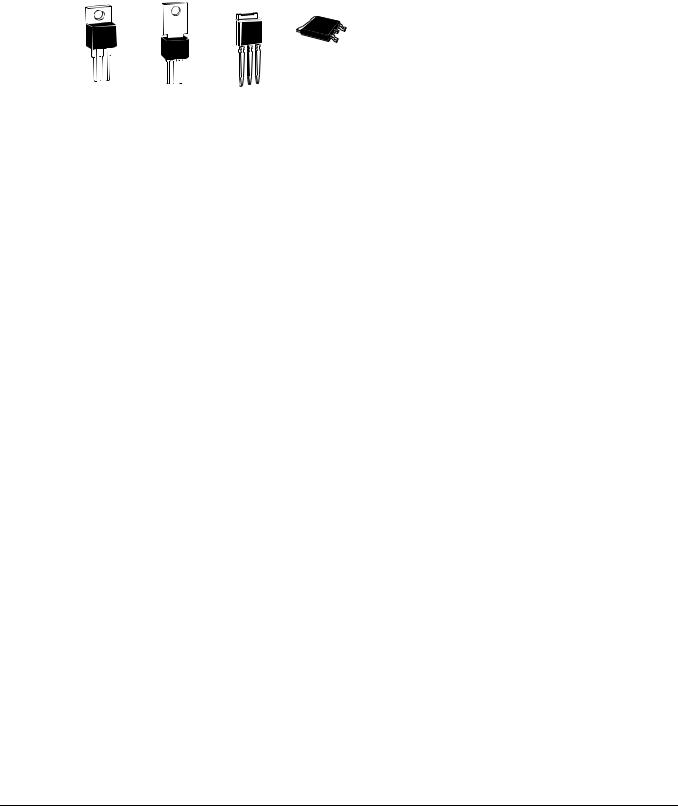
TO-92
*TO-220
Isolated
3-lead Compak
TO-202
TO-252 |
TO-251 |
A |
K |
V-Pak |
|
|
|
D-Pak |
|
|
|
|
|
|
G |
General Description
The Teccor line of sensitive SCR semiconductors are half-wave unidirectional, gate-controlled rectifiers (SCR-thyristor) which complement Teccor's line of power SCRs. This group of packages offers ratings of 0.8 A to 10 A, and 200 V to 600 V with gate sensitivities of 12 µA to 500 µA. For gate currents in the 10 mA to 50 mA ranges, see “SCRs” section of this catalog.
The TO-220 and TO-92 are electrically isolated where the case or tab is internally isolated to allow the use of low-cost assembly and convenient packaging techniques.
Teccor's line of SCRs features glass-passivated junctions to ensure long-term device reliability and parameter stability. Teccor's glass offers a rugged, reliable barrier against junction contamination.
Tape-and-reel packaging is available for the TO-92 package. Consult the factory for more information.
Variations of devices covered in this data sheet are available for custom design applications. Consult the factory for more information.
(0.8 A to 10 A)
Features
•Electrically-isolated TO-220 package
•High voltage capability — up to 600 V
•High surge capability — up to 100 A
•Glass-passivated chip
Compak Features
•Surface mount package — 0.8 A series
•New small-profile three-leaded Compak package
•Four gate sensitivities available
•Packaged in embossed carrier tape with 2,500 devices per reel
•Can replace SOT-223
©2002 Teccor Electronics |
E5 - 1 |
http://www.teccor.com |
Thyristor Product Catalog |
|
+1 972-580-7777 |

Sensitive SCRs |
|
|
|
|
|
|
|
|
|
|
|
|
|
|
|
Data Sheets |
||||
|
|
|
|
|
|
|
|
|
|
|
|
|
|
|
|
|
|
|
|
|
|
|
|
|
|
|
|
|
|
|
|
|
|
|
|
|
|
|
|
|
|
|
|
|
|
|
|
Part Number |
|
|
|
|
IT |
VDRM & |
IGT |
|
IDRM & |
|
VTM |
|
||
|
|
|
|
|
|
Non-isolated |
|
|
|
VRRM |
|
IRRM |
|
|
||||||
|
|
|
|
|
|
|
|
|
|
|
|
(1) |
|
(2) (12) |
|
(20) (21) |
|
(3) (10) |
|
|
|
|
|
|
|
A |
A |
|
|
|
|
|
|
|
|
(14) (18) |
|
|
|
|
|
|
|
|
|
|
|
|
|
G |
A |
|
|
|
|
|
|
|
|
|
|
|
|
|
|
|
|
|
|
|
|
G |
|
|
|
|
|
|
|
|
|
|
|
|
TYPE |
|
|
|
|
|
|
|
|
|
|
|
|
|
|
|
|
|
|
|
|
|
|
|
|
|
|
K |
A |
|
|
|
|
|
|
|
|
|
|
|
|
|
|
|
|
|
|
|
|
A |
K |
|
|
|
|
|
|
|
|
|
|
|
|
|
|
A |
|
|
|
|
|
|
|
|
|
|
|
|
|
|
|
|
|
|
|
K |
|
|
|
|
|
|
|
|
|
|
|
|
|
|
|
|
|
|
|
|
|
G |
K |
G |
G |
|
|
|
|
|
|
|
|
|
|
|
|
|
|
|
|
|
|
|
A |
K A |
|
|
|
|
|
|
|
|
|
|
|
|
|
|
|
|
TO-92 |
|
|
TO-251 |
|
|
TO-252 |
|
Amps |
|
|
|
µAmps |
|
|
|
|||
|
|
TO-202 |
V-Pak |
|
Compak |
D-Pak |
|
|
|
|
|
|
|
|||||||
|
|
|
|
|
|
|
|
|
|
|
IT(RMS) |
IT(AV) |
Volts |
µAmps |
TC or TL = |
TC or TL = |
TC or TL = |
Volts |
|
|
|
|
|
See “Package Dimensions” section for variations. (11) |
|
|
|
25 °C |
100 °C |
110 °C |
|
|
|||||||||
|
|
|
|
|
MAX |
MIN |
MAX |
|
MAX |
|
MAX |
|
||||||||
|
|
|
|
|
|
|
|
S2S1 |
|
|
0.8 |
|
0.51 |
200 |
12 |
2 |
|
100 |
1.7 |
|
|
|
|
|
|
|
|
|
S4S1 |
|
|
0.8 |
|
0.51 |
400 |
12 |
2 |
|
100 |
1.7 |
|
|
|
|
|
|
|
|
|
S6S1 |
|
|
0.8 |
|
0.51 |
600 |
12 |
2 |
|
100 |
1.7 |
|
|
|
|
|
|
|
|
|
S2S2 |
|
|
0.8 |
|
0.51 |
200 |
50 |
2 |
|
100 |
1.7 |
|
|
|
|
|
|
|
|
|
S4S2 |
|
|
0.8 |
|
0.51 |
400 |
50 |
2 |
|
100 |
1.7 |
|
|
|
|
|
|
|
|
|
S6S2 |
|
|
0.8 |
|
0.51 |
600 |
50 |
2 |
|
100 |
1.7 |
|
|
|
|
|
|
|
|
|
S2S |
|
|
0.8 |
|
0.51 |
200 |
200 |
2 |
|
100 |
1.7 |
|
|
|
|
|
|
|
|
|
S4S |
|
|
0.8 |
|
0.51 |
400 |
200 |
2 |
|
100 |
1.7 |
|
|
|
|
|
|
|
|
|
S6S |
|
|
0.8 |
|
0.51 |
600 |
200 |
2 |
|
100 |
1.7 |
|
|
|
|
|
|
|
|
|
S2S3 |
|
|
0.8 |
|
0.51 |
200 |
500 |
2 |
|
100 |
1.7 |
|
|
0.8 A |
|
|
|
|
|
|
S4S3 |
|
|
0.8 |
|
0.51 |
400 |
500 |
2 |
|
100 |
1.7 |
|
|
|
|
|
|
|
|
S6S3 |
|
|
0.8 |
|
0.51 |
600 |
500 |
2 |
|
100 |
1.7 |
|
|
|
|
EC103B |
|
|
|
|
|
|
|
0.8 |
|
0.51 |
200 |
200 |
1 |
50 |
|
1.7 |
|
|
|
|
EC103D |
|
|
|
|
|
|
|
0.8 |
|
0.51 |
400 |
200 |
1 |
50 |
|
1.7 |
|
|
|
|
EC103M |
|
|
|
|
|
|
|
0.8 |
|
0.51 |
600 |
200 |
2 |
100 |
|
1.7 |
|
|
|
|
EC103B1 |
|
|
|
|
|
|
|
0.8 |
|
0.51 |
200 |
12 |
1 |
50 |
|
1.7 |
|
|
|
|
EC103D1 |
|
|
|
|
|
|
|
0.8 |
|
0.51 |
400 |
12 |
1 |
50 |
|
1.7 |
|
|
|
|
EC103M1 |
|
|
|
|
|
|
|
0.8 |
|
0.51 |
600 |
12 |
2 |
100 |
|
1.7 |
|
|
|
|
EC103B2 |
|
|
|
|
|
|
|
0.8 |
|
0.51 |
200 |
50 |
1 |
50 |
|
1.7 |
|
|
|
|
EC103D2 |
|
|
|
|
|
|
|
0.8 |
|
0.51 |
400 |
50 |
1 |
50 |
|
1.7 |
|
|
|
|
EC103M2 |
|
|
|
|
|
|
|
0.8 |
|
0.51 |
600 |
50 |
2 |
100 |
|
1.7 |
|
|
|
|
EC103B3 |
|
|
|
|
|
|
|
0.8 |
|
0.51 |
200 |
500 |
1 |
50 |
|
1.7 |
|
|
|
|
EC103D3 |
|
|
|
|
|
|
|
0.8 |
|
0.51 |
400 |
500 |
1 |
50 |
|
1.7 |
|
|
|
|
EC103M3 |
|
|
|
|
|
|
|
0.8 |
|
0.51 |
600 |
500 |
2 |
100 |
|
1.7 |
|
|
|
|
2N5064 |
|
|
|
|
|
|
|
0.8 |
|
0.51 |
200 |
200 |
1 |
|
50 |
1.7 |
|
|
|
|
2N6565 |
|
|
|
|
|
|
|
0.8 |
|
0.51 |
400 |
200 |
1 |
|
100 |
1.7 |
|
|
|
1.5 A |
TCR22-4 |
|
|
|
|
|
|
|
1.5 |
|
0.95 |
200 |
200 |
1 |
|
100 |
1.5 |
|
|
|
TCR22-6 |
|
|
|
|
|
|
|
1.5 |
|
0.95 |
400 |
200 |
1 |
|
100 |
1.5 |
|
||
|
|
TCR22-8 |
|
|
|
|
|
|
|
1.5 |
|
0.95 |
600 |
200 |
2 |
|
100 |
1.5 |
|
|
|
|
|
|
T106B1 |
|
|
|
|
|
4 |
|
2.5 |
200 |
200 |
2 |
|
100 |
2.2 |
|
|
|
|
|
|
T106D1 |
|
|
|
|
|
4 |
|
2.5 |
400 |
200 |
2 |
|
100 |
2.2 |
|
|
|
|
|
|
T106M1 |
|
|
|
|
|
4 |
|
2.5 |
600 |
200 |
2 |
|
100 |
2.2 |
|
|
|
|
|
|
T107B1 |
|
|
|
|
|
4 |
|
2.5 |
200 |
500 |
2 |
|
100 |
2.5 |
|
|
|
4 A |
|
|
T107D1 |
|
|
|
|
|
4 |
|
2.5 |
400 |
500 |
2 |
|
100 |
2.5 |
|
|
|
|
|
|
T107M1 |
|
|
|
|
|
4 |
|
2.5 |
600 |
500 |
2 |
|
100 |
2.5 |
|
|
|
|
|
|
|
|
S2004VS1 |
|
|
S2004DS1 |
|
4 |
|
2.5 |
200 |
50 |
2 |
|
100 |
1.6 |
|
|
|
|
|
|
|
S4004VS1 |
|
|
S4004DS1 |
|
4 |
|
2.5 |
400 |
50 |
2 |
|
100 |
1.6 |
|
|
|
|
|
|
|
S6004VS1 |
|
|
S6004DS1 |
|
4 |
|
2.5 |
600 |
50 |
2 |
|
100 |
1.6 |
|
|
|
|
|
|
|
S2004VS2 |
|
|
S2004DS2 |
|
4 |
|
2.5 |
200 |
200 |
2 |
|
100 |
1.6 |
|
|
|
|
|
|
|
S4004VS2 |
|
|
S4004DS2 |
|
4 |
|
2.5 |
400 |
200 |
2 |
|
100 |
1.6 |
|
|
|
|
|
|
|
S6004VS2 |
|
|
S6004DS2 |
|
4 |
|
2.5 |
600 |
200 |
2 |
|
100 |
1.6 |
|
|
|
|
|
|
|
|
|
|
|
|
|
|
|
|
|
|
|
|
|
|
See “General Notes” on page E5 - 4 and “Electrical Specifications Notes” on page E5 - 5
http://www.teccor.com |
E5 - 2 |
©2002 Teccor Electronics |
+1 972-580-7777 |
|
Thyristor Product Catalog |

Data Sheets |
|
|
|
|
|
|
|
|
|
|
|
|
Sensitive SCRs |
|||||
|
|
|
|
|
|
|
|
|
|
|
|
|
|
|
|
|
|
|
. |
|
|
|
|
|
|
|
|
|
|
|
|
|
|
|
|
|
|
|
|
|
VGT |
|
|
IH |
IGM |
VGRM |
PGM |
PG(AV) |
ITSM |
dv/dt |
di/dt |
tgt |
tq |
l2t |
|
|
|
|
(4) (12) (22) |
|
|
(5) (15) |
(17) |
|
(17) |
|
(6) (7) (13) |
|
|
|
(8) |
(9) |
|
|
|
|
|
|
|
|
|
(16) (19) |
|
|
|
|
|
|
|
|
|
|
|
|
|
|
|
Volts |
|
|
|
|
|
|
|
Amps |
|
|
|
|
|
|
|
|
TC or TL = |
TC or TL = |
TC or TL |
= |
mAmps |
Amps |
Volts |
Watts |
Watts |
60/50 Hz |
Volts/µSec |
Amps/µSec |
µSec |
µSec |
Amps2/Sec |
|
||
|
-40 °C |
|
25 °C |
110 °C |
|
|
||||||||||||
|
|
MAX |
|
|
MAX |
|
MIN |
|
|
|
MIN |
TYP (23) |
|
TYP |
MAX |
|
|
|
|
1.2 |
|
0.8 |
0.2 |
|
5 |
1 |
5 |
1 |
0.1 |
20/16 |
20 |
|
50 |
2 |
60 |
1.6 |
|
|
1.2 |
|
0.8 |
0.2 |
|
5 |
1 |
5 |
1 |
0.1 |
20/16 |
20 |
|
50 |
2 |
60 |
1.6 |
|
|
1.2 |
|
0.8 |
0.2 |
|
5 |
1 |
5 |
1 |
0.1 |
20/16 |
10 |
|
50 |
2 |
60 |
1.6 |
|
|
1.2 |
|
0.8 |
0.25 |
|
5 |
1 |
5 |
1 |
0.1 |
20/16 |
25 |
|
50 |
3 |
60 |
1.6 |
|
|
1.2 |
|
0.8 |
0.25 |
|
5 |
1 |
5 |
1 |
0.1 |
20/16 |
25 |
|
50 |
3 |
60 |
1.6 |
|
|
1.2 |
|
0.8 |
0.25 |
|
5 |
1 |
5 |
1 |
0.1 |
20/16 |
10 |
|
50 |
3 |
60 |
1.6 |
|
|
1.2 |
|
0.8 |
0.25 |
|
5 |
1 |
5 |
1 |
0.1 |
20/16 |
30 |
|
50 |
4 |
50 |
1.6 |
|
|
1.2 |
|
0.8 |
0.25 |
|
5 |
1 |
5 |
1 |
0.1 |
20/16 |
30 |
|
50 |
4 |
50 |
1.6 |
|
|
1.2 |
|
0.8 |
0.25 |
|
5 |
1 |
5 |
1 |
0.1 |
20/16 |
15 |
|
50 |
4 |
50 |
1.6 |
|
|
1.2 |
|
0.8 |
0.25 |
|
8 |
1 |
5 |
1 |
0.1 |
20/16 |
40 |
|
50 |
5 |
45 |
1.6 |
|
|
1.2 |
|
0.8 |
0.25 |
|
8 |
1 |
5 |
1 |
0.1 |
20/16 |
40 |
|
50 |
5 |
45 |
1.6 |
|
|
1.2 |
|
0.8 |
0.25 |
|
8 |
1 |
5 |
1 |
0.1 |
20/16 |
20 |
|
50 |
5 |
45 |
1.6 |
|
|
1.2 |
|
0.8 |
0.25 |
|
5 |
1 |
5 |
1 |
0.1 |
20/16 |
30 |
|
50 |
3.5 |
50 |
1.6 |
|
|
1.2 |
|
0.8 |
0.25 |
|
5 |
1 |
5 |
1 |
0.1 |
20/16 |
30 |
|
50 |
3.5 |
50 |
1.6 |
|
|
1.2 |
|
0.8 |
0.25 |
|
5 |
1 |
5 |
1 |
0.1 |
20/16 |
15 |
|
50 |
3.5 |
50 |
1.6 |
|
|
1.2 |
|
0.8 |
0.2 |
|
5 |
1 |
5 |
1 |
0.1 |
20/16 |
20 |
|
50 |
2 |
60 |
1.6 |
|
|
1.2 |
|
0.8 |
0.2 |
|
5 |
1 |
5 |
1 |
0.1 |
20/16 |
20 |
|
50 |
2 |
60 |
1.6 |
|
|
1.2 |
|
0.8 |
0.2 |
|
5 |
1 |
5 |
1 |
0.1 |
20/16 |
10 |
|
50 |
2 |
60 |
1.6 |
|
|
1.2 |
|
0.8 |
0.25 |
|
5 |
1 |
5 |
1 |
0.1 |
20/16 |
25 |
|
50 |
3 |
60 |
1.6 |
|
|
1.2 |
|
0.8 |
0.25 |
|
5 |
1 |
5 |
1 |
0.1 |
20/16 |
25 |
|
50 |
3 |
60 |
1.6 |
|
|
1.2 |
|
0.8 |
0.25 |
|
5 |
1 |
5 |
1 |
0.1 |
20/16 |
10 |
|
50 |
3 |
60 |
1.6 |
|
|
1.2 |
|
0.8 |
0.25 |
|
8 |
1 |
5 |
1 |
0.1 |
20/16 |
40 |
|
50 |
5 |
45 |
1.6 |
|
|
1.2 |
|
0.8 |
0.25 |
|
8 |
1 |
5 |
1 |
0.1 |
20/16 |
40 |
|
50 |
5 |
45 |
1.6 |
|
|
1.2 |
|
0.8 |
0.25 |
|
8 |
1 |
5 |
1 |
0.1 |
20/16 |
20 |
|
50 |
5 |
45 |
1.6 |
|
|
1.2 |
|
0.8 |
0.25 |
|
5 |
1 |
5 |
1 |
0.1 |
20/16 |
25 |
|
50 |
2.2 |
60 |
1.6 |
|
|
1.2 |
|
0.8 |
0.25 |
|
5 |
1 |
6 |
1 |
0.1 |
20/16 |
25 |
|
50 |
2.2 |
60 |
1.6 |
|
|
1 |
|
0.8 |
0.25 |
|
5 |
1 |
6 |
1 |
0.1 |
20/16 |
60 |
|
50 |
3.5 |
50 |
1.6 |
|
|
1 |
|
0.8 |
0.25 |
|
5 |
1 |
6 |
1 |
0.1 |
20/16 |
40 |
|
50 |
3.5 |
50 |
1.6 |
|
|
1 |
|
0.8 |
0.25 |
|
5 |
1 |
6 |
1 |
0.1 |
20/16 |
30 |
|
50 |
3.5 |
50 |
1.6 |
|
|
1 |
|
0.8 |
0.2 |
|
5 |
1 |
6 |
1 |
0.1 |
20/16 |
|
8 |
50 |
4 |
50 |
1.6 |
|
|
1 |
|
0.8 |
0.2 |
|
5 |
1 |
6 |
1 |
0.1 |
20/16 |
|
8 |
50 |
4 |
50 |
1.6 |
|
|
1 |
|
0.8 |
0.2 |
|
5 |
1 |
6 |
1 |
0.1 |
20/16 |
|
8 |
50 |
4 |
50 |
1.6 |
|
|
1 |
|
0.8 |
0.2 |
|
6 |
1 |
6 |
1 |
0.1 |
20/16 |
|
8 |
50 |
5 |
45 |
1.6 |
|
|
1 |
|
0.8 |
0.2 |
|
6 |
1 |
6 |
1 |
0.1 |
20/16 |
|
8 |
50 |
5 |
45 |
1.6 |
|
|
1 |
|
0.8 |
0.2 |
|
6 |
1 |
6 |
1 |
0.1 |
20/16 |
|
8 |
50 |
5 |
45 |
1.6 |
|
|
1 |
|
0.8 |
0.2 |
|
4 |
1 |
6 |
1 |
0.1 |
30/25 |
|
8 |
50 |
3 |
50 |
3.7 |
|
|
1 |
|
0.8 |
0.2 |
|
4 |
1 |
6 |
1 |
0.1 |
30/25 |
|
8 |
50 |
3 |
50 |
3.7 |
|
|
1 |
|
0.8 |
0.2 |
|
4 |
1 |
6 |
1 |
0.1 |
30/25 |
|
8 |
50 |
3 |
50 |
3.7 |
|
|
1 |
|
0.8 |
0.2 |
|
6 |
1 |
6 |
1 |
0.1 |
30/25 |
|
8 |
50 |
4 |
50 |
3.7 |
|
|
1 |
|
0.8 |
0.2 |
|
6 |
1 |
6 |
1 |
0.1 |
30/25 |
|
8 |
50 |
4 |
50 |
3.7 |
|
|
1 |
|
0.8 |
0.2 |
|
6 |
1 |
6 |
1 |
0.1 |
30/25 |
|
8 |
50 |
4 |
50 |
3.7 |
|
|
|
|
|
|
|
|
|
|
|
|
|
|
|
|
|
|
|
|
See “General Notes” on page E5 - 4 and “Electrical Specifications Notes” on page E5 - 5
©2002 Teccor Electronics |
E5 - 3 |
http://www.teccor.com |
Thyristor Product Catalog |
|
+1 972-580-7777 |
Sensitive SCRs |
|
|
|
|
|
|
|
|
|
|
|
|
|
Data Sheets |
||||
|
|
|
|
|
|
|
|
|
|
|
|
|
|
|
|
|
|
|
|
|
|
|
|
|
|
|
|
|
|
|
|
|
|
|
|
|
|
|
|
|
|
|
|
Part Number |
|
|
IT |
|
VDRM & |
IGT |
IDRM & |
VTM |
|
|||
|
|
|
Isolated |
|
|
Non-isolated |
|
|
|
VRRM |
IRRM |
|
||||||
|
|
|
|
|
|
|
|
|
|
(1) |
|
|
(2) (12) |
(20) (21) |
(3) (10) |
|
||
|
|
|
|
|
|
A |
A |
|
|
|
|
|
|
|
|
|
|
|
|
|
|
|
|
|
|
|
A |
G |
|
|
|
|
|
|
|
|
|
|
|
|
|
|
|
|
|
|
|
|
|
|
|
|
|
|
|
|
|
TYPE |
|
|
|
|
|
|
|
A |
|
|
|
|
|
|
|
|
|
|
|
|
|
|
|
|
K |
|
|
|
|
|
|
|
|
|
|
|
|
|
|
K |
G |
K |
G |
G |
|
|
|
|
|
|
|
|
|
|
|
|
|
|
|
A |
|
A |
K A |
|
|
|
|
|
|
|
|
|
|
|
|
|
|
|
|
|
|
TO-251 |
TO-252 |
|
Amps |
|
|
µAmps |
|
|
|||
|
|
|
TO-220 |
|
TO-202 |
V-Pak |
D-Pak |
|
|
|
|
|
||||||
|
|
|
|
|
|
|
|
|
|
|
|
|
|
|||||
|
|
|
|
|
|
|
|
|
|
IT(RMS) |
|
|
Volts |
µAmps |
TC = |
TC = |
Volts |
|
|
|
|
|
See “Package Dimensions” section for variations. (11) |
|
|
IT(AV) |
25 °C |
110 °C |
|
||||||||
|
|
|
|
|
MAX |
|
MAX |
MIN |
MAX |
MAX |
MAX |
MAX |
|
|||||
|
|
|
S2006LS2 |
S2006FS21 |
S2006VS2 |
S2006DS2 |
6 |
|
3.8 |
200 |
200 |
5 |
250 |
1.6 |
|
|||
|
6 A |
|
S4006LS2 |
S4006FS21 |
S4006VS2 |
S4006DS2 |
6 |
|
3.8 |
400 |
200 |
5 |
250 |
1.6 |
|
|||
|
|
S6006LS2 |
S6006FS21 |
S6006VS2 |
S6006DS2 |
6 |
|
3.8 |
600 |
200 |
5 |
250 |
1.6 |
|
||||
|
|
|
S2006LS3 |
S2006FS31 |
S2006VS3 |
S2006DS3 |
6 |
|
3.8 |
200 |
500 |
5 |
250 |
1.6 |
|
|||
|
|
|
S4006LS3 |
S4006FS31 |
S4006VS3 |
S4006DS3 |
6 |
|
3.8 |
400 |
500 |
5 |
250 |
1.6 |
|
|||
|
|
|
S6006LS3 |
S6006FS31 |
S6006VS3 |
S6006DS3 |
6 |
|
3.8 |
600 |
500 |
5 |
250 |
1.6 |
|
|||
|
|
|
S2008LS2 |
S2008FS21 |
S2008VS2 |
S2008DS2 |
8 |
|
5.1 |
200 |
200 |
5 |
250 |
1.6 |
|
|||
|
|
|
S4008LS2 |
S4008FS21 |
S4008VS2 |
S4008DS2 |
8 |
|
5.1 |
400 |
200 |
5 |
250 |
1.6 |
|
|||
|
8 A |
|
S6008LS2 |
S6008FS21 |
S6008VS2 |
S6008DS2 |
8 |
|
5.1 |
600 |
200 |
5 |
250 |
1.6 |
|
|||
|
|
S2008LS3 |
S2008FS31 |
S2008VS3 |
S2008DS3 |
8 |
|
5.1 |
200 |
500 |
5 |
250 |
1.6 |
|
||||
|
|
|
|
|
||||||||||||||
|
|
|
S4008LS3 |
S4008FS31 |
S4008VS3 |
S4008DS3 |
8 |
|
5.1 |
400 |
500 |
5 |
250 |
1.6 |
|
|||
|
|
|
S6008LS3 |
S6008FS31 |
S6008VS3 |
S6008DS3 |
8 |
|
5.1 |
600 |
500 |
5 |
250 |
1.6 |
|
|||
|
|
|
S2010LS2 |
S2010FS21 |
S2010VS2 |
S2010DS2 |
10 |
|
6.4 |
200 |
200 |
5 |
250 |
1.6 |
|
|||
|
|
|
S4010LS2 |
S4010FS21 |
S4010VS2 |
S4010DS2 |
10 |
|
6.4 |
400 |
200 |
5 |
250 |
1.6 |
|
|||
|
10 A |
|
S6010LS2 |
S6010FS21 |
S6010VS2 |
S6010DS2 |
10 |
|
6.4 |
600 |
200 |
5 |
250 |
1.6 |
|
|||
|
|
S2010LS3 |
S2010FS31 |
S2010VS3 |
S2010DS3 |
10 |
|
6.4 |
200 |
500 |
5 |
250 |
1.6 |
|
||||
|
|
|
|
|
||||||||||||||
|
|
|
S4010LS3 |
S4010FS31 |
S4010VS3 |
S4010DS3 |
10 |
|
6.4 |
400 |
500 |
5 |
250 |
1.6 |
|
|||
|
|
|
S6010LS3 |
S6010FS31 |
S6010VS3 |
S6010DS3 |
10 |
|
6.4 |
600 |
500 |
5 |
250 |
1.6 |
|
|||
|
|
|
|
|
|
|
|
|
|
|
|
|
|
|
|
|
|
|
Specific Test Conditions
di/dt — Maximum rate-of-change of on-state current; IGT = 50 mA pulse width 15 µsec with 0.1 µs rise time
dv/dt — Critical rate-of-rise of forward off-state voltage
I2t — RMS surge (non-repetitive) on-state current for period of 8.3 ms for fusing
IDRM and IRRM — Peak off-state current at VDRM and VRRM IGT — DC gate trigger current VD = 6 V dc; RL = 100 IGM — Peak gate current
IH — DC holding current; initial on-state current = 20 mA IT — Maximum on-state current
ITSM — Peak one-cycle forward surge current PG(AV) — Average gate power dissipation PGM — Peak gate power dissipation
tgt — Gate controlled turn-on time gate pulse = 10 mA; minimum width = 15 µS with rise time 0.1 µs
tq — Circuit commutated turn-off time
VDRM and VRRM — Repetitive peak off-state forward and reverse voltage VGRM — Peak reverse gate voltage
VGT — DC gate trigger voltage; VD = 6 V dc; RL = 100 VTM — Peak on-state voltage
General Notes
•Teccor 2N5064 and 2N6565 Series devices conform to all JEDEC registered data. See specifications table on pages E5 - 2 and
E5 - 3.
•The case lead temperature (TC or TL) is measured as shown on dimensional outline drawings in the “Package Dimensions” section of this catalog.
•All measurements (except IGT) are made with an external resistor RGK = 1 k unless otherwise noted.
•All measurements are made at 60 Hz with a resistive load at an ambient temperature of +25 °C unless otherwise specified.
•Operating temperature (TJ) is -65 °C to +110 °C for EC Series devices, -65 °C to +125 °C for 2N Series devices, -40 °C to +125 °C for “TCR” Series, and -40 °C to +110 °C for all others.
•Storage temperature range (TS) is -65 °C to +150 °C for TO-92 devices, -40 °C to +150 °C for TO-202 and Compak devices, and -40 °C to +125 °C for all others.
•Lead solder temperature is a maximum of +230 °C for 10 seconds maximum 1/16" (1.59 mm) from case.
http://www.teccor.com |
E5 - 4 |
©2002 Teccor Electronics |
+1 972-580-7777 |
|
Thyristor Product Catalog |
 Loading...