


Multi-role Digital Camera Head
Manual Operator’s
3922 496 46751 St.01

Declaration of Conformity
We, Thomson Broadcast Solutions Nederland B.V., Kapittelweg 10, 4827 HG Breda, The Netherlands declare under our sole responsibility that this product is in compliance with the following standards:
EN60065 : Safety
EN55103-1 : EMC (Emission) EN55103-2 : EMC (Immunity)
following the provisions of:
a.the Safety Directives 73/23//EEC and 93/68/EEC
b.the EMC Directives 89/336/EEC and 93/68/EEC
FCC Class A Statement
This product generates, uses, and can radiate radio frequency energy and if not installed and used in accordance with the instructions, may cause interference to radio communications.
It has been tested and found to comply with the limits for a class A computing device pursuant to Subpart J of part 15 of FCC rules, which are designed to provide reasonable protection against such interference when operated in a commercial environment.
Operation of this product in a residential area is likely to cause interference in which case the user at his own expense will be required to take whatever measures may be required to correct the interference.
Copyright
Für diese Unterlage behalten wir uns alle Rechte vor (Gemäß DIN 34). Technische Änderungen im Zuge der Weiterentwicklung vorbehalten.
Copying of this document and giving it to others, and the use or communication of the contents thereof, are forbidden without express authority. Offenders are liable to the payment of damages. All rights are reserved in the event of the grant of a patent or the registration of a utility model or design. Liable to technical alterations in the course of further development.
© Thomson Multimedia Broadcast Solutions 2002
Toute communication ou reproduction de ce document, toute exploitation ou communication de son contenu sont interdites, sauf autorisation expresse. Tout manquement à cette règle est illicite et expose son auteur au versement de dommages et intérêts. Tous nos droits sont réservés pour le cas de la délivrance d'un modèle d'utilité. Sous réserve de modification au cours de l'évolution technique.

LDK 100 Triax
Multi-role Digital Camera Head
Operator's Manual
Contents
About this Manual ................................................. |
ii |
Introduction ...................................................... |
1-1 |
Technology ........................................................ |
1-2 |
Smart Card ........................................................ |
1-3 |
Features ............................................................ |
1-4 |
Important Precautions ........................................ |
1-5 |
Assembling the Units ....................................... |
2-1 |
Transport Case .................................................. |
2-2 |
Lens ................................................................... |
2-3 |
1.5-inch Viewfinder ............................................. |
2-4 |
1.5-inch Viewfinder Accessories ........................ |
2-6 |
Microphone ........................................................ |
2-7 |
Tripod Adapter Plate .......................................... |
2-8 |
SuperXPander .................................................... |
2-9 |
Local Control Panel ............................................ |
2-9 |
Shoulder Pad ................................................... |
2-10 |
Rain and Off-use Cover .................................... |
2-11 |
Zoom Controls ................................................. |
2-11 |
Top Light .......................................................... |
2-11 |
Configurations ................................................. |
3-1 |
Basic Configurations .......................................... |
3-2 |
Location of Controls and Functions ............... |
4-1 |
Power Supply ..................................................... |
4-2 |
Security and Access .......................................... |
4-2 |
Audio ................................................................. |
4-3 |
Intercom ............................................................ |
4-3 |
Video Functions ................................................. |
4-4 |
Viewfinder .......................................................... |
4-7 |
Viewfinder Indicators .......................................... |
4-8 |
Control Functions ............................................... |
4-9 |
Shooting ........................................................... |
5-1 |
Using the Camera .............................................. |
5-2 |
Standard settings ............................................... |
5-3 |
Colour Bar .......................................................... |
5-4 |
Gain selection .................................................... |
5-4 |
Optical filter selection ........................................ |
5-4 |
Colour temperature selection .............................. |
5-5 |
Auto-White Balance ........................................... |
5-5 |
Shooting Screens ............................................... |
5-6 |
Exposure Time ................................................... |
5-6 |
Using the Menu System ................................... |
6-1 |
Introduction ........................................................ |
6-2 |
Systems Menu ................................................... |
6-3 |
Appendix ......................................................... |
A-1 |
List of Abbreviations ......................................... |
A-2 |
02.12.1 |
Operator's Manual LDK 100 Camera Head |
i |

About this Manual
This operator's manual is part of a complete documentation set for the camera which also includes a Technical Manual, and a Service Manual.
Purpose of this manual
The purpose of this manual is to present a detailed description of how to operate the LDK 100 Multi-role Camera Head. It provides the information necessary to use the camera in different configurations and with various attachments. With this manual it is possible to discover all the operating features of the camera and so use it to its full potential. The manual should be used together with the camera to explore and learn about the many sophisticated control functions available.
Intended audience
This operator's manual can be used by inexperienced cameraoperatorswhoare newtoThomsonMultimedia Broadcast Solutions cameras as well as those who have previous experience of operating cameras. The guide is so designed that it can be used as an introduction to those who are new to the camera, as a simple procedural guide to those who wish to set-up and start shooting immediately, and as a reference work to be consulted as required during the long life of the camera.
Structure of this manual
Themanualisdividedintosixsectionsandanappendix:
Section 1: Introduction
This section outlines the technology used in the LDK 100 camera and how this translates into a practical, useable camera. It lists the main features of the camera and also the precautions that must be taken into account when using it.
Section 2: Assembling the Units
Section 2 provides information on the physical assembly of the camera and on how accessories can be used to expand the possibilities of the camera. The mounting of accessories and packing for transport is also explained.
Section 3: Configurations
The LDK 100 is a multi-functional camera and this section describes the various ways that it can be used. Information on the cables, control panels and the control bus is also provided as is information on the main video and audio signal paths through the system.
Section 4: Location of Controls and Functions
This section shows the physical location of the controls and connectors on the camera. These are grouped according to their function so as to provide a quick reference guide to the operation of a particular aspect of the camera.
Section 5: Shooting
This section contains information on the practical use of the camera using the viewfinder display and the switches to control the camera.
Section 6: Operating the Menu System
Because the LDK 100 offers such a wide range of functions, this section describes the structure of the control system.
Appendix
The appendix contains a list of Abbreviations used in this manual.
Camera versions
Throughout the manual [FT] refers to functions that are only available for Frame Transfer cameras. [IT] refers to functions that are only available for Interline Transfer cameras.
ii |
Operator's Manual LDK 100 Camera Head |
02.12.1 |

Section 1
Introduction
This section outlines the technology used in the LDK 100 Digital Camera Head and how this translates into a practical, useable camera. It lists the main features of the camera and also the precautions that must be taken into account when using it.
Contents
Technology ........................................................ |
1-2 |
Features ............................................................ |
1-4 |
Smart Card ........................................................ |
1-3 |
Important Precautions ........................................ |
1-5 |
Introduction |
Operator's Manual LDK 100 Camera Head |
1-1 |

Technology
The LDK 100 camera is a multi-role digital camera head using 2/3-inch CCD sensors. This is a flexible camera that is equally at home in the studio or out on location in an OB environment.
Digital Processing
The advanced digital processing of the camera is based on 12-bit A/D converters and more than 20-bit internal processing. Two DSPs combine all major camera functions in the digital domain, including knee, gamma, contour, matrix and colour correction.
The intelligent continuous automatics facility provides automatic control of black levels and black shading. Each sensor provides black reference signals that are used to monitor temperature changes. This means that continuous automatic correction is applied without operator intervention.
The digital contour processing uses full amplitude video RGB signals via an extended dynamic range contour circuit.
Colorimetry is selected by means of a variable 6-point digital matrix or via preset matrices. Digital gamma circuits provide a wide range of standardised gamma curves and enable soft contrast in black scenes to be enhanced, together with hard contrast and saturated colour in bright scenes. The matrix and gamma sequence is software programmable for precise colour matching.
Film-like characteristics
The pivoting knee circuit adapts both the knee point and the compression ratio according to the highlight content of the picture to emulate the softly limiting S- shaped transfer characteristics of film. Digital True Colour Knee circuitry maintains the correct hue for compressed highlights, reproducing colours faithfully, even overexposed skin tones.
Digital contrast circuitry provides a black stretch function for more detail in black areas and a black press function for improving the contrast impression by simulating the S-curve of film.
SuperXPander
An optional SuperXpander enables the camera to be used with large lenses so extending the camera's use in studio and EFP situations.
Camera Head Versions
The camera head can be supplied in three different versions depending on the type of sensor required.
The Frame Transfer CCD sensor version offers superior performance and can handle highlights of up to 600%. The 2/3-inch sensors have a high dynamic range and high linear sensitivity over all camera lens apertures. Frame Transfer technology ensures that there is no lag nor smear.
The Frame Transfer DPM version uses Dynamic Pixel Management which allows the format of the sensors to be switched between 4:3 and 16:9 aspect ratios at the touch of a switch without loss of horizontal or vertical resolution. The 1000 pixels per line in both formats ensures that there is no loss in the horizontal viewing angle but also ensures high resolution in the red, green and blue channels.
The Interline Transfer sensor version is a very costeffective camcorder that still provides superior digital signal processing.
The Interline Transfer Wide (ITW) Switchable sensor version is fitted with switchable aspect ratio IT CCD sensors.Thisversionenablestheformatofthesensors to be switched between 4:3 and 16:9 aspect ratios at the touch of a switch. Aspect ratio switching to 4:3 ratio is achieved by activating two horizontal side panels.
1-2 |
Operator's Manual LDK 100 Camera Head |
Introduction |
Smart Card
Three smart cards are delivered with each camera. These comprise of two user cards and one owner card.
The owner's smart card has three functions:
•As an access control device to the security settings of the camera.
•As a storage device for four scene files.
•As a storage device for two operator files.
The owner card is unique to every camera. Owner card and camera must have the same serial number.
The user smart card has two functions:
•As a storage device for four scene files.
•As a storage device for two operator files.
Access control
The owner card is used to set the user level. There are four user levels present in the camera. These restrict access, in varying degrees, to the operational controls. The Appendix indicates which functions are available at each user level. (The owner card also gives access to a service level; refer to the Technical Manual for more information about this level.)
|
|
Made in Holland |
TYPE |
OWNER CARD |
|
FACT/NC |
3922 |
407 24981 |
SERIAL NR. |
5038 |
|
Use waterproof marker or pencil to fill in
COMPANY:
USER:
DATE:
SCENE FILE
OPERATOR FILE
Printed by DocuCards, The Netherlands
Scene files
Both the user card and the owner card allow four different scene files to be stored on the card. The recall and storage of a scene file is carried out via the Files menu of the menu system. A scene file contains information relating to the video settings.
Operator files
Both the user card and the owner card allow two different operator files to be stored on the card. The recall and storage of a operator file is carried out via the Files menu of the menu system. An operator file contains information relating to the set-up of general camera preferences.
Note
Only use an original Thomson camera card. Store the owner card in a safe place.
LDK 100
User card
Use waterproof marker or pencil to fill in
COMPANY:
USER:
DATE:
SCENE FILE
OPERATOR FILE
Printed by DocuCards, The Netherlands
Owner card |
User card |
Introduction |
Operator's Manual LDK 100 Camera Head |
1-3 |

Features
•12-bit digital processing with unique software programmable video path.
•Superior all digital highlight handling with a wide dynamic.
•Unique circuitry for pivoting knee and True Colour Knee.
•Wide range of presets and variable 6-point digital matrix assure accurate colour matching.
•Fluorescent light matrix
•Digital gamma with unique standard preset values and highest accuracy.
•Digital contour with an extensive range of parameters.
•Advanced contour correction includes two automatic skin settings.
•Intelligent Continuous Automatics black levels, black shading and video levels - no set-up time required.
•Digital contrast with standard black stretch and black press.
•International standard 2/3-inch lens interface.
•4-position standard filter wheel.
•Electronic colour filter can be used for creating a special look (warm / cold) of a scene, or for a smooth colour temperature control around the white balance setting.
•Smart card for personal settings and security.
•Owner card for setting user levels, and for copying and storing control settings.
•Protected, easy-to-operate controls and switches with read-out of all settings.
•Viewfinder status read-out of primary camera functions.
•Clean scan feature allows capture of computer and other monitor pictures.
•Digital RS 232 interface to PC.
Options
•Zoom control handgrip makes awkward shots easy.
•Transport case.
•SuperXPander extends the camera's use in studio and EFP situations.
•Smart-Touch™ gives the operator instant, onebutton access to 14 predefined shooting characteristics.
Frame Transfer version
•3 x 2/3-inch Philips Frame Transfer CCD sensors ensure no vertical smear.
•Dynamic range of up to 600%.
DPM version
•3x 2/3-inch switcheable DPM sensors ensure no vertical smear.
•DPM Frame Transfer sensors with 1000 horizontal pixels in 4:3 and 16:9 aspect ratios, and the same number of vertical lines in both formats. No change in horizontal viewing angle - so no optical wide angle convertors required.
Interline Transfer version
•3 x 2/3-inch Interline Transfer CCD sensors.
•Dynamic range of up to 500%.
Interline Transfer Wide Switchable version
•3x 2/3-inch Interline Transfer Wide Switchable low smear CCD sensors.
1-4 |
Operator's Manual LDK 100 Camera Head |
Introduction |
Important Precautions
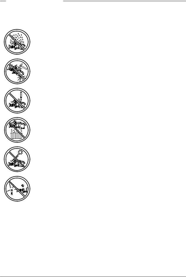
To ensure continual high performance from the camera take the following precautions into consideration:
Avoid very damp places. If the environment is wet or damp a rain cover must be used to protect the unit.
Do not subject the unit to severe shocks or vibration.
Do not expose the camera to extremes of temperature.
Do not leave the unit in direct sunlight or close to heating appliances for extended periods.
Do not allow sunlight to shine into the viewfinder.
Avoid extreme highlights as these can cause various kinds of optical 


 reflections.
Warnings
If the unit is in a wet or damp environment, a rain cover must be used to protect it for personal safety reasons (EN60065). The rain cover supplied with the unit protects it according to safety specification EN60529 up to level IPX2 (spraying water).
FCC Class A Statement
This equipment generates, uses, and can radiate radio frequency energy and if not installed and used in accordance with the instructions, may cause interference to radio communications.
It has been tested and found to comply with the limits for a class A computing device pursuant to Subpart J of part 15 of FCC rules, which are designed to provide reasonable protection against such interference when operated in a commercial environment.
Operation of this equipment in a residential area is likely to cause interference in which case the user at his own expense will be required to take whatever measures may be required to correct the interference.
Introduction |
Operator's Manual LDK 100 Camera Head |
1-5 |

1-6 |
Operator's Manual LDK 100 Camera Head |
Introduction |
Section 2
Assembling the Units
Section 2 provides information on the physical assembly of the camera and on how accessories can be used to expand the possibilities of the camera. The mounting of accessories and packing for transport are also explained.
Contents
Transport Case .................................................. |
2-2 |
SuperXPander .................................................... |
2-9 |
Lens ................................................................... |
2-3 |
Local Control Panel ............................................ |
2-9 |
1.5-inch Viewfinder ............................................. |
2-4 |
Shoulder Pad ................................................... |
2-10 |
1.5-inch Viewfinder Accessories ........................ |
2-6 |
Rain and Off-use Cover .................................... |
2-11 |
Microphone ........................................................ |
2-7 |
Zoom Controls ................................................. |
2-11 |
Tripod Adapter Plate .......................................... |
2-8 |
Top Light .......................................................... |
2-11 |
Assembling the Units |
Operator’s Manual LDK 100 Camera Head |
2-1 |
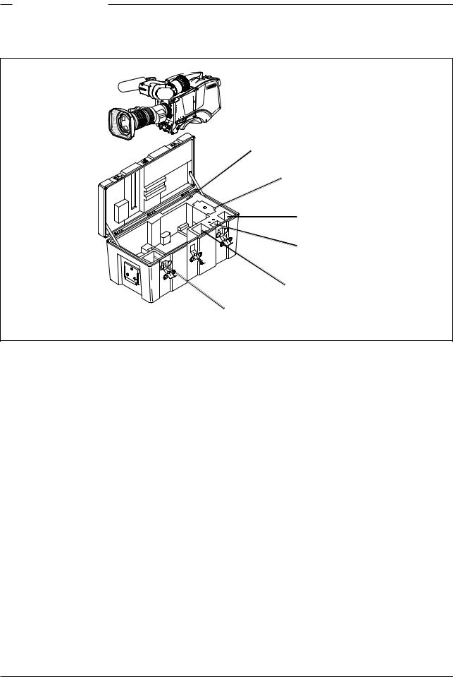
Transport Case
Documentation
Packing inserts
Top light
Tripod Plate
Battery
Additional
Supplies
It is important to protect your camera against damage when transporting it. To do this, a transport case (LDK 5020/00) is optionally available for the camera, lens, viewfinder and some accessories.
The camera is packed in the transport case as shown in the figure above. This ensures that the camera is not damaged during transport.
Turn the 1.5-inch viewfinder downwards so that it does not protrude above the top of the camera.
Several foam packing inserts are provided to enable different configurations of the camera to be packed securely. These inserts are used to support the rear of the camera. Make sure you use the correct foam insert for your particular configuration.
2-2 |
Operator’s Manual LDK 100 Camera Head |
Assembling the Units |
Lens |
|
|
1 |
|
2 |
4 |
|
|
bts1009 |
5 |
3 |
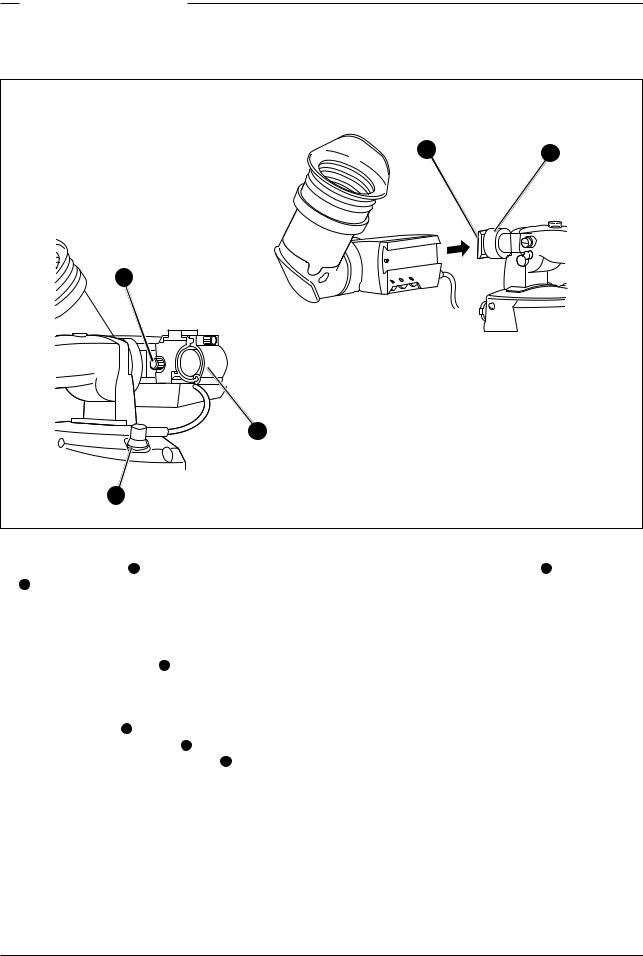
To attach a lens to the camera head proceed as follows:
a.Ensure that the lens locking ring 1 is in the unlocked position - turned counterclockwise.
b. Remove the dust protection |
2 . |
c.Slot the lens into the lens mount 3 .
d.Turn the lens locking ring 1 clockwise to lock the lens in place.
e.Connect the lens cable to the lens connector 4 at the right side of the camera.
f.Place the lens cable into the bottom clip at the front of the camera and clip 5 located at the side. (Pull
and twist clip 5 to open it.)
Caution
Do not attach a lens weighting more than 5 kg to the camera without a support.
Note
Always mount the dust protection cap when the lens is not connected to the camera.
When a new lens is fitted to the camera it may be necessary to carry out some adjustments to optimize its use, for example, back focus or shading. For more information about these adjustments refer to Section 5 and to the lens manufacturer’s documentation.
Assembling the Units |
Operator’s Manual LDK 100 Camera Head |
2-3 |
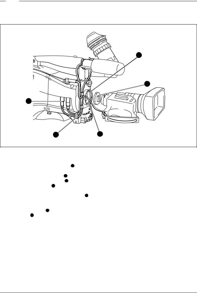
1.5-inch Viewfinder
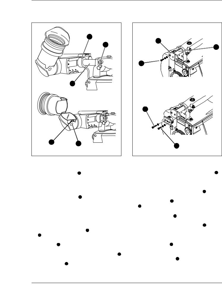
Mounting the 1.5-inch viewfinder and microphone holder
2 |
1 |
5
4
3
To mount the 1.5-inch viewfinder proceed as follows: a. locking ring 1 of viewfinder support bracket 2 at the front of the camera handle. (As seen from the rear of the camera, turning the locking ring counterclockwise moves it towards the handle.)
b.Slide the viewfinder onto the viewfinder support bracket.
c.Tighten the locking ring 1 by turning it clockwise (as seen from rear) so that the viewfinder is mounted securely to the support.
d.Connect the viewfinder cable to the viewfinder connector socket 3 at the top right of the camera.
e.Slide the microphone holder 4 onto the viewfinder and secure with the knurled screw 5 .
Caution
Always fit the microphone holder 4 as it functions as a safety stop for the viewfinder.
f.To improve the comfort of the skin contact when using the viewfinder, fit the soft cover to the rubber eyepiece.
2-4 |
Operator’s Manual LDK 100 Camera Head |
Assembling the Units |
Positioning the 1.5-inch viewfinder
|
1 |
|
2 |
|
3 |
5 |
4 |
|
Thehorizontalpositionoftheviewfindercanbeadjusted as follows to suit your requirements:
a.Loosen the locking ring 1 . (As seen from the rear of the camera, turning the locking ring counterclockwise moves it towards the handle.)
b.Slide the viewfinder horizontally along the rail to the desired position.
c.Tighten the locking ring 1 by turning clockwise.
Thedioptrehoodandeyepieceoftheviewfindercanbe rotated vertically.
The viewfinder can be positioned backwards and forwards along the camera axis. Loosen the support bracket round bar retaining lever 2 and slide the round bar 3 forwardsorbackwards.Whenthedesiredposition is reached tighten the support bracket round bar retaining lever 2 again.
To use the viewfinder at a distance press the button 4 below or above the eyepiece tube and swing it free of the associated clip 5 . The display can now be seen from further away.
Right eye adapter
6 |
8 |
9 |
10 |
7 |
When wearing headphones it may be necessary to move the viewfinder further to the left to obtain a more comfortable viewing position. A right eye adapter 6 is supplied for this purpose. Mount the right eye adapter as follows:
a.Remove the viewfinder from the support bracket.
b.Unscrew and remove the two screws 7 that hold the bracket in place.
c. Attach the adapter 6 to the end of the sliding tube 8 so that it protrudes to the right (as seen from the front) ensuring that the pins fit snugly into the slots.
d.Use the short screw 9 and the washers supplied with the adapter to secure it to the left hole (as seen from the front) of the sliding bar 8 .
e.Attach the support bracket to the adapter ensuring that the pins fit snugly (if necessary turn locking ring to move it away from the adapter).
f.Use the long screw 10 supplied with the adapter and a washer in the left screw hole to secure the bracket.
g.Use one of the screws 7 and the washer removed at the start to completely secure the bracket.
h.Remount the viewfinder.
Assembling the Units |
Operator’s Manual LDK 100 Camera Head |
2-5 |
 Loading...