


TECHNICAL MANUAL FOR
GENESYSTM 750W HALF RACK
Programmable DC Power Supplies
Document: 83-507-5002 Rev B
TDK-Lambda Americas Inc.
405 Essex Road, Neptune, NJ 07753
Tel: (732) 922-9300
Fax: (732) 922-9334
Web: www.US.TDK-Lambda.com/HP


GENESYS™ Manual Supplement
FOR UNITS EQUIPPED WITH “IEMD” OPTION. ALSO REFER TO MANUAL 83-030-200 IEMD.
83-507-5002 Rev. B

TABLE OF CONTENTS
WARRANTY……………………………………………………………………………………………. |
|
Pg. 1 |
||||||
SAFETY INSTRUCTIONS…………………………………………………………………………….. |
|
Pg. 2 |
||||||
GERMAN SAFETY INSTRUCTIONS………………………………………………………………… |
Pg. 4 |
|||||||
CHAPTER 1 GENERAL INFORMATION…………………………………………………………... |
Pg. 6 |
|||||||
1.1 USER MANUAL CONTENT………………………………………………………………………. |
|
Pg. 6 |
||||||
1.2 INTRODUCTION…………………………………………………………………………………… |
|
Pg. 6 |
||||||
1.2.1 General description………………………………………………………………………… |
.. |
Pg. 6 |
||||||
1.2.2 Models covered ……………………………………………………………… |
|
|
……………... |
Pg. 6 |
||||
1.2.3 Features and options ……………………………………………… |
……………………….. |
Pg. 6 |
||||||
1.2.4 Multiple output power system ………………………… |
………………… |
………………… |
Pg. 7 |
|||||
1.2.5 Control via the serial communication port………………………………………………… |
Pg. 7 |
|||||||
1.2.6 Analog voltage programming and monitoring……………………………………………. |
Pg. 7 |
|||||||
1.2.7 Parallel operation……………………………………………………… |
|
……………………. |
Pg. 7 |
|||||
1.2.8 Output connections…………………………………………………………………………. |
|
Pg. 7 |
||||||
1.2.9 Cooling and mechanical construction………… |
………………………………………….. |
Pg. 8 |
||||||
1.3 ACCESSORIES……………………………………………………………………………………. |
|
Pg. 8 |
||||||
1.3.1 Included Accessories………………………………………………… |
…………………….. |
Pg. 8 |
||||||
1.3.2 Optional Communication Cables…………………….. |
.…………………………………… |
Pg. 8 |
||||||
1.3.3 AC cables …………………………………………………………………………… |
|
………. |
Pg. 8 |
|||||
CHAPTER 2 SPECIFICATIONS……………………………………………………………………... |
Pg. 9 |
|||||||
2.1 OUTPUT RATING……… …………………………………………………………………………. |
|
Pg. 9 |
||||||
2.2 INPUT CHARACTERISTICS…………………………………………………………………… |
... |
Pg. 9 |
||||||
2.3 CONSTANT VOLTAGE MODE…………………………………………………………………. |
.. |
Pg. 9 |
||||||
2.4 CONSTANT CURRENT MODE…………………………………………………………………. |
. |
Pg. 9 |
||||||
2.5 ANALOG PROGRMAMING AND MONITORING………………………………………………. |
Pg. 9 |
|||||||
2.6 PROGRAMMING AND READBACK…………………………………………………………… |
.. |
Pg. 10 |
||||||
2.7 PROTECTIVE FUNCTIONS……………………………………………………………………… |
|
Pg. 10 |
||||||
2.8 FRONT PANEL……………………………………………………………………………………. |
|
Pg. 10 |
||||||
2.9 ENVIRONMENTAL CONDITIONS……………………………………………………… |
………. |
Pg. 10 |
||||||
2.10 MECHANICAL……………………………………………………………………………………. |
|
Pg. 10 |
||||||
2.11 SAFETY/EMC…………………………………………………………………………………….. |
|
Pg. 10 |
||||||
2.12 SUPPLEMENTAL CHARACTERISTICS……………………………………………… |
………. |
Pg. 11 |
||||||
2.13 OUTLINE DRAWINGS………………………………………………………………………….. |
. |
Pg. 12 |
||||||
CHAPTER 3 INSTALLATION………………………………………………………………………. |
|
|
|
|
|
. |
Pg. 13 |
|
3.1 GENERAL…………………………………………………………………………………………... |
|
Pg. 13 |
||||||
3.2 PREPARATION FOR USE………………………………………………………………………. |
.. |
Pg. 13 |
||||||
3.3 INITIAL INSPECTION…………………………………………………………………………… |
... |
Pg. 13 |
||||||
3.4 RACK MOUNTING………………………………………………………………………………… |
|
Pg. 14 |
||||||
3.4.1 Single-unit installation………………………..…………………………………………….. |
|
Pg. 14 |
||||||
3.4.2 Dual unit installation………..………………………………………………………………. |
|
Pg. 14 |
||||||
3.4.3 GENH/RM Rack Mounting outline drawings.……………………… |
……………………. |
Pg. 15 |
||||||
3.5 LOCATION MOUNTING AND COOLING……………………………………………… |
………. |
Pg. 15 |
||||||
3.6 AC SOURCE REQUIREMENTS………………………………………………………………… |
. |
Pg. 15 |
||||||
3.7 AC INPUT POWER CONNECTION………………………………………………………… |
…... |
Pg. 15 |
||||||
3.7.1 AC input connector………………….………………………… |
|
…………………………… |
Pg. 16 |
|||||
3.7.2 AC input cord………………………………………………………………… |
|
|
…………….. |
Pg. 16 |
||||
3.8 TURN-ON CHECKOUT PROCEDURE…………………………………………………………. |
Pg. 16 |
|||||||
3.8.1 General………………………………………………………………………………… |
|
……. |
Pg. 16 |
|||||
3.8.2 Prior to operation………………………………… |
…………………………………………. |
Pg. 16 |
||||||
3.8.3 Constant voltage check………………………………………… |
………………………….. |
Pg. 17 |
||||||
3.8.4 Constant current check………………………………………… |
………………………….. |
Pg. 17 |
||||||
3.8.5 OVP check…………………………………………………………………………… |
|
……... |
Pg. 17 |
|||||
3.8.6 UVL check…………………………………………………………………………………… |
|
Pg. 17 |
||||||
3.8.7 Foldback check……………………………………………………………… |
|
……………... |
Pg. 18 |
|||||
3.8.8 Address setting……………….…………………………………………………………….. |
|
Pg. 18 |
||||||
3.8.9 Baud rate setting……………………………………………………… |
|
……………………. Pg. 18 |
||||||
|
|
|
|
|
|
|
|
|
83-507-5002 Rev. B

TABLE OF CONTENTS
3.9 CONNECTING THE LOAD………………………………………………………………………. |
. |
Pg. 18 |
|||
3.9.1 Load Wiring……………………………………………………………………… |
………….. |
|
Pg. 18 |
||
3.9.2 Current Carrying Capacity…………………………………………………………………. |
|
Pg. 18 |
|||
3.9.3 Wire termination……………………………………… |
……………………………….……. |
|
Pg. 19 |
||
3.9.4 Noise and Impedance Effects……………………………………………………………... |
|
Pg. 20 |
|||
3.9.5 Inductive loads…………………………………………………………… |
…………………. |
|
Pg. 20 |
||
3.9.6 Making the load connections…………………………… |
…………………………………. |
|
Pg. 20 |
||
3.9.7 Connecting single loads, local sensing (default)………………………………………… |
|
Pg. 23 |
|||
3.9.8 Connecting single loads, remote sensing………………………………………………... |
|
Pg. 23 |
|||
3.9.9 Connecting multiple loads, radial distribution method…………...……………………... |
|
Pg. 23 |
|||
3.9.10 Multiple loads connection with distribution terminals………………………………….. |
|
Pg. 24 |
|||
3.9.11 Grounding outputs…………………………………………………… |
…………………… |
|
Pg. 24 |
||
3.10 LOCAL AND REMOTE SENSING………………………………………………………… |
…… |
|
Pg. 25 |
||
3.10.1 Sensing wiring………………………………………… |
…………………………………... |
|
Pg. 25 |
||
3.10.2 Local sensing……………………………………………………………… |
|
………………. |
|
Pg. 25 |
|
3.10.3 Remote sensing…………………………………………………………… |
……………… |
|
Pg. 26 |
||
3.10.4 J2 sense connector technical information……………………………………………… |
|
Pg. 26 |
|||
3.11 REPACKAGING FOR SHIPMENT……………………………………………………………… |
|
Pg. 26 |
|||
CHAPTER 4 FRONT AND REAR PANEL CONTROLS AND CONNECTORS………... ……… |
|
Pg. 27 |
|||
4.1 INTRODUCTION…………………………………………………………………………………… |
|
|
Pg. 27 |
||
4.2 FRONT PANEL CONTROLS AND |
|
|
|
|
Pg. 27 |
4.3 REAR PANEL CONNECTIONS AND CONTROLS……………………………… |
…...……….. |
|
Pg. 29 |
||
4.4 REAR PANEL SW1 SETUP SWITCH…………………………………………………… |
……… |
|
Pg. 30 |
||
4.4.1 SW1 positions functions…………………………………………………………………… |
|
Pg. 30 |
|||
4.4.2 Resetting the SW1 switch…………………………………… |
|
……………………………. |
|
Pg. 31 |
|
4.5 REAR PANEL J1 PROGRAMMING AND MONITORING CONNECTOR…………………… |
|
Pg. 31 |
|||
4.5.1 Making J1 connections…………………………………………… |
……………………….. |
|
Pg. 31 |
||
CHAPTER 5 LOCAL OPERATION…………………………………………………………………. |
|
Pg. 34 |
|||
5.1 INTRODUCTION…………………………………………………………………. |
|
……………….. |
|
Pg. 34 |
|
5.2 STANDARD OPERATION………………………………………………………………………… |
|
Pg. 34 |
|||
5.2.1 Constant Voltage Mode…………………………………………… |
………………………. |
|
Pg. 34 |
||
5.2.2 Constant Current Operation……………………………… |
……………………………….. |
|
Pg. 34 |
||
5.2.3 Automatic Crossover………… …………………………………………………………….. |
|
Pg. 35 |
|||
5.3 OVER VOLTAGE PROTECTION (OVP)……………………………………………… |
………... |
|
Pg. 35 |
||
5.3.1 Setting the OVP level…………………………………………… |
…………………………. |
|
Pg. 35 |
||
5.3.2 Activated OVP protection indications…… ……………………………………………….. |
|
Pg. 35 |
|||
5.3.3 Resetting the OVP circuit………………………………… |
……………………………...... Pg. 35 |
||||
5.4 UNDER VOLTAGE LIMIT (UVL)………………………………………………………… |
………. |
|
Pg. 36 |
||
5.4.1 Setting the UVL level…………………………………………… |
………………………….. |
|
Pg. 36 |
||
5.5 FOLDBACK PROTECTION………………………………………………………………… |
……. |
|
Pg. 36 |
||
5.5.1 Setting the Foldback protection…………………… ………………………………………. |
|
Pg. 36 |
|||
5.5.2 Resetting activated Foldback protection………………………………………………….. |
|
Pg. 36 |
|||
5.6 OUTPUT ON/OFF CONTROL…………………………………………………………………… |
. |
Pg. 36 |
|||
5.7 OUTPUT SHUT-OFF (SO) CONTROL VIA REAR PANEL J1 CONNECTOR……………… |
|
Pg. 36 |
|||
5.8 ENABLE/DISABLE CONTROL VIA……………………………………………………… |
……… |
|
Pg. 37 |
||
5.9 CV/CC SIGNAL…………………………………………………………………………………….. |
|
|
Pg. 37 |
||
5.10 PS OK SIGNAL…………………………………………………………………………………… |
|
|
Pg. 38 |
||
5.11 SAFE START AND AUTO-RESTART MODES……………………………………………….. |
|
Pg. 38 |
|||
5.11.1 Automatic start mode……………………………………………… |
……………………… |
|
Pg. 38 |
||
5.11.2 Safe start mode…………………………………………………………… |
|
……………….. |
|
Pg. 38 |
|
5.12 OVER TEMPERATURE PROTECTION (OTP)………………………………… |
…………….. |
|
Pg. 38 |
||
5.13 LAST SETTING MEMORY……………………………………………………………………… |
|
Pg. 38 |
|||
5.14 SERIES OPERATION……………………………………………………………………………. |
|
Pg. 39 |
|||
5.14.1 Series connection for increased output voltage………………………………………… |
|
Pg. 39 |
|||
5.14.2 Series connection for positive and negative output voltage…………………………… |
|
Pg. 40 |
|||
83-507-5002 Rev. B

TABLE OF CONTENTS
5.15 PARALLEL OPERATION………………………………………………………….…………. |
…. |
Pg. 41 |
|||
5.15.1 Basic parallel operation……………………………………………………………………. |
|
|
Pg. 41 |
||
5.15.2 Advanced parallel operation…………………………… |
…………………………………. |
|
Pg. 42 |
||
5.16 DAISY-CHAIN SHUT-OFF CONNECTION……………………………………………………. |
|
Pg. 44 |
|||
5.17 FRONT PANEL LOCKING……………………………………………………………………… |
|
. |
Pg. 44 |
||
5.17.1 Unlocked front panel……………………………………………… |
………………………. |
|
Pg. 45 |
||
5.17.2 Locked front panel…………………………………………………… |
… …………………. |
|
Pg. 45 |
||
CHAPTER 6 REMOTE ANALOG PROGRAMMING……………………………………… |
|
……… |
|
Pg. 46 |
|
6.1 INTRODUCTION…………………………………………………………………………………… |
|
|
Pg. 46 |
||
6.2 LOCAL/REMOTE ANALOG CONTROL…………………………………………………… |
…… |
Pg. 46 |
|||
6.3 LOCAL/REMOTE ANALOG INDICATION…………………………………………… |
……… …. |
Pg. 46 |
|||
6.4 REMOTE VOLTAGE PROGRAMMING OF OUTPUT VOLTAGE AND CURRENT LIMIT |
Pg. 47 |
||||
6.5 RESISTIVE PROGRAMMING OF OUTPUT VOLTAGE AND CURRENT………………….. |
|
Pg. 48 |
|||
6.6 REMOTE MONITORING OF OUTPUT VOLTAGE AND CURRENT………………………... |
|
Pg. 49 |
|||
CHAPTER 7 RS232 & RS485 REMOTE CONTROL……………………………………………... |
|
Pg. 50 |
|||
7.1 INTRODUCTION…………………………………………………………………………………… |
|
|
Pg. 50 |
||
7.2 CONFIGURATION…………………………………………………………………………………. |
|
|
Pg. 50 |
||
7.2.1 Default setting………………………………………………………………………………... |
|
|
Pg. 50 |
||
7.2.2 Address setting………………………………………………………………………………. |
|
|
Pg. 50 |
||
7.2.3 RS232 or RS485 selection…………………………………………………………………. |
|
|
Pg. 50 |
||
7.2.4 Baud rate setting………………………………………………………… |
………………….. |
|
Pg. 50 |
||
7.2.5 Setting the unit into Remote or Local mode………………………………………………. |
|
Pg. 50 |
|||
7.2.6 RS232/458 port at Local mode…………………………… |
……………………………….. |
|
Pg. 51 |
||
7.2.7 Front panel in Remote mode………………………………… |
……………………………. |
|
Pg. 51 |
||
7.3 REAR PANEL RS232/485 CONNECTOR…………………………………………… |
…………. |
Pg. 51 |
|||
7.4 MD MODE OPTION (Factory Installed)…………………………………………………………. |
|
Pg. 52 |
|||
7.4.1 MD Mode Description…………………………………………………… |
………………….. |
|
Pg. 52 |
||
7.4.2 MD Mode enable - Serial communication mode…………………………………………. |
|
Pg. 52 |
|||
7.4.3 MD Mode SRQ………………………………………………………………………… |
……. |
Pg. 52 |
|||
7.4.4 Communication Collisions………………………………………………………………….. |
|
|
Pg. 52 |
||
7.4.5 MD Mode SRQ Retransmission………………………………… |
………………………… |
|
Pg. 52 |
||
7.5 CONNECTING POWER SUPPLIES TO RS232 OR RS485 BUS……………………………. |
|
Pg. 53 |
|||
7.5.1 Single power supply…………………………………………………… |
……… ……………. |
|
Pg. 53 |
||
7.5.2 Multi power supply connection to RS232 or RS485 BUS……………………………….. |
|
Pg. 54 |
|||
7.6 COMMUNICATION INTERFACE PROTOCOL……………………………………… |
………… |
Pg. 54 |
|||
7.6.1 Data format…………………………………………………………………………………... |
|
|
Pg. 54 |
||
7.6.2 Addressing……… …………………………………………………………………………… |
|
|
Pg. 54 |
||
7.6.3 End of message………………………………………………………………… |
………….. |
|
Pg. 54 |
||
7.6.4 Command repeat………………………………………………………………… |
…………. |
Pg. 54 |
|||
7.6.5 Checksum………………………………………………………………………………… |
…. |
Pg. 54 |
|||
7.6.6 Acknowledge…… ……………………………………………………………………………. |
|
|
Pg. 54 |
||
7.6.7 Error message…………………………………………………………………… |
………….. |
Pg. 55 |
|||
7.6.8 Backspace……………………………………………………………………………… |
……. |
Pg. 55 |
|||
7.7 ERROR MESSAGES……………………………………………………………………………… |
|
|
Pg. 55 |
||
7.8 COMMAND SET DESCRIPTION………… ……………………………………………………… |
|
Pg. 55 |
|||
7.8.1 General guide.………………………………………………………………… |
………….…. |
|
Pg. 55 |
||
7.8.2 Command set categories…………………………………………………………………… |
|
|
Pg. 55 |
||
7.8.3 Initialization control commands…………………… ……………………………………….. |
|
Pg. 56 |
|||
7.8.4 ID control commands……………………………………………………………………….. |
|
|
Pg. 56 |
||
7.8.5 Output control commands………………………………………… |
……………………….. |
|
Pg. 56 |
||
7.9 GLOBAL OUTPUT COMMANDS………………………………………………………………… |
|
Pg. 58 |
|||
7.9.1 General…………………………………………………………………………………… |
….. |
Pg. 58 |
|||
7.10 SINGLE BYTE COMMANDS……………………………………………………………………. |
|
|
Pg. 59 |
||
7.10.1 General……………………………………………………………………………………… |
|
|
Pg. 59 |
||
7.10.2 Global commands without response……………… |
…………………………………….. |
|
Pg. 59 |
||
7.10.3 Global commands with response……………………… |
……………………………… |
… |
Pg. 60 |
||
83-507-5002 Rev. B

TABLE OF CONTENTS
7.10.4 Addressed commands with response……………… …………………………………… |
Pg. 60 |
||
7.10.5 Addressed commands without response……… ……………………………………….. |
Pg. 61 |
||
7.10.6 Status Control Commands……………………………………… |
……………………….. |
Pg. 63 |
|
7.11 STATUS, ERROR AND SRQ REGISTERS……………………………………… |
……….….. |
Pg. 63 |
|
7.11.1 General Description………………………………………………… |
……………….……. |
Pg. 63 |
|
7.11.2 Conditional registers…………………………………………… |
…………………….…… |
Pg. 64 |
|
7.11.3 Service Request Enabled and Event Registers………………………………….…….. |
Pg. 65 |
||
7.12 SERIAL COMMUNICATION TEST SET-UP…………………………………………….……. |
Pg. 68 |
||
CHAPTER 8 ISOLATED ANALOG PROGAMMING OPTION……………………………..……. |
Pg. 69 |
||
8.1 INTRODUCTION…………………………………………………………………………………… |
|
Pg. 69 |
|
8.2 SPECIFICATIONS………… ………………………………………………………………………. |
|
Pg. 69 |
|
8.2.1 0-5V/0-10V option (PN:IS510)………………………………………………………...…… |
|
Pg. 69 |
|
8.2.2 4-20mA option (PN: IS420)………………………………………………………….…….. |
|
Pg. 69 |
|
8.3 ISOLATED PROGRAMMING & MONITORING CONNECTOR………… …………………… |
Pg. 70 |
||
8.4 SETUP AND OPERATING INSTRUCTIONS……………………………………………… |
…… |
Pg. 71 |
|
8.4.1 Setting up the power supply for 0-5V/0-10V Isolated Programming and Monitoring… |
Pg. 71 |
||
8.4.2 Setting up the power supply for 4-20mA Isolated Programming and Monitoring…….. |
Pg. 71 |
||
CHAPTER 9 MAINTENANCE……………………………………………………………………….. |
|
. |
Pg. 72 |
9.1 INTRODUCTION…………………………………………………………………………………… |
|
Pg. 72 |
|
9.2 UNITS UNDER WARRANTY……………………………………………………………………. |
.. |
Pg. 72 |
|
9.3 PERIODIC MAINTENANCE……………………………………………………………………… |
. |
Pg. 72 |
|
9.4 ADJUSTMENT AND CALIBRATION……………………………………………………… |
…….. |
Pg. 72 |
|
9.5 PARTS REPLACEMENT AND REPAIRS……………………………………………… |
……….. |
Pg. 72 |
|
9.6 TROUBLESHOOTING…………………………………………………………………………….. |
|
Pg. 72 |
|
9.7 FUSE RATING……………………………………………………………………………………... |
|
Pg. 74 |
|
83-507-5002 Rev. B

WARRANTY
This TDK-Lambda Americas Inc. product is warranted against defects in materials and workmanship for a period of five years from date of shipment. During the warranty period, TDK-Lambda Americas Inc. will, at it’s option, either repair or replace products which prove to be defective.
LIMITATION OF WARRANTY
The warranty shall not apply to defects resulting from improper or inadequate usage or maintenance by the buyer, buyer supplied products or interfacing. The warranty shall not apply to defects resulting from unauthorized modifications, or from operation exceeding the environmental specifications of the product, or if the QA seal has been removed or altered by anyone other than TDK-Lambda Americas Inc. authorized personnel. TDK-Lambda Americas Inc. does not warrant the buyer’s circuitry or malfunctions of TDK-Lambda Americas Inc. products resulting from the buyer’s circuitry. Furthermore, TDK-Lambda Americas Inc. does not warrant any damage occurring as a result of the buyer’s circuitry or the buyer’s - supplied products. THIS LIMITED WARRANTY IS IN LIEU OF, AND TDK-LAMBDA AMERICAS INC DISCLAIMS AND EXCLUDES, ALL OTHER WARRANTIES, STATUTORY, EXPRESS OR IMPLIED, INCLUDING, WITHOUT LIMITATION, ANY WARRANTY OF MERCHANTABILITY OR FITNESS FOR A PARTICULAR PURPOSE, OR OF CONFORMITY TO MODELS OR SAMPLES.
WARRANTY SERVICE
This product must be returned to an authorized TDK-Lambda Americas Inc. service facility for repairs or other warranty service. For products returned to TDK-Lambda Americas Inc. for warranty service, the buyer shall prepay shipping charges to TDK-Lambda Americas Inc. If the unit is covered under the foregoing warranty then TDK-Lambda Americas Inc. shall pay the shipping charges to return the product to the buyer. Refer to Section 3.11 for repackaging for shipment.
DISCLAIMER
The information contained in this document is subject to change without notice. TDK-Lambda Americas Inc. shall not be liable for errors contained in this document or for incidental or consequential damages in connection with the furnishing, performance or use of this material. No part of this document may be photocopied, reproduced or translated into another language without the prior written consent of TDKLambda Americas Inc.
TRADEMARK INFORMATION
Genesys™ power supply is a trademark of TDK-Lambda Americas Inc.
Microsoft™ and Windows™ are trademarks of Microsof t Corporation.
THE FCC WANTS YOU TO KNOW
This equipment has been tested and found to comply with the limits for a Class A digital device, pursuant to Part 15 of the FCC rules. These limits are designed to provide reasonable protection against harmful interference when the equipment is operated in a commercial environment.
This equipment generates, uses and can radiate radio frequency energy and, if not installed and used in accordance with the instructions, may cause harmful interference to radio communications.
Operation of this equipment in a residential area is likely to cause harmful interference, in which case the user will be required to correct the interference at his own expense.
FCC WARNING
Modifications not expressly approved by manufacturer could void the user authority to operate the equipment under FCC Rules.
1
83-000-016 Rev. F

SAFETY INSTRUCTIONS
CAUTION
The following safety precautions must be observed during all phases of operation, service and repair of this equipment. Failure to comply with the safety precautions or warnings in this document violates safety standards of design, manufacture and intended use of this equipment and may impair the builtin protections within.
TDK-Lambda Americas Inc. shall not be liable for user’s failure to comply with these requirements.
INSTALLATION CATEGORY
The GenesysTM power supply series has been evaluated to INSTALLATION CATEGORY II. Installation category (over voltage category) II: local level, appliances, portable equipment etc. With smaller transient over voltage than Installation Category (over voltage category) III.
GROUNDING
This product is a Safety Class 1 instrument. To minimize shock hazard, the instrument chassis must be connected to an electrical ground. The instrument must be connected to the AC power supply mains through a three conductor power cable, with the ground wire firmly connected to an electrical ground (safety ground) at the power outlet.
For instruments designed to be hard-wired to the supply mains, the protective earth terminal must be connected to the safety electrical ground before another connection is made. Any interruption of the protective ground conductor or disconnection of the protective earth terminal will cause a potential shock hazard that might cause personal injury.
 WARNING
OUTPUT TERMINALS GROUNDING
There is a potential shock hazard at the RS232/RS485 and the IEEE ports when using power supplies with rated or combined voltage greater than 400V and the Positive Output of the Power Supply is grounded. Do Not connect the Positive Output to ground when using the RS232/RS485 or IEEE.
FUSES
Fuses must be changed by authorized TDK-Lambda Americas Inc. service personnel only. For continued protection against risk of fire, replace only with the same type and rating of fuse. Refer to Chapter 9 for fuse ratings.
INPUT RATINGS
Do not use AC supply, which exceeds the input voltage and frequency rating of this instrument. The input voltage and frequency rating of the GenesysTM power supply series is: 100-240Vi, 50/60Hz. For safety reasons, the mains supply voltage fluctuations should not exceed +/-10% of nominal voltage.
LIVE CIRCUITS
Operating personnel must not remove the instrument cover. No internal adjustment or component replacement is allowed by non-TDK-Lambda Americas Inc. qualified personnel. Never replace components with power cable connected. To avoid injuries, always disconnect power, discharge circuits and remove external voltage source before touching components.
PARTS SUBSTITUTIONS & MODIFICATIONS
Parts substitutions and modifications are allowed by authorized TDK-Lambda Americas Inc. service personnel only. For repairs or modifications, the instrument must be returned to an authorized TDKLambda Americas Inc. service facility.
2
83-507-5002 Rev. B
SAFETY INSTRUCTIONS
ENVIRONMENTAL CONDITIONS
The GenesysTM power supply series safety approval applies to the following operating conditions:
*Indoor use |
*Ambient temperature: 0°C to 50°C |
*Maximum relative humidity: 90% (no condensation) |
*Altitude: up to 3000m |
*Pollution degree 2 |
|
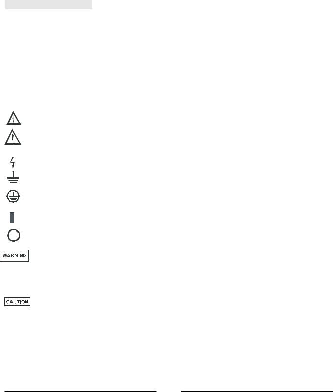
CAUTION Risk of Electrical Shock
Instruction manual symbol. The instrument will be marked with this symbol when it is necessary for the user to refer to the instruction manual.
Indicates hazardous voltage.
Indicates ground terminal.
Protective Ground Conductor Terminal
Off (Supply)
On (Supply)
The WARNING sign denotes a hazard. An attention to a procedure is called. Not following procedure correctly could result in personal injury.
A WARNING sign should not be skipped and all indicated conditions must be fully understood and met.
The CAUTION sign denotes a hazard. An attention to a procedure is called. Not following procedure correctly could result in damage to the equipment. Do not proceed beyond a CAUTION sign until all indicated conditions are fully understood and met.
FCC COMPLIANCE NOTICE:
Note: This equipment has been tested and found to comply with the limits for a Class A digital device, pursuant to part 15 of the FCC Rules. These limits are designed to provide reasonable protection against harmful interference when the equipment is operated in a commercial environment. This equipment generates electro-magnetic field, and can radiate radio frequency energy and, if not installed and used in accordance with the instruction manual, may cause harmful interference to radio communications. Operation of this equipment in a residential area is likely to cause harmful interference in which case the user will be required to correct the interference at his own expense.
3
83-507-5002 Rev. B

SICHERHEITS-INSTALLATIONS ANWEISUNGEN
Vorsicht
Vor Anschluss an das Netz ist die Aufstellanleitung wie nachstehend beschrieben zu beachten. Die nachstehenden Sicherheitsanweisugen mussen währendaller Phasen des Betriebes, des Services und der Reparatur dieser Ausrustung beachtet werden. Alle notwendigen Bedingungen die sicherstellen, dass die Einrichtung zu keiner Gefahr im Sinne dieser Norm führen kann, sind in diesem Handbuch beschrieben.
TDK-Lambda Americas Inc. ist nich verantwortlich fur Fehler, die bei der Inbetriebnahme des Gerates auf Grundlage dieser Sicherheitsanweisungen durch den Betreiber entstehen können.
Betriebsbedingungen
Die GenesysTM Stromversorgungs-Reihe ist zur installation gemass Uberspannungs-Kategorie 2 entwickelt worden.
Installatios Kategorie (Uberspannungs-Kategories) 2 bedeutet: Kleinindustrie, Geräte, bewegliche Ausrustung etc.. mit Uberspannungen kleiner als Installation Kategorie 3.
Erdungskonzept
Dieses Produkt ist ein Gerat mit Schutzklasse1. Damit gefahrliche Energieinhalte und Spannungen vermieden werden, ist das Geratechassis an eine Schutzerde anzuschliessen. Das Gerat muss an die AC-Wechselspannungsversorgung mit 3 Leitern (L, N, PE) angeschlossen werden. Der PEAnschluss ist an einen festen Erder anzuschliessen. Bei Festverdrahtung des Gerates ist sicherzustellen, dass der PE Anschluss als erstes durchgefuhrt wird.
Jede mogliche Unterbrechung des PE-Leiters oder Trennung der PE Masses kann einen moglichen elektrischen Schlag hervorrufen, der Personenschaden zur Folge hatte.
Vorsicht
Erdung des DC-Ausgangs
Es besteht Energiegefahr am RS232/RS485 und IEEE Anschluss, falls die Ausgangsspannung des Gerates grosser ist als 400V und der positive Ausgangsanschluss des Netzteiles geerdet wird. Dies gilt insbesondere auch bei Reihenschaltungen von unterschiedlichen Netzteilen. Wird die RS232/485 oder IEEE Schnittstelle verwendet, ist darauf zu achten, dass der Plus-Ausgangsanschluss nicht geerdet wird.
Absicherung
Sicherungen durfen nur durch autorisierte TDK-Lambda Americas Inc. Service Personen ausgetauscht werden. Um Brandgefahr vorzubeugen, sind nur Sicherungen zu verwenden mit gleicher Bauart und Auslosecharakteristik. Siehe hierzu Wartungsanweisungen in Kapitel 6 bezuglich Sicherungen.
Anschluss an Versorgungsstromkreis
Der Betrieb des Gerates ist nur fur den dafur spezifizierten Wechselspannungsbereich und der angegebenen Frequenz erlaubt.
Der Nominaleingangsspannungsbereich der GenesysTM Serie liegt bei 100-240VAC mit 50/60Hz. Fur einen sicheren Betrieb des Gerates ist eine Abweichung von max. +/-10% der Nominalspannung erlaubt.
Spannungsfuhrende Teile
Die Gerateabdeckung darf nur im stromlosen Zustand geoffnet werden. Interne Modifikationen, sowie Bauteileaustausch ist nur durch TDK-Lambda Americas Inc. qualifiziertes Personal erlaubt. Vor Austausch von Bauteilen ist das Netzkabel bzw. Die Versorgungsspannung zu trennen. Energieversorgungsanschlusse sind immer zu trennen um Personenverletzungen durch gefahrliche Energieinhalte und Spannungen auszuschliessen. Die Stromkreise sind zu entladen, extreme Spannunsquellen sind zu entfernen bevor Bauteile bzw. Komponenten getauscht werden.
4
83-507-5002 Rev. B
Anderungen and Bauteileersatz
Ersatzteilaustausch – und Anderungen durfen nur von autorisiertem TDK-Lambda Americas Inc. SERVICE-PERSONEN durchgefuhrt werden. Fur Reparaturen oder Anderungen ist das
Gerat zur TDK-Lambda Americas Inc. Service-Niederlassung zu retournieren.
SICHERHEITS-HINWEISE
Umweltbedingungen
Die GenesysTM Stromversorgungs-Serie ist gemassden Sicherheitsabnahmen fur folgende Betriebsbedingungen zugelassen.
*Stationare Einrichtungen in Gebauden. *Umgebungstemperaturebereich: 0-50°C.
*Maximale Relative Luftfeuchtigkeit: 90% (nicht kondensierend). *Betriebshohe: bis zu 3000m.
*Verschmutzungsgrad 2.
Sicherheits-und Warnsymbole
VORSICHT Spannungsfuhrende Teile-Gefahr durch elektrischen Schlag bzw. Energieinhalte
Handbuch-Symbol. Das Gerat bzw. Gerateteile werden mit diesem Symbol gekennzeichnet, wenn es fur den Benutzer notwendig ist, sich auf die Anweisungen im Handbuch zu beziehen.
Zeigt „spannungsfuhrende Teile“ mit gefahrlicher Spannung an.
Zeigt Masse-Anschluss an, keine Schutzerde. (z.B. Masseanschlussan einenVerbraucher).
Schutzleiter-Anschlussklemme.
Symbol fur Schalter oder Drucknopfe - Zeigt die "Ein" - Stellung hier an.
Symbol fur Schalter oder Drucknopfe - Zeigt die "Aus" - Stellung hier an.
Dieses Warnaufschrift weist auf eine Gefahr hin, die eine Uberprufunganweisung nach sich ziecht. Nichteinhaltung kann zu Personenschaden fuhren. Dieser Warnhinweis darf nicht ubersprungen werden und die beschriebene Vorgehensweise musstrikt verstanden werden und dementsprechend umgesetzt werden.
Diese „Vorsichtswarnung“ weist auf eine Gefahr hin, die einer Vorkehrung bedarf. Nichteinhaltung kann zur Zerstorung der Anlage oder des Gerates fuhren. Bitte berucksichtigen Sie alle Anweisungen, die dort beschreiben sind, bevor Sie mit Benutzung der Anlage bzw. des Gerates fortfahren.
5
83-507-5002 Rev. B

CHAPTER 1 GENERAL INFORMATION
1.1 USER MANUAL CONTENT
This User’s Manual contains the operating instructions, installation instructions and specifications of the GenesysTM GENH 750W power supply series. The instructions refer to the standard power supplies, including the built-in RS232/RS485 serial communication. For information related to operation with the optional IEEE programming, refer to User’s Manual for Power Supply IEEE Programming Interface. (TDK-Lambda Americas Inc. P/N 83-030-200).
1.2 INTRODUCTION
1.2.1General Description
GenesysTM power supplies are wide output range, high performance switching power supplies. The GenesysTM series is power factor corrected and operates from worldwide AC voltage range continuously. Output Voltage and Current are continuously displayed and LED indicators show the complete operating status of the power supply. The Front panel controls allow the user to set the output parameters, the protections levels (Over-Voltage protection, Under-Voltage limit and Foldback) and preview the settings. The rear panel includes the necessary connectors to control and monitor the power supply operation by remote analog signals or by the built-in serial communication (RS232/RS485). GPIB programming and Isolated-Analog programming/monitoring are optional.
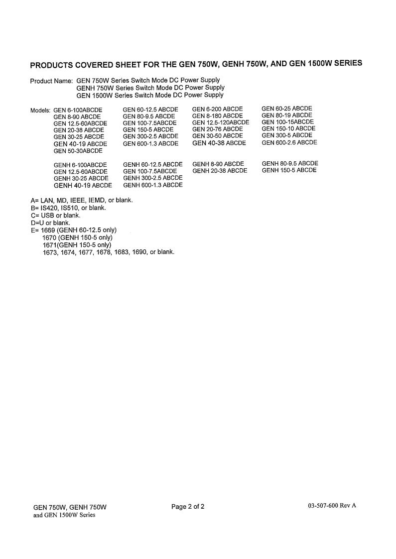
1.2.2Models covered by this Manual
Model |
|
Voltage |
Current |
Model |
|
|
Voltage |
Current |
||||
|
|
range (V) |
range (A) |
|
|
|
range (V) |
range (A) |
||||
GENH 6 |
- 100 |
0 |
- 6 |
0 |
- 100 |
GENH 60 |
- 12.5 |
0 |
- 60 |
0 |
- 12.5 |
|
GENH 8 |
- 90 |
0 |
- 8 |
0 |
- 90 |
GENH 80 |
- 9.5 |
0 |
- 80 |
0 |
- 9.5 |
|
GENH 12.5 - 60 |
0 |
- 12.5 |
0 |
- 60 |
GENH 100 - 7.5 |
0 |
- 100 |
0 |
- 7.5 |
|||
GENH 20 - 38 |
0 |
- 20 |
0 |
- 38 |
GENH 150 |
- 5 |
0 |
- 150 |
0 |
- 5 |
||
GENH 30 - 25 |
0 |
- 30 |
0 |
- 25 |
GENH 300 |
- 2.5 |
0 |
- 300 |
0 |
- 2.5 |
||
GENH 40 - 19 |
0 |
- 40 |
0 |
- 19 |
GENH 600 |
- 1.3 |
0 |
- 600 |
0 |
- 1.3 |
||
|
|
|
|
Table 1-1: Models covered by the Manual |
|
|
|
|
||||
1.2.3Features and options
Constant Voltage / Constant Current with automatic crossover.
Active power factor correction.
Universal Input Voltage (85i265Vac), continuous operation.
Embedded Microprocessor Controller.
Built-in RS-232/RS-485 Interface.
Voltage & Current high resolution adjustment by digital encoders.
High accuracy programming/readback.
Software Calibration (no internal trimmers / potentiometers).
Last Setting Memory.
Independent Remote ON/OFF (opto-isolated) and remote Enable/Disable.
6
83-507-5002 Rev. B
Parallel operation (Master/Slave) with Active current sharing.
Remote sensing to compensate for voltage drop of power leads.
External Analog Programming and Monitoring standard (0-5V or 0-10V, user selectable).
Cooling fan speed control for low noise and extended fan life.
Zero stacking-no ventilation holes at the top and bottom surface of the power supply.
Optional GPIB interface (SCPI compatible).
Optional Isolated Analog programming/monitoring (0-5V or 0-10V, user selectable and 4- 20mA).
1.2.4Multiple output power system
The GenesysTM power supplies series can be configured into a programmable power system of up to 31 units using the built-in RS232/RS485 communication port and the RS485 linking cable provided with each power supply.
In a GPIB system, each power supply can be controlled using the optional GPIB controller (factory installed).
1.2.5Control via the serial communication port
The following parameters can be programmed / monitored via the serial communication port:
1.Output Voltage setting.
2.Output Current setting.
3.Output Voltage measurement.
4.Output On/Off control.
5.Output Current measurement.
6.Foldback protection setting
7.Over-voltage protection setting and readback.
8.Under-Voltage limit setting and readback.
9.Power-supply start up mode (Auto-restart or Safe-start mode).
1.2.6Analog voltage programming and monitoring
Analog inputs and outputs are provided at the rear panel for analog control of the power supply. The Output Voltage and the Current can be programmed by analog voltage or by resistor, and can be monitored by analog voltage. The power supply output can be remotely set to On or Off and analog signals monitor the proper operation of the power supply and the mode of operation (CV/CC).
1.2.7Parallel operation
GenesysTM power supplies of the same Output Voltage and Current rating can be paralleled in a master-slave configuration with automatic current sharing to increase power available.
1.2.8Output connections
Output connections are made to rear panel bus-bars for models up to 60V and to a 4-terminal wire clamp connector for models above 60V rated output voltage. Either the positive or negative terminal may be grounded or the output may be floated. Models up to 60VDC Rated Output shall not float outputs more than +/- 60VDC above/below chassis ground. Models >60VDC Rated Output shall not float outputs more than +/-600VDC above/below chassis ground. Contact factory for assistance with higher float voltage applications.
Local or remote sense may be used. In remote sense, the voltage drop on the load wires should be minimized. Refer to the specifications for the maximum voltage drop value.
7
83-507-5002 Rev. B

1.2.9Cooling and mechanical construction
The GenesysTM series is cooled by internal fans. At the installation, care must be taken to allow free airflow into the power supply via the front panel and out of the power supply via the rear panel. The GenesysTM power supplies have a compact and lightweight package, which allows easy installation and space saving in the application equipment.
CAUTION
Observe all torque guidelines within this manual. Applying more torque may damage unit or accessories. Such damage is not covered under manufacturers warranty.
1.3 ACCESSORIES
1.3.1 Included Accessories
The following accessories are delivered with the power supply:
1.3.1.1 Serial Link Cable
Serial link cable for linking power supplies by RS-485 communication.GEN/RJ45.
Cable description: 0.5m Length, shielded, RJ-45 type plugs, eight (8) contacts (P/N 15-507-201)
1.3.1.2 Hardware (delivered with power supply)
•Strain Relief for AC Cord
•Output terminal Shield
•DB25 Programming Plug kit (AMP 749809-9)
•Plastic legs for bench mounting.
•Power Cord - See Para 1.3.3.
1.3.2 Optional Communication Cables (See Para. 7.5)
•RS-232 Cables to connect GEN to Serial Port on PC
GEN to PC (DB9) |
GEN 232/9 |
P/N 15-507-203 |
GEN to PC (DB25) |
GEN 232/25 |
P/N 15-507-204 |
•RS-485 Cable to connect GEN to Serial Port on PC
GEN to PC (DB9) |
GEN/485-9 |
P/N 15-507-202) |
1.3.3AC cables
AC Cables are provided with 750W Model only, according to suffix in Model Number.
Part No. |
Market |
Description |
NC301 |
USA |
13A 125V, unshielded, 2m typical length, with IEC320 connector on one end |
(GEN/U) |
|
and NEMA-5-15P connector on the other end. |
NC302 |
Europe |
10A 250V, unshielded, 2m typical length, with IEC320 connector on one end |
(GEN/E) |
|
and INT’L 7 standard VII, dual earthing. |
NC303 |
General |
10A 250V, unshielded, 2m typical length, with IEC320 connector on one end |
(GEN/O) |
|
and unterminated stripped wires on the other end. Use the cable only with |
|
|
plug approved by the national safety standards of the country of usage. |
NC305 |
Japan |
13A 125V,unshielded, 2m typical length, with IEC320 connector on one end |
(GEN/J) |
|
and Japan type plug on the other end. |
NC306 |
UK |
10A 250V unshielded, 2m typical length, with IEC320 connector on one end |
(GEN/GB) |
|
and UK type plug on the other end. |
8
83-507-5002 Rev. B

CHAPTER 2 |
SPECIFICATIONS |
|
|
|
|
|
|
|
|
|
|
|
|
|
|
|
|
|
|
|||||
|
2.1 OUTPUT RATING |
|
|
|
|
|
|
|
|
|
|
|
|
|
|
|
|
|
|
|
|
|
|
|
|
MODEL |
|
GEN |
6-100 |
|
8-90 |
12.5-60 |
|
20-38 |
|
30-25 |
40-19 |
|
– |
|
60-12.5 |
80-9.5 |
|
100-7.5 |
|
150-5 |
300-2.5 |
600-1.3 |
|
|
1.Rated output voltage (*1) |
|
V |
6 |
|
8 |
12.5 |
|
20 |
|
30 |
40 |
|
– |
|
60 |
80 |
|
100 |
|
150 |
300 |
600 |
|
|
2.Rated output current 750W (*2) |
|
A |
100 |
|
90 |
60 |
|
38 |
|
25 |
19 |
|
– |
|
12.5 |
8.5 |
|
7.5 |
|
5 |
2.5 |
1.3 |
|
|
3.Rated output power 750W |
|
W |
600 |
|
720 |
750 |
|
760 |
|
750 |
760 |
|
– |
|
750 |
760 |
|
750 |
|
750 |
750 |
780 |
|
|
|
|
|
|
|
|
|
|
|
|
|
|
|
|
|
|
|
|
|
|
|
|||
|
MODEL |
|
GEN |
6-200 |
|
8-180 |
12.5-120 |
|
20-76 |
|
30-50 |
40-38 |
|
50-30 |
|
60-25 |
80-19 |
|
100-15 |
|
150-10 |
300-5 |
600-2.6 |
|
|
1.Rated output voltage (*1) |
|
V |
6 |
|
8 |
12.5 |
|
20 |
|
30 |
40 |
|
50 |
|
60 |
80 |
|
100 |
|
150 |
300 |
600 |
|
|
2.Rated Output Current 1500W (*2) |
|
A |
200 |
|
180 |
120 |
|
76 |
|
50 |
38 |
|
30 |
|
25 |
19 |
|
15 |
|
10 |
5 |
2.6 |
|
|
3.Rated output power 1500W |
|
W |
1200 |
|
1440 |
1500 |
|
1520 |
|
1500 |
1520 |
|
1500 |
|
1500 |
1520 |
|
1500 |
|
1500 |
1500 |
1560 |
|
|
2.2 INPUT CHARACTERISTICS |
|
|
|
|
|
|
|
|
|
|
|
|
|
|
|
|
|
|
|
|
|
||
|
|
V |
6 |
|
8 |
12.5 |
|
20 |
|
30 |
40 |
|
50 |
|
60 |
80 |
|
100 |
|
150 |
300 |
600 |
||
|
1. |
Input voltage/freq. (*3) |
|
– |
85~265Vac |
continuous, |
47-63Hz, single phase. |
|
|
|
|
|
|
|
|
|
|
|
|
|
||||
|
2. |
Input current (at 100/200Vac) |
|
A |
10.5/5 for 750W model, 21/11 for 1500W models. |
|
|
|
|
|
|
|
|
|
|
|
|
|
||||||
|
3. |
Power Factor |
|
– |
0.99@100/200Vac, rated output power. |
|
|
|
|
|
|
|
|
|
|
|
|
|
||||||
|
4. |
750W models Efficiency (*4) |
|
% |
76/78 |
|
77/80 |
81/84 |
|
82/85 |
|
82/85 |
83/87 |
|
83/87 |
|
83/87 |
83/87 |
|
83/87 |
|
83/87 |
83/87 |
83/87 |
|
5. |
1500W models Efficiency (*4) |
|
% |
77/79 |
|
78/81 |
82/85 |
|
83/86 |
|
83/86 |
84/88 |
|
84/88 |
|
84/88 |
84/88 |
|
84/88 |
|
84/88 |
84/88 |
84/88 |
|
6. |
Inrush current at 100/200V |
|
A |
Less than |
25A for 750W models, 50A for 1500W models. |
|
|
|
|
|
|
|
|
|
|
|
|
||||||
|
2.3 CONSTANT VOLTAGE MODE |
|
|
|
|
|
|
|
|
|
|
|
|
|
|
|
|
|
|
|
|
|
||
|
|
V |
6 |
|
8 |
12.5 |
|
20 |
|
30 |
40 |
|
50 |
|
60 |
80 |
|
100 |
|
150 |
300 |
600 |
||
|
1. |
Max.Line regulation (*5) |
|
– |
0.01% of |
rated output |
voltage +2mV |
|
|
|
|
|
|
|
|
|
|
|
|
|
|
|
|
|
|
2. |
Max.Load regulation (*6) |
|
– |
0.01% of rated output voltage +2mV |
|
|
|
|
|
|
|
|
|
|
|
|
|
|
|
||||
|
3. |
Ripple and noise (p-p,20MHz) (*10) |
mV |
60 |
|
60 |
60 |
|
60 |
|
60 |
60 |
|
60 |
|
60 |
80 |
|
80 |
|
100 |
150 |
300 |
|
|
4. |
Ripple r.m.s., 5Hz~1MHz (*10) |
|
mV |
8 |
|
8 |
8 |
|
8 |
|
8 |
8 |
|
8 |
|
8 |
8 |
|
8 |
|
10 |
25 |
60 |
|
5. |
Temperature coefficient |
|
PPM/°C |
100PPM/°C |
of rated output voltage, following 30 min utes warm up |
|
|
|
|
|
|
|
|
|
|
|
|||||||
|
6. |
Temperature drift |
|
– |
0.05% of rated Vout over 8hrs interval following 30 minutes warm-up. Constant line, load & temp. |
|
|
|
|
|
||||||||||||||
|
7. |
Rem. Sense compensation/wire |
|
V |
1 |
|
1 |
1 |
|
1 |
|
1.5 |
2 |
|
2 |
|
3 |
4 |
|
5 |
|
5 |
5 |
5 |
|
8. |
Up-prog. Response time 0~Vomax (*9) |
mS |
|
|
|
|
|
80 |
|
|
|
|
|
|
|
|
|
150 |
|
|
250 |
||
|
9. |
Down-prog. Response time: Full load |
mS |
10 |
|
|
50 |
|
|
|
|
|
80 |
|
|
|
|
150 |
|
|
250 |
|||
|
|
|
No load |
|
500 |
|
600 |
700 |
|
800 |
|
900 |
1000 |
|
1100 |
|
1100 |
1200 |
|
1500 |
|
2000 |
2500 |
4000 |
|
10. Transient response time |
|
mS |
Time for the output voltage to recover within 0.5% of its rated output for a load change 10~90% of rated |
|
|
|
|
|
|||||||||||||||
|
|
|
|
|
output current. |
|
|
|
|
|
|
|
|
|
|
|
|
|
|
|
|
|
||
|
|
|
|
|
Output set-point: 10~100%. |
|
|
|
|
|
|
|
|
|
|
|
|
|
|
|
||||
|
|
|
|
|
Less than 1mS for models up to and including 100V; 2mS for models above 100V. |
|
|
|
|
|
|
|
||||||||||||
|
11. Hold-up time |
|
mS |
More than 20mS, 100Vac, rated output power. |
|
|
|
|
|
|
|
|
|
|
|
|
|
|||||||
|
2.4 CONSTANT CURRENT MODE |
|
|
|
|
|
|
|
|
|
|
|
|
|
|
|
|
|
|
|
|
|
||
|
|
V |
6 |
|
8 |
12.5 |
|
20 |
|
30 |
40 |
|
50 |
|
60 |
80 |
|
100 |
|
150 |
300 |
600 |
||
|
1. |
Max.line regulation (*5) |
|
– |
0.01% of |
rated output |
voltage +2mA |
|
|
|
|
|
|
|
|
|
|
|
|
|
|
|
|
|
|
2. |
Max.load regulation (*7) |
|
– |
0.02% of rated output current +5mA |
|
|
|
|
|
|
|
|
|
|
|
|
|
|
|
||||
|
3. |
Ripple r.m.s. 5Hz~1MHz.750W (*8) |
mA |
200 |
|
180 |
120 |
|
76 |
|
63 |
48 |
|
– |
|
38 |
29 |
|
23 |
|
18 |
13 |
8 |
|
|
|
1500W (*8) |
mA |
400 |
|
360 |
240 |
|
152 |
|
125 |
95 |
|
75 |
|
75 |
57 |
|
45 |
|
35 |
25 |
12 |
|
|
4. |
Temperature coefficient |
|
PPM/°C |
100PPM/°C |
from rated |
output current, |
following |
30 m inutes |
warm-up. |
|
|
|
|
|
|
|
|
|
|
||||
|
5. |
Temperature drift |
|
– |
0.05% of rated lout over 8hrs interval following 30 minutes warm-up. Constant line, load & temp. |
|
|
|
|
|
||||||||||||||
|
2.5 ANALOG PROGRAMMING AND MONITORING |
|
|
|
|
|
|
|
|
|
|
|
|
|
|
|
|
|
|
|
|
|
||
|
1.Vout voltage programming |
|
– |
0~100%, 0~5V or 0~10V, user select. Accuracy and linearity; +/-0.5% of rated Vout. |
|
|
|
|
|
|
|
|||||||||||||
|
2. |
Iout voltage programming |
|
– |
0~100%, 0~5V or 0~10V, user select. Accuracy and linearity; +/-1% of rated Iout. |
|
|
|
|
|
|
|
|
|||||||||||
|
3. |
Vout resistor progrmming |
|
– |
0~100%, 0~5/10Kohm full scale, user select. Accuracy and linearity: +/-1% of rated Vout. |
|
|
|
|
|
|
|
||||||||||||
|
4. |
Iout resistor programming |
|
– |
0~100%, 0~5/10Kohm full scale, user select. Accuracy and linearity: +/-1.5% of rated Iout. |
|
|
|
|
|
|
|
||||||||||||
|
5. |
On/off control |
|
– |
By electrical Voltage: 0~0.6V/2~15V or dry contact, user selectable logic. |
|
|
|
|
|
|
|
|
|||||||||||
|
6. |
Output current monitor |
|
– |
0~5V or 0~10V, user selectable. Accuracy: 1% |
|
|
|
|
|
|
|
|
|
|
|
|
|
||||||
|
7. |
Output voltage monitor |
|
– |
0~5V or 0~10V, user selectable. Accuracy: 1% |
|
|
|
|
|
|
|
|
|
|
|
|
|
||||||
|
8. |
Power supply OK signal |
|
– |
4~5V-OK, 0V-Fail, 500ohm series resistance. |
|
|
|
|
|
|
|
|
|
|
|
|
|
||||||
|
9. |
Parallel operation |
|
– |
Possible, up to 4 units in master/slave mode with single wire current balance connection. |
|
|
|
|
|
|
|
||||||||||||
|
10. Series operation |
|
– |
Possible (with external diodes), up to 2 units. |
|
|
|
|
|
|
|
|
|
|
|
|
|
|||||||
|
11. CV/CC inicator |
|
– |
CV: TTL high (4~5V), source current: 10mA, CC: TTL low (0-0.6V). Sink current: 10mA . |
|
|
|
|
|
|
|
|||||||||||||
|
12. Enable/Disable |
|
– |
Dry contact. Open: off, Short: on. Max. voltage at Enable/Disable in: 6V. |
|
|
|
|
|
|
|
|
||||||||||||
|
13. Local/Remote analog control |
|
– |
By electrical signal or Open/Short: 0~0.6V or short: Remote, 4~5V or open: Local. |
|
|
|
|
|
|
|
|
||||||||||||
|
14. Local/remote analog indicator |
|
– |
Open collector. Local: Open, Remote: On. Maximum voltage: 30V, maximum sink current: 5mA. |
|
|
|
|
|
|||||||||||||||
9
83-507-5002 Rev. B
2.6 PROGRAMMING AND READBACK (RS232/485, Optional IEEE Interface)
1. |
Vout programming accuracy |
|
– |
|
0.05% + 0.05% of rated output voltage. |
|
|
|
|
|
|
|
|
|
|
|
|
|
|||
2. |
Iout programming accuracy (*13) |
|
– |
|
0.1% of actual output current + 0.1% of rated output current (for Iout >0.4% of rated Iout to 100% of rated Iout). |
|
|
|
|||||||||||||
|
|
|
|
|
0.1% of actual output current +0.4% of rated output current (for Iout <0.4% of rated Iout to 0.4% of rated Iout). |
|
|
|
|||||||||||||
3. |
Vout programming resolution. |
|
– |
|
0.012% of full scale. |
|
|
|
|
|
|
|
|
|
|
|
|
|
|
|
|
4. |
Iout programming resolution |
|
– |
|
0.012% of full scale. |
|
|
|
|
|
|
|
|
|
|
|
|
|
|
|
|
5. |
Vout readback accuracy |
|
– |
|
0.1% + 0.1% of rated output voltage |
|
|
|
|
|
|
|
|
|
|
|
|
|
|||
6. |
Iout readback accuracy (*13) |
|
– |
|
0.1% + 0.3% of rated output current |
|
|
|
|
|
|
|
|
|
|
|
|
|
|||
7. |
Vout readback resolution |
|
– |
|
0.012% of full scale |
|
|
|
|
|
|
|
|
|
|
|
|
|
|
|
|
8. |
Iout readback resolution |
|
– |
|
0.012% of full scale |
|
|
|
|
|
|
|
|
|
|
|
|
|
|
|
|
2.7 PROTECTIVE FUNCTIONS |
|
|
|
|
|
|
|
|
|
|
|
|
|
|
|
|
|
|
|
||
|
V |
|
6 |
8 |
12.5 |
|
20 |
|
30 |
40 |
50 |
60 |
|
80 |
|
100 |
150 |
300 |
600 |
||
1. |
Foldback protection |
|
Output shut |
-down when power supply changes from CV to CC. User presetable. |
|
|
|
|
|
|
|
|
|
||||||||
2. |
Over-voltage protection |
|
Inverter shut-down; manual reset by AC input recycle, OUT button. |
|
|
|
|
|
|
|
|
|
|
||||||||
3. |
Over-voltage trip point |
|
V |
|
0.5-7.5 |
0.5-10 |
1-15 |
|
1-24 |
|
2-35 |
2-44.1 |
5-57 |
5-66 |
|
5-88 |
|
5-110 |
5-165 |
5-330 |
5-660 |
4. |
Output under voltage limit |
|
Preset by |
front panel |
or communication port. Prevents adjusting Vout below limit. Raises the PS_OK signal in case |
|
|
|
|
||||||||||||
|
|
|
output |
voltage is below limit. |
|
|
|
|
|
|
|
|
|
|
|
|
|
|
|
||
5. |
Over temperature protection |
|
User selectable, latched or non latched. |
|
|
|
|
|
|
|
|
|
|
|
|
|
|||||
2.8 FRONT PANEL |
|
|
|
|
|
|
|
|
|
|
|
|
|
|
|
|
|
|
|
|
|
1. |
Control functions |
|
– |
|
Vout/Iout manual adjust by separate encoders. (Coarse and fine adjustment) |
|
|
|
|
|
|
|
|
||||||||
|
|
|
– |
|
OVP/UVL manual adjust by Volt. Adjust encoder |
|
|
|
|
|
|
|
|
|
|
|
|||||
|
|
|
– |
|
Address selection by Voltage adjust encoder. No of addresses: 31 |
|
|
|
|
|
|
|
|
|
|||||||
|
|
|
– |
|
Go to local control |
|
|
|
|
|
|
|
|
|
|
|
|
|
|
|
|
|
|
|
– |
|
Output on/off |
|
|
|
|
|
|
|
|
|
|
|
|
|
|
|
|
|
|
|
– |
|
AC on/off |
|
|
|
|
|
|
|
|
|
|
|
|
|
|
|
|
|
|
|
– |
|
Front panel lock |
|
|
|
|
|
|
|
|
|
|
|
|
|
|
|
|
|
|
|
– |
|
Foldback control |
|
|
|
|
|
|
|
|
|
|
|
|
|
|
|
|
|
|
|
– |
|
Serial or IEEE display at power-up |
|
|
|
|
|
|
|
|
|
|
|
|
|
|||
|
|
|
– |
|
Baud rate selection: 1200, 2400, 4800, 9600 and 19200 |
|
|
|
|
|
|
|
|
|
|
||||||
|
|
|
– |
|
Re-start modes (Auto Restart, Safe Start) |
|
|
|
|
|
|
|
|
|
|
|
|||||
2. |
Display |
|
– |
|
Vout: |
4 digits, accuracy: 0.5% of rated voltage + 1 count |
|
|
|
|
|
|
|
|
|
||||||
|
|
|
– |
|
Iout: |
4 digits, accuracy: 0.5% of rated current + 1 count |
|
|
|
|
|
|
|
|
|
||||||
3. Indications |
|
– |
|
VOLTAGE, |
CURRENT, ALARM FINE, PREVIEW, FOLDBACK, LOCAL, OUTPUT ON. |
|
|
|
|
|
|
||||||||||
2.9 ENVIRONMENTAL CONDITIONS |
|
|
|
|
|
|
|
|
|
|
|
|
|
|
|
|
|
|
|
|
|
1. |
Operating temperature |
|
C |
|
0~50 C, 100% load. |
|
|
|
|
|
|
|
|
|
|
|
|
|
|
|
|
2. |
Storage temperature |
|
C |
|
-20 to + 70 |
|
|
|
|
|
|
|
|
|
|
|
|
|
|
|
|
3. |
Operating humidity |
|
% |
|
30~90% RH (no condensation). |
|
|
|
|
|
|
|
|
|
|
|
|
|
|||
4. |
Storage humidity |
|
% |
|
10~95% RH (no condensation). |
|
|
|
|
|
|
|
|
|
|
|
|
|
|||
5. |
Altitude |
|
– |
|
Maximum 3000m, Derate output current by 2%/100m above 2000m. Alternatively, derate maximum ambient |
|
|
|
|||||||||||||
|
|
|
|
|
temperature by 1 degC/100m above 2000m. |
|
|
|
|
|
|
|
|
|
|
|
|||||
2.10 MECHANICAL |
|
|
|
|
|
|
|
|
|
|
|
|
|
|
|
|
|
|
|
|
|
1. |
Cooling |
|
– |
|
Forced air cooled by internal fans. |
|
|
|
|
|
|
|
|
|
|
|
|
|
|||
2. |
Weight |
|
Kg |
|
Less than 4.5Kg |
|
|
|
|
|
|
|
|
|
|
|
|
|
|
|
|
3. |
Dimensions (W x H x D) |
|
mm |
|
W: 214.0 H: 43.6 (57.0 Benchtop Version). D: 437.5 (Refer to Outline drawing). |
|
|
|
|
|
|
|
|
||||||||
4. |
Vibration |
|
– |
|
MIL-810E, method 514.5 test condition l-3.3 |
|
|
|
|
|
|
|
|
|
|
|
|||||
5. |
Shock |
|
– |
|
Less than 20G, half sine, 11mS. Units unpacked |
|
|
|
|
|
|
|
|
|
|
|
|||||
2.11 SAFETY/EMC |
|
|
|
|
|
|
|
|
|
|
|
|
|
|
|
|
|
|
|
|
|
1. |
Applicable standards |
Safety |
– |
|
UL60950-1 listed, EN60950-1 Vout ≤ 40V: Output is SELV, IEEE/Isolated Analog are SELV. |
|
|
|
|
|
|
||||||||||
|
|
|
|
|
|
|
60 < Vout < 400V: Output is hazardous, IEEE/Isolated analog are SELV |
|
|
|
|
||||||||||
|
|
|
|
|
|
|
400 < Vout < 600V: Output is hazardous, IEEE/Isolated, Analog are not SELV |
|
|
|
|||||||||||
|
|
EMC |
– |
|
EN55024 |
|
|
|
|
|
|
|
|
|
|
|
|
|
|
|
|
2. |
Withstand voltage |
|
– |
|
Vout < 60V models: Input-Outputs (SELV): 3.0KVrms 1 min, Input-Ground: 2.0KVrms 1 min. |
|
|
|
|
|
|
||||||||||
|
|
|
|
|
60 ≤ Vout ≤ 600V models: Input-Haz, output: 2.5KVrms 1 min, Input-SELV: 3KVrms 1 min, 1900VDC 1 min. |
|
|
|
|||||||||||||
|
|
|
|
|
Hazardous Output - SELV: 1.9KVrms 1 min, Hazardous Output-Ground: 1.9KVrms 1 min. |
|
|
|
|
|
|
||||||||||
|
|
|
|
|
Input-Ground: 2KVrms 1min |
|
|
|
|
|
|
|
|
|
|
|
|
|
|||
3. |
Insulation resistance |
|
– |
|
More than 100Mohm at 25°C, 70%RH |
|
|
|
|
|
|
|
|
|
|
|
|
|
|||
4. |
Conducted emission |
|
– |
|
EN55022B, FCC part 15-B, VCCI-B |
|
|
|
|
|
|
|
|
|
|
|
|
|
|||
5. |
Radiated emission |
|
– |
|
EN55022A, FCC part 15-A, VCCI-A |
|
|
|
|
|
|
|
|
|
|
|
|
|
|||
10
83-507-5002 Rev. B
NOTES:
*1: Minimum voltage is guaranteed to maximum 0.2% of the rated output voltage. *2: Minimum current is guaranteed to maximum 0.4% of the rated output current.
*3: For cases where conformance to various safety standards (UL, IEC etc.) is required, to be described as 100-240Vac (50/60Hz).
*4: At 100/200V input voltage and maximum output power. *5: From 85i132Vac or 170i265Vac, constant load.
*6: From No-load to Full-load, constant input voltage. Measured at the sensing point in Remote Sense.
*7: For load voltage change, equal to the unit voltage rating, constant input voltage.
*8: For 6V models the ripple is measured at 2i6V output voltage and full output current. For other models, the ripple is measured at 10i100% output voltage and full output current.
*9: With rated, resistive load.
*10. For 6i300V models: Measured with JEITA RC-9131A (1:1) probe For 600V model: Measured with (10:1) probe.
2.12 SUPPLEMENTAL CHARACTERISTICS
The supplemental characteristics give typical but non-warranted performance characteristics. The supplemental characteristics are useful in assessing applications for the power supply. Several kinds of supplemental characteristics are listed below.
1.Evaluation Data: Typical performance of the power supply.
2.Reliability Data: Reliability Performance of the power supply.
3.IEC1000 Data: Performance of the power supply under IEC1000 test conditions.
4.EMI Data: Typical EMI (conducted and radiated) performance of the power supply.
The supplemental characteristics data is held in each TDK-Lambda Americas Inc. sales and service facility. For further details please contact the TDK-Lambda Americas Inc. office nearest you.
11
83-507-5002 Rev. B
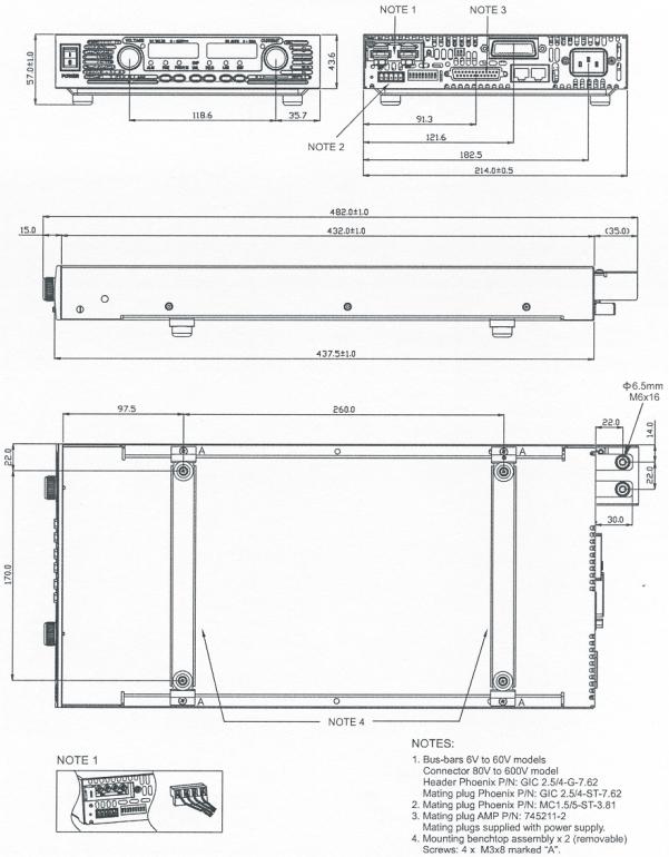
2.13 GENESYSTM GENH 750W POWER SUPPLIES OUTLINE DRAWINGS
12
83-507-5002 Rev. B
CHAPTER 3 INSTALLATION
3.1 GENERAL
This Chapter contains instructions for initial inspection, preparation for use and repackaging for shipment. Connection to PC, setting the communication port and linking GenesysTM power supplies are described in Chapter 7.
NOTE
GenesysTM power supplies generate magnetic fields, which might affect the operation of other instruments. If your equipment is susceptible to magnetic fields, do not position it adjacent to the power supply.
3.2 PREPARATION FOR USE
In order to be operational, the power supply must be connected to an appropriate AC source. The AC source voltage should be within the power supply specification. Do not apply power before reading Section 3.6 and 3.7.
Table 3-1 below, describes the basic setup procedure. Follow the instructions in Table 3-1 in the sequence given to prepare the power supply for use.
Step no. |
Item |
Description |
Reference |
|
|
|
|
1 |
Inspection |
Initial physical inspection of the power supply |
Section 3.3 |
|
|
|
|
2 |
Installation |
Installing the power supply, |
Section 3.4 |
|
|
Ensuring adequate ventilation. |
Section 3.5 |
|
|
|
|
3 |
AC source |
AC source requirements |
Section 3.6 |
|
|
Connecting the power supply to the AC source |
Section 3.7 |
|
|
|
|
4 |
Test |
Turn-on checkout procedure. |
Section 3.8 |
|
|
|
|
5 |
Load connection |
Wire size selection. Local/Remote sensing. |
Section 3.9 |
|
|
Single or multiple loads. |
|
|
|
|
|
6 |
Default setting |
The power supply setting at shipment. |
Section 7.2.1 |
|
|
|
|
Table 3-1: Basic setup procedure
3.3 INITIAL INSPECTIONS
Prior to shipment this power supply was inspected and found free of mechanical or electrical defects. Upon unpacking of the power supply, inspect for any damage, which may have occurred in transit.
The inspection should confirm that there is no exterior damage to the power supply such as broken knobs or connectors and that the front panel and meters face are not scratched or cracked. Keep all packing material until the inspection has been completed. If damage is detected, file a claim with carrier immediately and notify the TDK-Lambda Americas Inc. sales or authorized service facility nearest you.
13
83-507-5002 Rev. B
3.4 RACK MOUNTING
To install a GENH750W one unit or two units side-by-side in a standard 19” Rack in 1U (1.75”) height, use option kit P/N: GENH/RM
The Rack Mount kit allows the units to be zero stacked for maximum system flexibility and power density without increasing the 1U height of the units.
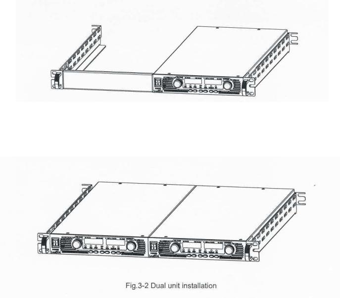
3.4.1 Single unit installation
To install a GENH750W power supply in a standard 19” Rack in 1U (1.75”) height, using a GENH Rack Mount kit P/N: GENH/RM.
Fig. 3-1 Single unit installation
3.4.2 Dual unit installation
To install two GENH750W power supplies side-by-side in a standard 19” Rack in 1U (1.75”) height, using a GENH Rack Mount kit P/N: GENH/RM.
14
83-507-5002 Rev. B
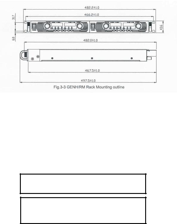
3.4.3 GENH/RM Rack Mounting outline drawings:
3.5 LOCATION, MOUNTING AND COOLING
This power supply is fan cooled. The air intake is at the front panel and the exhaust is at the rear panel. Upon installation allow cooling air to each the front panel ventilation inlets. Allow minimum 10cm (4-inch) of unrestricted air space at the front and the rear of the unit.
The power supply should be used in an area that the ambient temperature does not exceed +50°C.
3.6 AC SOURCE REQUIREMENTS
The GenesysTM series can be operated from a nominal 100V to 240V, single phase, 47i63 Hz. The input voltage range and current required for each model is specified in Chapter 2. Ensure that under heavy load, the AC voltage supplied to the power supply does not fall below the specifications described in Chapter 2.
3.7 AC INPUT POWER CONNECTION
CAUTION
Connection of this power supply to an AC power source should be made by an electrician or other qualified personnel
WARNING
There is a potential shock hazard if the power supply chassis (with cover in place) is not connected to an electrical safety ground via the safety ground in the AC input connector.
15
83-507-5002 Rev. B

WARNING
Some components inside the power supply area are at AC voltage even when the On/Off switch is in the “Off” position. To avoid electric shock hazard, disconnect the line cord and load and wait two minutes before removing cover.
3.7.1 AC Input Connector
An IEC connector is provided on the rear panel for connecting the unit to the AC power source with an AC cord. The IEC connector also provides the safety ground connection while the AC cord is plugged into an appropriate AC receptacle.
3.7.2 AC Input Cord
Refer to Section 1.3.4 for details of the AC input cords recommended for the GENH750W models.
WARNING
The AC input cord is the disconnect device of the power supply. The plug must be readily identifiable and accessible to the user. The AC input cord must be no longer than 3m.
3.8 TURN-ON CHECKOUT PROCEDURE
3.8.1 General
The following procedure ensures that the power supply is operational and may be used as a basic incoming inspection check. Refer to Fig.4-1 and Fig.4-2 for the location of the controls indicated in the procedure.
3.8.2 Prior to Operation
1.Ensure that the power supply is configured to the default setting:
–AC On/Off switch at Off position.
–Dip switch: All positions at Down (“Off”) position.
–Sense connector: Configured to Local Sense as shown in Fig.3-4:
1 Remote (+) sense
2 Local (+) sense
3 Not connected
4 Local (-) sense
5 Remote (-) sense
Fig.3-4: Sense connector default connection
–For units equipped with IEEE option, ensure that the IEEE_En switch is in Up (default) position (Refer to Fig.4-2, Item 9 for location), if checkout is to be done in IEEE mode.
2.Connect the unit to an AC source as described in Section 3.7.
3.Connect a DVM with appropriate cables for the rated voltage to the output terminals.
4.Turn the front panel AC power switch to On.
16
83-507-5002 Rev. B
3.8.3Constant Voltage Check
1.Turn on the output by pressing the OUT pushbutton so the OUT LED illuminates.
2.Observe the power supply VOLT display and rotate the Voltage encoder. Ensure that the Output Voltage varies while the VOLT encoder is rotated. The minimum control range is from zero to the maximum rated output for the power supply model.
Compare the DVM reading with the front panel VOLT display to verify the accuracy of the VOLT display. Ensure that the front panel VOLT LED is On.
3.Turn Off the front panel AC power switch.
3.8.4Constant Current Check
1.Ensure that the front panel AC power switch is at the Off position and the DVM connected to the output terminals shows zero voltage.
2.Connect a DC shunt across the output terminals. Ensure that the shunt and the wire current ratings are higher than the power supply rating. Connect a DVM to the shunt.
3.Turn the front panel AC power switch to the On position,
4.Turn On the output by pressing OUT pushbutton so the OUT LED illuminates.
5.Observe the power supply CURRENT display and rotate the CURRENT encoder. Ensure that the Output Current varies while the CURRENT encoder is rotated. The minimum control range is from zero to the maximum rated output for the power supply model.
Compare the DVM reading with the front panel CURRENT display to verify the accuracy of the CURRENT display. Ensure that the front panel CURRENT LED is On.
6.Turn Off the front panel AC power switch.
7.Remove the shunt from the power supply output terminals.
3.8.5OVP Check
Refer to Section 5.3 for explanation of the OVP function prior to performing the procedure below.
1.Turn the front panel AC power switch to the On position and turn on the output by pressing OUT pushbutton.
2.Using the VOLT encoder, adjust the Output Voltage to approx. 10% of the unit voltage rating.
3.Momentarily press the OVP/UVL button so that the CURRENT display shows “OUP”. The VOLTAGE display will show the last setting of the OVP level.
4.Rotate the VOLT encoder CCW to adjust the OVP setting to 50% of the unit voltage rating.
5.Wait a few seconds until the VOLT display returns to show the Output Voltage.
6.Adjust the Output Voltage toward its maximum and check that the Output Voltage cannot be increased more than the OVP setting.
7.Adjust OVP limit to the maximum by repeating Step 3 and rotating the VOLT encoder CW.
3.8.6UVL Check
Refer to Section 5.4 for explanation of the UVL function prior to performing the procedure below.
1.Press the OVP/UVL button TWICE so that the CURRENT display shows “UUL”. The VOLTAGE display will show the last setting of the UVL level.
2.Rotate the VOLT encoder to adjust the UVL level to approx. 10% of the unit voltage rating.
3.Wait a few seconds until the VOLT display returns to show the output voltage.
4.Adjust the output voltage toward its minimum and check that the output voltage cannot be decreased below the UVL setting.
5.Adjust the UVL limit to the minimum by repeating step 1 and rotating the VOLT encoder CCW.
17
83-507-5002 Rev. B
 Loading...