


Model:
TCLSS09 (2.5kW Cooling / 2.6kW Heating)
TCLSS12(3.2kW Cooling / 3.2kW Heating)
TCLSS18 (5.0kW Cooling / 5.2kW Heating)
TCLSS24(7.0kW Cooling / 7.5kW Heating)
TCLSS28 (7.8kW Cooling / 8.0kW Heating)
CONTENTS |
|
SAFETY PRECAUTIONS .................................................................................................... |
1 |
NAMES OF PARTS ................................................................................................................. |
4 |
INDOOR UNIT DISPLAY......................................................................................................... |
5 |
EMERGENCY FUNCTION & AUTO-RESTART FUNCTION .............................................. |
6 |
REMOTE CONTROLLER ........................................................................................................ |
7 |
OPERATING INSTRUCTIONS ............................................................................................. |
10 |
PROTECTION ......................................................................................................................... |
15 |
INSTALLATION MANUAL.................................................................................................... |
16 |
MAINTENANCE .................................................................................................................... |
25 |
TROUBLESHOOTING .......................................................................................................... |
26 |
SAFETY RULES AND RECOMMENDATIONS FOR THE INSTALLER
 Read this guide before installing and using the appliance.
 During the installation of the indoor and outdoor units the access to the working area should be forbidden to children.
Unforeseeable accidents could happen.
 Make sure that the base of the outdoor unit is firmly fixed.
 Check that air cannot enter the refrigerant system and check for refrigerant leaks when moving the air conditioner.
 Carry out a test cycle after installing the air conditioner and record the operating data.
 The ratings of the fuse installed in the built incontrol unit are T 5A / 250V .
The user must protect the indoor unit with a fuse of suitable capacity for the maximum input current or with another overload protection device.
 Check that the socket is suitable for the plug , otherwise have the socket changed.
The appliance must be fitted with means for disconnection from the supply mains having a contact separation in all poles that provide full disconnection under overvoltage category III conditions, and these means must be incorporated in the fixed wiring in accordance with the wiring rules.
The air conditioner must be installed by professional or qualified persons.
Do not install the appliance at a distance of less than 50 cm from inflammable substances (alcohol, etc.) Or from pressurised containers (e.g. spray cans).
If the appliance is used in areas without the possibility of ventilation, precautions must be taken to prevent any leaks of refrigerant gas from remaining in the environment and creating a danger of fire
This appliance can be used by children a- ged from 8 years and above and persons with reduced physical, sensory or mental capabilities or lack of experience and knowledge if they have been given supervision or instruction concerning use of the a- ppliance in a safe way and understand the hazards involved. Children shall not play with the appliance. Cleaning and user maintenance shall not be made by children without supervision.
1
SAFETY RULES AND RECOMMENDATIONS FOR THE USER
 Do not try to install the conditioner alone; always contact specialized technical personnel.
 Cleaning and maintenance must be carried out by specialised technical personnel. In any case disconnect the appliance from the mains electricity supply before carrying out any cleaning or maintenance.
 Ensure that the mains voltage corresponds to that stamped on the rating plate. Keep the switch or power plug clean. Insert the power plug correctly and firmly into the socket , thereby avoiding the risk of electric shock or fire due to insufficient contact.
 Do not pull out the plug to switch off the appliance when it is in operation, since this could create a spark and cause a fire, etc.
This appliance has been made for air conditioning domestic environments and must not be used for any other purpose , such as for drying clothes, cooling food, etc.
The packaging materials are recyclable and should be disposed of in the separate waste bins . Take the air conditioner at the end of its useful life to a special waste collection centre for disposal.
Always use the appliance with the air filter mounted . The use of the conditioner without air filter could cause an excessive accumulation of dust or waste on the inner parts of the device with possible subsequent failures.
The user is responsible for having the appliance installed by a qualified technician , who must check that it is earthed in accordance with current legislation and insert a thermomagnetic circuit breaker.
The batteries in remote controller must be recycled or disposed of properly.
Disposal of Scrap Batteries --- Please discard the batteries as sorted municipal waste at the accessible collection point.
Never remain directly exposed to the flow of cold air for a long time. The direct and prolonged exposition to cold air could be dangerous for your health .Particular care should be taken in the rooms where there are children , old or sick people.
If the appliance gives off smoke or there is a smell of burning, immediately cut off the pow er supply and contact the Service Centre.
The prolonged use of the device in such conditions could cause fire or electrocution.
Have repairs carried out only by an authorised Service Centre of the manufacturer . Incorrect repair could expose the user to the risk of electric shock, etc.
Unhook the automatic switch if you foresee not to use the device for a long time.
The airflow direction must be properly adjusted.
 The flaps must be directed downwards in the heating mode and upwards in the cooling mode.
Only use the air conditioner as instructed in this booklet.These instructions are not intended to cover every possible condition and situation.As with any electrical household appliance, common sense and caution are therefore always recommended for installation , operation and maintenance.
Ensure that the appliance is disconnected from the power supply when it will remain inoperative for a long period or before carrying out any cleaning or maintenance.
Selecting the most suitable temperature can prevent damage to the appliance.
2
SAFETY RULES AND PROHIBITIONS
 Do not bend , tug or compress the power cord
 since this could damage it. Electrical shocks or fire are probably due to a damaged power cord. Specialised technical personnel only must replace a damaged power cord.
 Do not use extensions or power board.
 Do not touch the appliance when barefoot or parts of the body are wet or damp.
Do not obstruct the air inlet or outlet of the indoor or the outdoor unit.
The obstruction of these openings causes a reduction in the operative efficiency of the conditioner with possible consequent failures or damages.
In no way alter the characteristics of the appliance.
 Do not install the appliance in environments where the air could contain gas , oil or sulphur or near sources of heat.
Do not climb onto or place any heavy or hot objects on top of the appliance.
Do not leave windows or doors open for long when the air conditioner is operating.
Do not direct the airflow onto plants or animals.
A long direct exposition to the flow of cold air of the conditioner could have negative effects on plants and animals.
Do not put the conditioner in contact with water.
The electrical insulation could be damaged and thus causing electrocution.
Do not climb onto or place any objects on the outdoor unit
Never insert a stick or similar object into the appliance. It could cause injury.
Children should be supervised to ensure that they do not play with the appliance. If the supply cord is damaged, it must be replaced by the manufacturer,its service agent or similarly qualified persons in order to avoid a hazard.
3
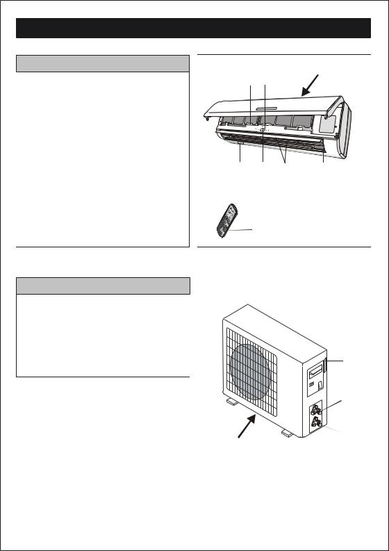
NAMES OF PARTS
INDOOR UNIT
No. Description
1Front panel
2Air filter
3Optional filter (if installed)
4LED Display
5Signal receiver
6Terminal block cover
7Ionizer generator(if installed)
8Deflectors
9Emergency button
10Indoor unit rating label (Stick position optional)
11Airflow direction louver
12Remote controller
INDOOR UNIT
1 2-3 4-5
 10
10  6
6
11 |
10 |
9 |
8 |
7 |
O N /O F F
12
OUTDOOR UNIT |
13 |
||
No. |
Description |
|
|
13 |
Air outlet grille |
|
|
14 |
Outdoor unit rating label |
|
|
15 |
Terminal block cover |
|
|
16 |
gas valve |
14 |
|
17 |
liquid valve |
||
15 |
|||
|
|
||
|
|
16 |
|
|
|
17 |
|
OUTDOOR UNIT
Note: the above figures are only intended to be a simple diagram of the appliance and may not correspond to the appearance of the units that have been purchased.
4
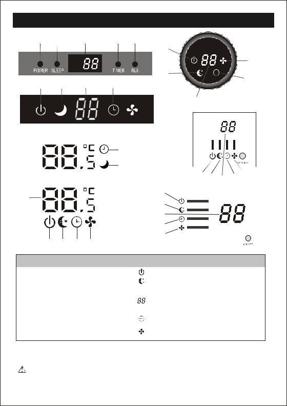
INDOOR UNIT DISPLAY
1 |
2 |
3 |
4 |
5 |
/O |
||
|
|
|
|
1 |
|
|
|
|
|
|
|
5 |
|||
|
|
|
|
2 |
|
|
|
1 |
2 |
3 |
4 |
4 |
|||
5 |
|
|
|
||||
|
|
|
|
|
|
|
|
|
|
|
|
|
3 |
|
|
|
|
|
|
|
|
|
|
|
|
|
|
|
|
|
|
|
|
|
|
|
|
|
|
3 |
|
|
|
|
4 |
|
|
|
|
|
|
|
|
|
|
|
|
|
|
|
|
|
|
|
|
|
|
|
|
|
|
|
|
|
|
|
|||
|
|
|
|
|
|
|
|
|
|
|
|
|
|
|
|
|
|
|
|
|
|
|
|
|
2 |
|
|
|
|
|
|
|
|
|
|
|
|
|
|
|
|
|
|
|
|
|
|
|
|
|
|
5 |
|
|
|
||||
|
|
|
|
|
1 |
|
3 |
|
|
|
|
|
|||||||
|
|
|
|
|
2 |
|
|
4 |
|
|
|
||||||||
3 |
|
|
|
|
1 |
|
|
|
|
|
|
|
|
|
|
|
|
|
|
|
|
|
|
|
|
|
|
|
|
|
|
|
|
|
|
|
|
||
|
|
|
|
2 |
|
|
|
|
|
|
|
|
|
|
|
|
|
|
|
|
|
|
|
|
|
|
|
|
|
|
|
|
|
|
|
|
|
|
|
|
|
|
|
|
3 |
|
|
|
|
|
|
|
|
|
|
|
|
|
|
|
|
|
|
|
4 |
|
|
|
|
|
|
|
|
|
|
|
|
|
|
|
1 |
2 |
3 |
4 |
5 |
|
|
|
|
|
|
|
|
|
|
|
|
|
|
|
|
|
|
|
|
|
|
|
|
|
|
|
|
||||||
|
|
|
|
|
|
|
|
|
|
|
|
|
|
|
|
||||
|
|
|
|
|
|
|
|
|
|
|
|
|
|
|
|
|
|||
No. |
Led |
|
|
|
Function |
|
|
|
|
|
|
|
|
|
|
|
|||
1 |
POWER |
|
|
This symbol appears when the unit is power on |
|||||||||||||||
2 |
SLEEP |
|
|
|
SLEEP mode |
|
|
|
|
|
|
|
|
|
|
|
|||
|
|
|
|
|
|
||||||||||||||
|
|
|
|
|
(1) Lights up during Timer operation when |
||||||||||||||
3 |
Temperature display (if present) |
the air conditioner is operational |
|
|
|
|
|
|
|||||||||||
/Error code |
|
|
(2)Displays the malfunction code when fault |
||||||||||||||||
|
|
|
|||||||||||||||||
|
|
|
|
|
occurs. |
|
|
|
|
|
|
|
|
|
|
|
|||
4 |
TIMER |
|
|
|
Lights up during Timer operation. |
||||||||||||||
The symbol appears when the unit is turned
5 RUN
on, and disappear when the unit is turned off.
The shape and position of switches and indicators may be different according to the model, but their function is the same.
5
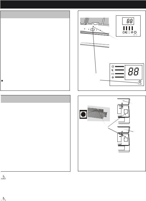
EMERGENCY FUNCTION & AUTO-RESTART FUNCTION
AUTO-RESTART FUNCTION
The appliance is preset auto - restart function by manufacturer. In case of a sudden power failure, the module memorizes the setting conditions before the power failure. when the power restores, the unit restarts automatically with all the previous settings preserved by the memory function.
To deactivate the AUTO-RESTART function ,proceed as follows:
1.Switch the air conditioner off and remove the plug.
2.Press the emergency button meanwhile plug it in.
3.Keep pressing the emergency button for more than 10 seconds until you hear four short beeps from the unit. The AUTO-RESTART function is deactivate.
To activate the AUTO - RESTART function , follow the same procedure until you hear three short beeps from the unit.
|
ON / OFF |
|
POWER SLEEP |
TIMER |
RUN |
|
||
|
|
Emergency |
|
|
button |
Emergency |
||
button |
|
|
EMERGENCY FUNCTION
If the remote controller fails to work or maintenance necessary, proceed as follows:
Open and lift the front panel up to an angle to reach the emergency button.
1.One press of the emergency button(one beep) will lead to the forced COOLING operation
2.Two press of the emergency button within 3 sec (two beeps) will lead to the forced HEATING operation.
3.To switch off the unit , you just need to press the button again ( a single long beep) .
4.After 30 minutes in forced operation , the air conditioner will automatically start working in 23
cooling mode, auto fan speed.
* The FEEL function is described in page 13.
The shape and position of the emergency button may be different according to the model, but their function is the same.
display PCB
|
front panel |
|
ON/OFF |
Emergency |
|
button |
front panel |
|
ON/OFF |
1033A
The emergency button in some models could be on the right part of the unit under the front panel.
Remark: the external static pressure of heat pumps is 0 Pa for all models.
The indoor fan speed during capacity and or efficiency test should be "quick cool" or "quick heat" which can be activated by pressing "TURBO" or "SUPER" button of remote controller; Please contact with the seller in case of failing in activating it.
6
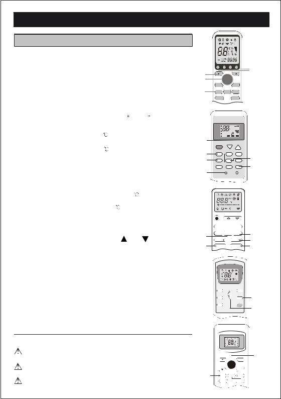
REMOTE CONTROLLER
No. |
Button |
Function |
1 (TEMP UP) Press it to increase temperature / time setting.
2 (TEMP DN) Press it to decrease temperature/ time setting.
3ON/OFF Press it to start or stop operation.
4 |
FAN |
To select the fan speed of auto/low/mid/high |
|
||
5 |
TIMER |
Press it to set auto-off |
timer. |
||
|
|
|
|
|
|
6 |
SLEEP |
To activate the function |
SLEEP |
||
|
|
|
|
||
|
|
In cooling mode,press this button ,the temperature |
|||
7 |
ECO |
will increase 2 on the base of setting temperature |
|||
In heating mode, press |
this button, the temperature |
||||
|
|
||||
|
|
will decrease 2 on the base of setting temperature |
|||
|
|
|
|
||
8 |
MODE |
To select the mode of operation |
|||
|
|
|
|
||
|
|
Press this button to activate / deactivate the Super |
|||
|
|
function which enables the unit to reach the preset |
|||
|
|
temperature in the shortest time. |
|||
9 |
SUPER or TURBO In COOL mode, the unit will give the maximum |
||||
|
|
cooling temperature with 16 ,high fan speed. |
|||
|
|
In HEAT mode, the unit will give the maximum heating |
|||
|
|
temperature with 31 ,high fan speed. |
|||
10 |
SWING |
To activate or deactivate of the movement of the |
|
||
|
|
deflectors. |
|
|
|
|
|
When you press this button,the time will be flic- |
|||
|
|
kering;then through" "and " ",you can adjust |
|||
11 |
CLOCK |
the time(one time you press,one minute you ad- |
|||
just;and if you continue to hold,the time changes |
|||||
|
|
||||
|
|
rapidly ), after adjusting to your required time, |
|||
|
|
please press this button again to fix the time. |
|||
|
|
|
|
||
12 |
DISPLAY |
To switch on/off the LED display |
|||
|
|
|
|
||
13 |
|
To switch - on /off HEALTHY funtion.It is a button |
|||
HEALTHY |
which controls the ionizer or plasma generator only |
||||
|
|
for inverter models. |
|
|
|
14 |
RESET |
To restart REMOTE CONTROLLER |
|||
|
|
||||
15 ANTI-MILDEW To activate the function ANTI-MILDEW |
|||||
The outlooking and some function of remote control may vary according to the model.
The shape and position of buttons and indicators may vary according to the model, but their function is the same.
The unit confirms the correct reception of each press button with a beep.
|
CLOCK |
DISPLAY 3D |
HEALTHY |
13 |
|
|
|
|
|
1 |
|
|
|
12 |
|
|
|
11 |
|
2 |
|
|
|
|
3 |
|
ON/OFF |
|
10 |
4 |
FAN |
|
SWING |
|
5 |
TIMER |
ECO |
SUPER |
9 |
6 |
SLEEP |
|
MODE |
8 |
7 |
|
|
|
|
|
FEEL |
|
|
FAN |
|
|
AUTOQUIET |
SPEED |
|
|
COOL |
C |
POWERFUL |
AIR |
|
DRY |
DELAY |
||
|
FAN |
|
SWING |
|
|
|
|
hr |
|
|
HEAT |
ON |
OFF ON |
|
1HEALTHY TIMER
2ON/OFF
3
8 |
MODE |
TIMER |
ANTI-MILDEW |
15 |
|
|
|
||
4 |
FAN SPEED |
SUPER |
ECO |
9 |
|
|
|
7 |
|
5 |
SWING |
SLEEP |
HEALTHY |
|
6 |
|
|
|
13 |
10 |
|
|
|
|
12 |
DISPLAY |
RESET |
14 |
|
|
|
|||
3 |
|
|
|
|
1 |
|
|
|
|
2 |
|
8 |
|
|
|
|
7 |
MODE |
ECO |
|
TIMER |
5 |
|
4 |
FAN |
SLEEP |
DISPLAY |
12 |
|
6 |
|
|
|
|
|
|
|
|
|
10 |
|
10 |
SWING |
|
SWING |
||
13 |
HEALTHY |
|
TURBO |
9 |
|
|
Feel |
Cool Dry Fan |
Heat |
|
|
|
|
|
C |
Timer |
|
|
|
|
OFF |
|
|
|
|
|
h |
ON |
|
|
|
|
|
Timer |
|
|
Auto Low Mid High Sleep Swing |
|
|||
6 |
|
|
|
|
1 |
SLEEP |
|
|
FAN |
4 |
|
5 |
TIMER |
|
|
SWING |
10 |
8 |
MODE |
|
|
ON/OFF |
3 |
|
|
|
|
|
2 |
|
|
SWING X SUPER SWING Y |
|
||
|
FEEL |
|
|
AUTO |
|
|
COOL |
|
|
HIGH |
|
|
DRY |
|
|
MID |
|
|
FAN |
|
|
LOW |
|
|
HEAT |
|
|
SLEEP |
|
|
|
TIMER ON |
TIMER OFF |
|
|
1 |
|
|
|
|
3 |
|
|
|
MODE |
8 |
|
2 |
|
ON/OFF |
|
5 |
|
|
|
|
TIMER |
||
4 |
FAN |
SWING X |
SWING Y |
6 |
|
|
SUPER |
|
SLEEP |
||
7 |
10 |
 Loading...