


Colour Television |
Chassis: M123A |
1. Technical Specifications, Connections and Chassis Overview
Index:
1.Technical Specifications.
2.Connections.
3.Chassis Overview.
Note:
Below described specifications are not valid for one product, but for the whole product range.
See Product Survey for specific models. Figures can deviate slightly from the actual situation, due to different set executions.
1.1 Technical Specifications
1.1.1 Reception
Tuning system : PLL
Colour systems : NTSC-M
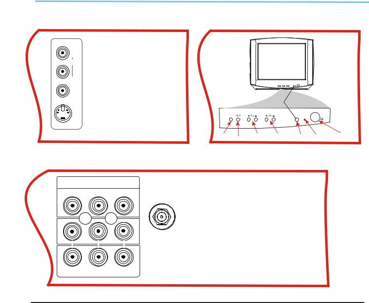
1.2Connections
1.2.1Side Connections and Front Control
Sound systems : FM-mono: FM-stereo A/V connections : NTSC 3.58
Channel selections :TV:2-69,CATV:2-13,A-W, W+1~W+84,A-5~A-1,5A
Aerial input : 75OHM, 1VP-P
1.1.2 Miscellaneous
Audio output : =3W+3W
Mains voltage : AC120V
Mains frequency : 60 Hz
Ambient temperature : + 5 to + 45 deg. C Maximum humidity : 90 %
Power consumption : 80W
Standby Power consumption : <3W
IN1
R
AUDIO
L (MONO)
VIDEO
A/V In
1- Audio R (0.5 Vrms / 1k_)
2- Audio L (0.5 Vrms / 1 k_)
3-Video CVBS (1 Vpp / 75 )
TV/AV |
SENSOR |
STANDBY
POWER
S-VIDEO 4 - S-video (1 Vpp / 75)
TV/AV 


 SENSOR STANDBY POWER
SIDE AV PANEL |
FRONT PANEL |
1.2.2 Rear Connections
|
DVD INPUT |
|
|
DVD Input |
|
|
|
75OHM |
1 |
- Y (1 Vpp / 75 _) |
|
Cr |
Cb |
Y |
ANTENNA |
2 |
- Cb (1 Vpp / 75 _) |
|
|
|
INPUT |
3 |
- Cr (1 Vpp / 75 _) |
|
|
|
|
AV2 In |
|
|
|
|
|
4 |
- Video CVBS (1 Vpp / 75 _) |
|
|
|
In2 |
5 |
- Audio L (0.5 Vrms / 10 k_) |
|
|
|
|
6 |
- Audio R (0.5 Vrms / 10 k_) |
Monitor Out
OUT
7 - Video CVBS (1 Vpp / 75 _)
R- AUDIO- L VIDEO 8 - Audio L (0.5 Vrms / 1 k_)
9 - Audio R (0.5 Vrms / 1 k_)
REAR PANEL
2
Colour Television |
Chassis: M123A |
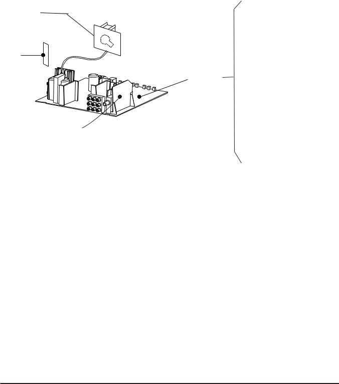
1.3 Chassis Review
CRT PANEL |
|
7.1 |
Power Supplier |
|
|
|
|
|
|
7.2 |
Line Deflection |
Side |
|
7.3 |
Frame Deflection |
AV |
|
||
Panel |
Main |
7.4 Tuner IF |
|
|
Chassis |
||
|
Panel |
|
|
|
|
7.5 MCU, Video IF and |
|
|
|
Sound IF |
|
MSP PANEL |
|
7.6 |
BTSC (Stereo/SAP) |
|
|
Decode |
|
|
|
7.7 |
Video Source |
|
|
|
Switching |
3

Colour Television |
Chassis: M123A |
2.Safety & Maintenance Instructions, Warnings and Notes
2.1Safety Instructions For Repairs
Safety regulations require that during a repair:
--Due to the 'hot' parts of this chassis, the set must be connected to the AC power via an
isolation transformer.
--Safety components, indicated by the symbol _, should be replaced by components identical to the original ones.
--When replacing the CRT, safety goggles must be worn. Safety regulations require that after a repair, the set must be returned in its original condition. Pay particular attention to the following points:
--General repair instruction: as a strict precaution, we advise you to re-solder the solder connections through which the horizontal deflection current is flowing, in particular:
---all pins of the line output transformer (LOT)
---fly-back capacitor(s)
---S-correction capacitor(s)
---line output transistor
---pins of the connector with wires to the deflection coil
---other components through which the deflection current flows.
*Note: This re-soldering is advised to prevent bad connections due to metal fatigue in solder connections and is therefore only necessary for television sets more than two years Old.
--Route the wire trees and EHT cable correctly and secure them with the mounted cable clamps.
--Check the insulation of the AC power cord for external damage.
--Check the strain relief of the AC power cord for proper function, to prevent the cord from touching the CRT, hot components, or heat sinks.
--Check the electrical DC resistance between the AC plug and the secondary side (only for sets that have an isolated power supply). Do this as follows:
1.Unplug the AC power cord and connect a wire between the two pins of the AC plug.
2.Turn on the main power switch (keep the AC power cord unplugged!).
3.Measure the resistance value between the pins of the AC plug and the metal shielding of the tuner or the aerial connection of the set. The reading should be between 4.5 M  and 12 M
  .
.
4.Switch the TV OFF and remove the wire between the two pins of the AC plug.
Check the cabinet for defects, to prevent the possibility of the customer touching any Internal parts.
2.2 Maintenance Instructions
It is recommended to have a maintenance inspection carried out by qualified service personnel. The interval depends on the usage conditions:
---When the set is used under normal circumstances, for example in a living room, the recommended interval is hree to five years.
---When the set is used in an environment with higher dust,grease or moisture levels, for example in a kitchen, the recommended interval is one year.
---The maintenance inspection includes the following actions
1.Perform the 'general repair instruction' noted above.
2.Clean the power supply and deflection circuitry on the chassis.
3.Clean the picture tube panel and the neck of the picture tube.
4
Colour Television Chassis: M123A
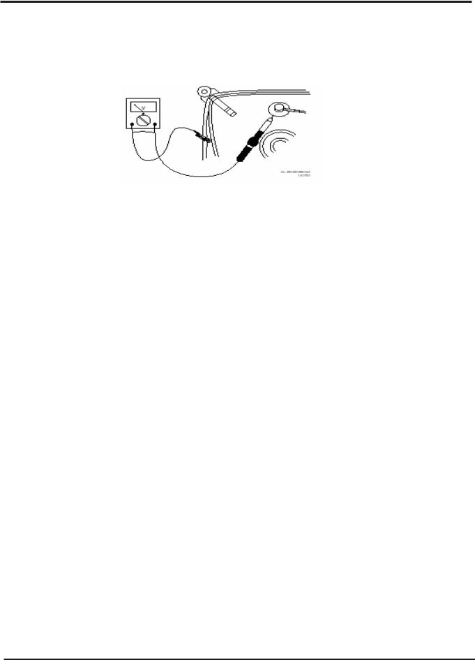
2.3 Warnings
--- In order to prevent damage to ICs and transistors, avoid all high voltage flashovers. In order to prevent damage to the picture tube, use the method shown in Fig. 2-1, to discharge the picture tube. Use a high voltage probe and a multi-meter (position VDC). Discharge until the meter reading is 0 V (after
---- All ICs and many other semiconductors are susceptible to electrostatic discharges (ESD)_ Careless handling during repair can reduce life drastically. When repairing, make sure that you are connected with the same potential as the mass of the set by a wristband with resistance. Keep components and tools also at this potential. Available ESD protection equipment:
---Complete kit ESD3 (small tablemat, wristband, connection box, extension cable, and ground cable)
---Wristband tester 4822 344 13999.
---Together with the deflection unit and any multi-pole unit, flat square picture tubes form an integrated unit. The deflection and the multi-pole units are set optimally at the factory.
Adjustment of this unit during repair is therefore not recommended.
----Be careful during measurements in the high voltage section and on the picture tube. Never replace modules or other components while the unit is switched ON.
----When you align the set, use plastic rather than metal tools. This will prevent any short circuits and the danger of a circuit becoming unstable.
2.4Notes
--- Measure the voltages and waveforms with regard to the chassis (= tuner) ground (), or hot
ground (), depending on the area of circuitry being tested.
----The voltages and waveforms shown in the diagrams are indicative. Measure them in the Service Default Mode (see chapter 5) with a color bar signal and stereo sound (L: 3 kHz, R: 1 kHz unless stated otherwise) and picture carrier at 475.25 MHz (PAL) or 61.25 MHz (NTSC, channel 3).
----Where necessary, measure the waveforms and voltages with () and without () aerial signal. Measure the voltages in the power supply section both in normal operation () and in standby ().
These values are indicated by means of the appropriate symbols.
---- The picture tube panel has printed spark gaps. Each spark gap is connected between an electrode of the picture tube and the Aquadag coating.
--- The semiconductors indicated in the circuit diagram and in the parts lists are completely interchangeable per position with the semiconductors in the unit, irrespective of the type Indication on these semiconductors.
5
Colour Television |
Chassis: M123A |
3.Directions for Use
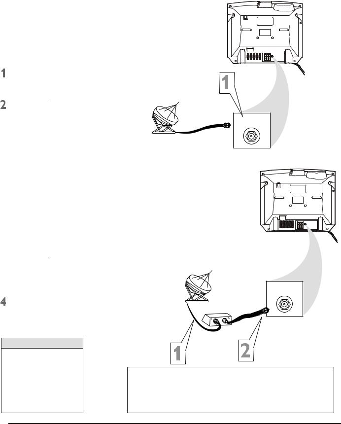
3.1Basic Cable TV Connection
The cable TV signal into your home may be a single cable (75ohm) or may include a cable Box. In either case, the connection to the TV is easy.
If your Cable TV signal comes directly via a 75ohm coaxial cable, use the following steps:
Connect the Cable TV signal to the 75 OHM ANTENNA INPUT jack on the rear of the TV. Screw it
Cable TV company
Plug the TV s power cord into a power outlet and turn on the TV.
Set TV/CATV to CATV as detailed in page11.
Refer to AUTO SEARCH to set up your available channels. Details are on page 12.
75 OHM ANTENNA INPUT
If you have a Cable Box, use the following steps.
 Connect the Cable TV signal to the IN jack on the Cable Box.
 Connect the separate coaxial cable to the OUT jack on the Cable Box and to the 75 OHM ANTENNA INPUT jack on the rear of the TV.
 Plug the TV s power cord into a power outlet and turn on the TV.
Set TV/CATV to CATV as detailed in page11.
Set the TV to channel 3 or 4 (the same as the Channel3/4 switch on your Cable Box if applicable) .
Change channels at the Cable
Cable TV company
75 OHM ANTENNA INPUT
Cable Box
Helpful Hints
An RF coaxial cable (to connect the Cable Box to the TV) may be supplied by the Cable TV company. It is not supplied with the TV.
Y o u c a n c o n n e c t a Satellite Receiver the
Your Cable Box may have separate Audio and Video Out jacks instead. If so, use audio and video cables to connect the AUDIO/VIDEO OUT jacks of the Cable Box to the AUDIO/VIDEO IN 2 jacks on the rear of the TV.
Press the TV/AV on the remote control to set the TV to the
6
Colour Television |
Chassis: M123A |
3.Directions for Use
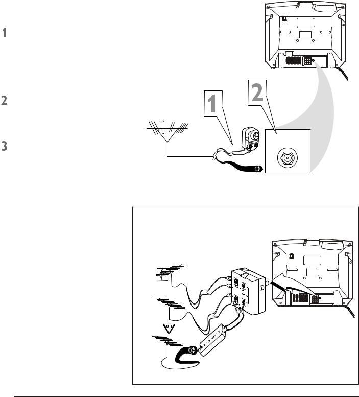
3.2Basic Antenna Connection
A combination antenna receives normal broadcasting channels (VHF2-13 and UHF 14-69). Your connection is easy since you will connect the antenna to the 75OHM ANTENNA INPUT jack on the rear of the TV.
If your antenna has a round cable
(75 ohm) on the end, then you are ready to connect it to the TV. Go to step 2.
If your antenna has flat twin-lead wire (300 ohm), you first need to attach the antenna wire to the screws on a 300 to 75 ohm adapter (not
Push the round end of the adapter or antenna cable onto the 75 OHM ANTENNA INPUT jack on the rear of the TV. If the round end of the antenna cable is threaded, screw it down tight.
Plug the TV s power cord into a power outlet and turn on the TV. Set TV/CATV to CATV as detailed in page11.
Refer to AUTO SEARCH to set up your available channels. Details are on page 12.
75 OHM ANTENNA INPUT
OR
If you have separate UHF and VHF antennas, you need an optional combiner to connect to the TV.
UHFAntenna |
UHF/VHF |
|
Combiner |
VHFAntenna
Rear of TV
75-300 Ohm Adapter
VHFAntenna
7

Colour Television |
Chassis: M123A |
3.Directions for Use
3.3Basic to VCR (ACCESSORY)Connection
The basic Antenna/Cable TV to Accessory (VCR, DVD Player, etc.) to TV connection is shown at right. For other hookups (such as those with Cable Boxes), refer to the owner s manual of the Cable Box or other Accessories.
Connect a yellow video cable to the VIDEO IN 2 jack on the rear of the TV and to the VIDEO OUT jack on your VCR(or other Accessories.)
Connect red and white audio cables to the AUDIO IN 2 jacks(left and right) on the rear of the TV and to the AUDIO OUT jacks on your VCR(or other device.) Match the cable colors to the jack colors.
Turn on the TV and the VCR.
Press the TV/AV button on the TV s remote control until AV2 appears in the upper right corner of the TV screen. When you play material on the VCR, DVD player, etc. that is connected to the AUDIO and VIDEO IN 2 jacks on the rear of the TV, it will appear on the TV on the AV 2 channel.
Helpful Hints
Audio and video cables are not supplied with the TV. Audio cables are usually marked with red and white. Video cables (CVBS) are usually marked with yellow.
You can connect the antenna or Cable TV signal to either the ANTENNA IN jack on your VCR or to the 75 OHM ANTENNA INPUT jack on the TV. If you connect it to the VCR, choose TV channels at the VCR. Connect it to the VCR if you want to record TV programming through VCR.
Your VCR may not have Audio and Video Out jacks, but only an RF or ANTENNA OUT jack. Use an Therefore coaxial cable to connect the VCR s ANTENNA OUT jack t o t h e T V s 7 5 O H M ANTENNA INPUT jack.
There are Component Video In jacks on the rear of the TV. These are labelled DVD Y, Cb and Cr and are red, blue and green. Use these to connect a DVD player that has Component Video Out jacks. This will provide the best picture quality. Use Component Video cables, which are not supplied with the TV.
If you connect the DVD player to the DVD jacks, set the TV to YUV channel to watch DVD s. Press TV/AV button on the remote so YUV appears on the TV screen.
Use either DVD or VIDEO In2 jacks, but do not use both for the same piece of equipment. You only need one video connection per each accessory(DVD player, etc.).
DVD INPUT
Cr |
Cb |
Y |
|
|
|
DVD INPUT
Cr Cb Y
|
|
IN2 |
R |
R |
R |
|
|
|
|
|
OUT |
|
R- AUDIO - L |
VIDEO |
There are AUDIO and VIDEO IN1 jacks at the lower-right corner of the rear of the TV set. To view material playing on equipment connected here, press the TV/AV so VIDEO 1 is on the TV.
There is also an S-VIDEO IN jack in this area. Use S-Video connection if your DVD player, camcorder, etc. has an S-Video Out jack. S-Video provides a clearer picture than the standard CVBS video (the yellow jack). Choose the VIDEO1 channel to view material playing pn equipment connected to the S-VIDEO IN jack.
Use either S-VIDEO IN jack or VIDEO IN1 jacks. Do not use both at the same time for the same piece of equipment. This would interfere with the picture display. If both are used, S-VIDEO IN has priority over the yellow VIDEO In1 jack.
IN1
R
AUDIO
L (MONO)
VIDEO
S-VIDEO
8
Colour Television |
Chassis: M123A |
3.Directions for Use
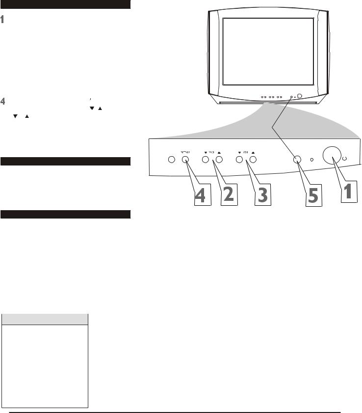
3.4Basic to Antenna Connection
Television
Press POWER to turn on the TV.
 Press VOL.
  to increase the sound level. Press VOL.
 To lower the sound level.
 Press CH.
 or CH.
  to select TV channels.
Press MENU to see the TV |
s on-screen |
|
menu. In the menu, use VOL. |
/ and CH. |
|
/ |
button to make adjustments or |
|
selections. |
|
|
You can |
press MENU on |
either the |
remote control or the front of the TV to access or remove the menu.
Remote control
 Point the remote control toward the remote sensor on the front of the TV when operating the TV with the remote control.
Battery Installation
To load batteries into the remote control:
1.Remove the battery compartment lid on the rear of the remote . Press in the tab, then lift off the lid.
2.Place two AAA batteries in the remote.
Be sure the (+) and (-) ends of the batteries line up correctly (as marked inside the remote).
TV/AV |
SENSOR |
STANDBY
POWER
3. Reattach the battery compartment lid.
Helpful Hints
The channel number will appear briefly when you change channels. Or, press DISPLAY on the remote to see the channel number.
Press TV/AV on the front of the TV to choose AV1/ S- Video, AV2, or YUV.
9
Colour Television |
Chassis: M123A |
3. Directions for Use
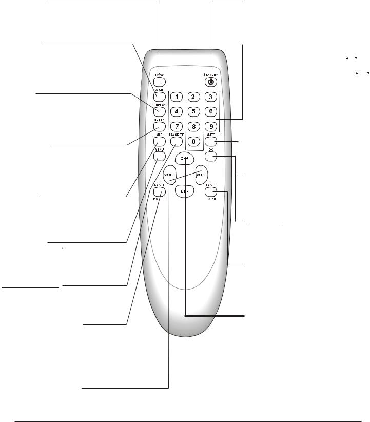
3.5 Remote Control
TV/AV Button
Press to select TV channels or the Audio /Video IN channels(AV1/S-VIDEO, AV2, or YUV).
A/CH Button
In TV mode, press to return to the previous channel.
Note: in AV mode, press A/CH to only enter TV mode.
DISPLAY
Press to see the current channel number on the TV screen. Press again to display the current time on the screen.
Press to remove a menu from the screen.
SLEEP Button
Press to select a time period (120 minutes to 10 minutes in 10 minutes decrements) after which the TV will turn itself off. Details are on page 22.
MTS Button
Press to select a sound mode if available with the TV programming: MONO, STEREO, SAP and MONO+SAP.
Details are on page 31.
MENU Button
Press to see the TV s on-screen menu. Press to go back to the previous menu or to remove a menu from the screen.
FAVORITE Button
Press to browse the channels preset in
Favorite List.
Details are on page 14.
SMART PICTURE Button
Press to select one of the four picture settings(Personal, Movies, Sports, Weak Signal).
Details are on page 17.
STANDBY Button
Press to turn the TV on or off(standby). You also can turn on the TV by pressing the CH(annel) /
/ buttons on the front of the TV.
NUMBER Buttons
Press to select TV channels directly. For
single-digit channels, press two 0 |
first, |
then the number of the channel. |
0 |
For double-digit channels, press |
first, then the two numbers of the channel. For example, to choose channel 45, press the 0 button, then Number 4, then Number 5.
For channels 100 and above, press three number buttons of the channel directly.
(You can select channels above 69 only if you have Cable TV. Make sure TV/CATV is set to CATV. Details are on page 11.)
MUTE Button
Press to cancel or restore the TV sound. Pressing the volume buttons (VOL  or VOL +) also will cancel mute and restore the sound.
OK Button
Within on-screen menu, press to enter some special function, such as Favorite List, etc..
SMART SOUND Button
Press to select one of the four sound settings(Voice, Music, Theatre, or Personal)
Details are on page 29.
CH.(channel)+/- Button
Press to select memorized TV channels.
VOL.(volume)+/- Button
Press to adjust the TV sound level.
10
 Loading...