Tannoy 66D, 6D, 8D User Manual

6D 66D & 8D ACTIVE STUDIO MONITORS
O W N E R S M A N U A L
Tannoy United Kingdom |
T: +44 (0) 1236 420199 |
F: +44 (0) 1236 428230 |
E: enquiries@tannoy.com |
Tannoy North America |
T: (519) 745 1158 |
F: (519) 745 2364 |
E: inquiries@tannoyna.com |
Tannoy Deutschland |
T: (04102) 888 393 |
F: (04102) 888 959 |
E: info@tannoy.com |
|
|
|
|
Tannoy adopts a policy of continuous improvement and product specification is subject to change.
0412 6481

CONTENTS |
|
1.0: IMPORTANT SAFETY INSTRUCTIONS |
3.2 |
Digital SPDIF Input |
|
|
|
1.1 |
Introduction |
||
|
|
|
|
|
|
|
|
2.0: THE BASICS |
2.1 |
Unpacking and visual checks |
|
|
|
|
2.2 |
Preliminary recommendation |
|
|
|
|
|
|
|
|
|
3.0: REVEAL D SERIES FEATURES |
3.1 |
Analog Input |
|
|
|
|
3.3 |
Connecting your speakers |
|
|
|
|
3.4 |
User Controls |
|
|
|
|
|
|
|
|
|
4.0: EQUALISATION POSSIBILITIES |
|
|
|
|
|
|
|
|
|
|
|
5.0: GUIDE TO SETTING THE EQUALISATION |
|
|
|
|
|
|
|
|
|
|
|
6.0: PLACEMENT OF THE SPEAKERS |
6.1 |
Orientation (R6D & R8D) |
|
|
|
|
6.2 |
Positioning (R6D & R8D) |
|
|
|
|
6.3 |
Positioning (R66D) |
|
|
|
|
6.4 |
Speaker Mounting |
|
|
|
|
6.5 |
Bass Ports |
|
|
|
|
|
|
|
|
|
7.0: PERFORMANCE DATA |
Reveal 6D |
||
|
|
|
Reveal 8D |
||
|
|
|
Reveal 66D |
||
|
|
|
|
|
|
|
|
8.0: TECHNICAL SPECIFICATIONS |
|
|
|
|
|
|
|
|
|
|
|
9.0: DIMENSIONS |
|
|
|
|
|
|
|
|
|
|
|
10.0: SERVICING |
6.1 |
Cabinet Finish |
|
|
|
|
6.2 |
Driver Removal |
|
|
|
|
6.3 |
Amplifier Removal |
|
|
|
|
6.4 |
Spare parts |
|
|
|
|
|
|
|
|
|
11.0: WARRANTY |
|
|
|
|
|
|
|
|
|
|
|
12.0: DECLARATION OF CONFORMITY |
|
|
|
|
|
|
|
|
|
2
1.0: IMPORTANT SAFETY INSTRUCTIONS
1. |
Read these instructions. |
The lightning flash with an arrowhead symbol within an |
The exclamation point within an equilateral triangle is |
|
2. |
Keep these instructions. |
|||
equilateral triangle, is intended to alert the user to the |
intended to alert the user to the presence of important |
|||
3. |
Heed all warnings. |
presence of uninsulated “dangerous voltage” within the |
operating and maintenance (servicing) instructions in the |
|
product’s enclosure that may be of sufficient magnitude |
literature accompanying the product. |
to constitute a risk of electric shock to persons.
4.Follow all instructions.
5.Do not use this apparatus near water.
6.Clean only with dry cloth.
7.Do not block any ventilation openings. Install in accordance with manufacturer’s instructions.
8.Do not install near any heat sources such as radiators, heat registers, stoves, or other apparatus (including amplifiers) that produce heat and ensure adequate air circulation around the rear of the product.
9.Do not defeat the safety purpose of the polarised or grounding-type plug. A polarised plug has two blades with one wider than the other. A grounding type plug has two blades and a third grounding prong. The wide blade or the third prong are provided for your safety. If the provided plug does not fit into your outlet, consult an electrician for replacement of the obsolete outlet.
10.Protect the power cord from being walked on or pinched particularly at plugs, wall sockets, and the point where they exit from the apparatus.
11.Only use attachments/accessories specified by the manufacturer.
12.Unplug this apparatus during lightning storms or when unused for long periods of time.
13.Refer all servicing to qualified service personnel. Servicing is required when the apparatus has been damaged in any way, such as power-supply cord or plug is damaged, liquid has been spilled or objects have fallen into the apparatus, the apparatus has been exposed to rain or moisture, does not operate normally, or has been dropped.
14.WARNING: To reduce the risk of fire or electrical shock, this apparatus should not be exposed to rain or moisture and objects filled with liquids, such as vases, should not be placed on this apparatus.
15.To completely disconnect this equipment from the mains, disconnect the power supply cord plug from the wall socket.
16.The mains plug on the power supply cord shall remain readily accessible.
17.SAFETY WARNING: This product design uses amplifier output stages with substantial standing currents for optimal sound quality. Fit and use the protective heat shield when adjusting the feature controls above the heatsink, to prevent contact with uncomfortably hot surfaces when monitoring at continuously high sound pressure levels. Use the small tool provided to adjust the switches in accordance with the instructions in the user manual.
ELECTRICAL REQUIREMENTS
Check that the voltage rating displayed on the rear panel is correct for your area before connecting. If it is incorrect, please refer to your local dealer or authorised service agent, as no user adjustment is provided.
Warning!
•To reduce the risk of fire or electric shock, do not expose this apparatus to rain or moisture.
•Be advised that different operating voltages require the use of different types of line cord and attachment plugs.
•Check the voltage in your area and use the correct type. See table below:
Voltage |
Line plug according to standard |
110-125V |
UL817 and CSA C22.2 no 42. |
220-230V |
CEE 7 page VII, SR section 107-2-D1/IEC 83 page C4. |
240V |
BS 1363 of 1984. Specification for 13A fused plugs and switched and un-switched socket outlets. |
Service
There are no user-serviceable parts inside. Qualified personnel must perform all service. Servicing is required when: -
•The unit has been damaged in any way, such as when the power-supply cord or plug is damaged.
•The unit has been exposed to rain or moisture, or liquid has been spilled into the unit.
•Objects have fallen into the unit.
•The unit does not work properly.
•The unit has been dropped.
EUROPEAN MODELS
A mains cable is supplied with an IEC moulded socket at one end and a moulded mains plug at the other end. Where the moulded plug is fitted with a mains fuse, always replace with the same 5A rated fuse. If the fitted plug is unsuitable for your type of outlet sockets, it should be cut off and disposed of safely, in case it is inserted into a live socket elsewhere. The wires in the mains cable are coloured in accordance with the following code:
GREEN AND YELLOW EARTH |
BLUE NEUTRAL |
BROWN LIVE |
3

AS THE COLOURS OF THE WIRES IN THE MAINS CABLE MAY NOT CORRESPOND WITH THE COLOURED MARKINGS IDENTIFYING THE TERMINALS IN YOUR PLUG, PROCEED AS FOLLOWS:
The wire which is coloured GREEN AND YELLOW must be connected to the terminal in the plug which is marked either by the letter E, the earth safety symbol, or coloured GREEN or GREEN and YELLOW.
The wire which is coloured BLUE must be connected to the terminal in the plug which is marked by the letter N or coloured BLACK
The wire which is coloured BROWN must be connected to the terminal in the plug which is marked by the letter L or coloured RED.
Ensure that the terminals are tightened securely, and no loose strands of wire are present. Ensure cord grip is clamped over outer sheath of cable, rather than over the wires.
FUSE PROTECTION
An additional mains fuse is provided in the IEC power inlet on the back of the loudspeaker, which can only be removed with the power cord unplugged. This must be replaced by a fuse of the same type and ratings (see Specifications or refer to rear panel).
INSTALLATION
Do not install this equipment in an enclosed space. Do not limit free ventilation and movement of air around the back panel. Do not install this equipment in a cupboard with a closed door. Allow for a distance of 150mm (6 inches) of free air space around all sides, top, bottom and the back panel of this product. The user must be able to see the blue coloured front panel of this product when in use.
EMC
This equipment has been tested and found to comply with the limits for a Class B digital device, pursuant to part 15 of the FCC Rules. These limits are designed to provide reasonable protection against harmful interference in a residential installation. This equipment generates uses and can radiate radio frequency energy and, if not installed and used in accordance with the instructions, may cause harmful interference to radio communications. However, there is no guarantee that interference will not occur in a particular installation. If this equipment does cause harmful interference to radio or television reception, which can be determined by turning the equipment off and on, the user is encouraged to try to correct the interference by one or more of the following measures:
Reorient or relocate the receiving antenna.
Increase the separation between the equipment and receiver.
Connect the equipment into an outlet on a circuit different from that to which the receiver is connected. Reorient or coil cables.
If necessary, consult the dealer or an experienced radio/television technician for additional suggestions.
Any cables the user adds to the device must be shielded to be in compliance with the FCC standards. Any unauthorised modification to this device could result in the revocation of the end user’s authority to operate this device.
This device complies with Part 15 of FCC rules. Operation is subject to the following two conditions: (1) This device may not cause harmful interference, and (2) This device must accept any interference received, including interference that may cause undesired operation.
Canada
Industry Canada Class B emission compliance statement. This Class B digital apparatus complies with Canadian ICES-003. Avis de conformite a la reglementation d'Industrie Canada. Cet appareil numerique de classe B est conforme a la norme NMB003 du Canada.
1.1: INTRODUCTION
The Tannoy Reveal Digital range of near field monitoring speakers builds upon the success and worldwide reputation of the famous original Tannoy Reveal Active. Since the launch of the original Tannoy Reveal Active in 1998 there have been significant advances in digital speaker measuring techniques, acoustic CAD design and simulation, and precision manufacturing processes.
The Tannoy Reveal Digital range now provides greater bandwidth, significantly lower levels of distortion, smoother responses, more accurate phase control, and higher sensitivity levels; all within compact cabinet sizes. Also, much has been learnt about the near field listening environment - the effects of boundary walls, acoustic reflections from mixing console surfaces and the acoustic properties of often sparsely prepared PC/Mac post production editing situations.
The Tannoy Reveal Digital range of monitoring speakers can be optimised for far field, mid field and near/close field free space situations right through to far field, mid field and near/close field situations in difficult acoustic spaces such as meter bridge positions, adjacent to walls or reflecting surfaces and space restricted PC/Mac based sound editing environments.
Acoustic space environments are referred to as 4pi, 2pi and pi representing the solid angle in space (steradians) into which the speaker is radiating. These environments are frequently referred to as free space, half space and quarter space listening conditions . The type of acoustic space into which a speaker radiates, defined by nearby solid boundaries, affects the acoustic air load presented to the speaker and so the relative radiating efficiency at various frequencies. In different pi spaces the linearity of the amplitude response changes, especially within the band 50Hz to 800Hz.
Varying distances encountered between the monitors and the listener are generally referred to as far field (greater than 3m or 10 feet), mid field (2 to 3m or 6 to 10 feet), near field (1 to 2m or 3 to 6 feet) and close field (around 0.5m or 1.5 feet). The proximity of the listener to the speaker changes the way the listener perceives the sound balance from the speaker. At large distances from an acoustic source plane waves are perceived. At small distances from an acoustic source the waves appear spherical.
2.0: THE BASICS 
 2.1: UNPACKING AND VISUAL CHECKS
The Reveal 6D’s are packed in pairs and the Reveal 8D and 66D’s are packed singly. To remove the speakers from the carton without damage open the end flaps fully and bend them right back (remember they are packed in pairs). Turn the package upside-down on the floor and lift the carton vertically up to leave the speakers resting on their packing tray. Nothing on or in your speakers should rattle about. Inspect each speaker for signs of transit damage. In the unlikely event of this having occurred inform the carrier and the supplier. Keep all the packaging if damage has occurred, as this will show evidence of excessive handling forces. It is also a good idea to keep the packaging if possible for future transportation.
2.2: PRELIMINARY RECOMMENDATION
Initially we would like to give a word of warning on high sound levels, which these speakers are capable of generating over sustained periods of time. Levels over 95 dB for 8 hours per day can eventually cause permanent hearing loss. Because Tannoy monitors have very low levels of time, amplitude and frequency distortion it is not always obvious that the sound level is high while working with them.
For continuous exposure we recommend the occasional use of a sound level meter capable of integrating the sound level over a period of exposure according to noise control standards. This should be used just to check that noise levels are always within safety limits.
3.0: REVEAL D SERIES FEATURES
A set of DIP switches on the rear panel of each speaker can be set to choose the optimum speaker response for these real life and often difficult situations, so that the frequency response from the speaker is always substantially flat. We are not equalising the room modes due to standing waves or resonant structures, we are equalising the speaker to take account of the varying air load presented by the room and surrounding large structures such as the mixing desk.
The switches are arranged in groups according to their function and each switch can be set to the 'on' (down) or 'off' (up) position in various combinations to achieve a flatter, more balanced response within a wide variety of acoustic spaces and with far, mid, near and close field monitoring positions.
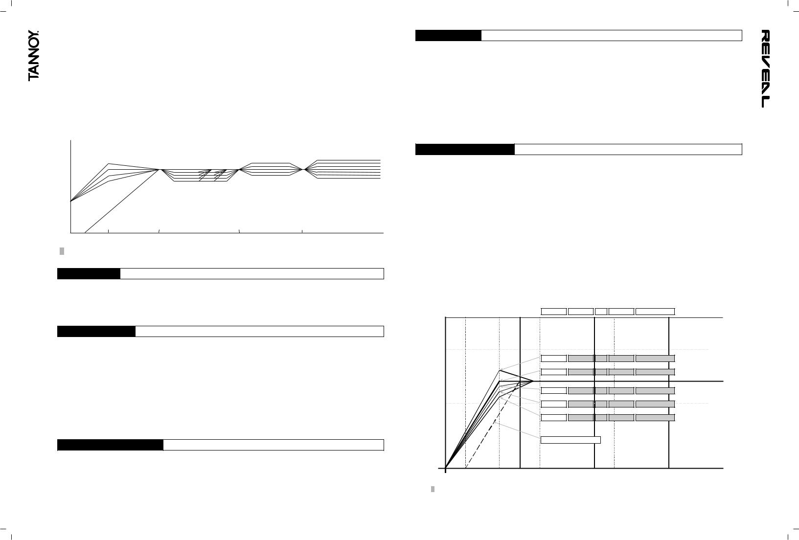
Figure 1 shows the range of equalisation available in the 50Hz to 800Hz region and also shows the degree of trim available in the bass, upper midrange and high frequency areas,
4 |
5 |

An A/V 80Hz high pass filter switch provides instant conversion to 5.1 and higher order systems where a separate subwoofer below 80Hz is required. Filter characteristics are according to the international standards for this setup. This response is also shown diagramatically in Figure 1.
Listening to well recorded male or female spoken word or vocals at the normal listening position is a good way to check and optimise the available settings. Difficult environments and variable listening distances produce varying degrees of boost from the flat position in the 50Hz to 800Hz area. Graphical representations of the responses available by setting the switches are shown below. The linear or flat response positions for the DIP switches are always clearly shown in the diagrams below and also on the rear panel of the speaker.
The Tannoy ActivAssist™ software package is available to help with the DIP switch settings. Using a standard laptop with the microphone and cables supplied in the pack, the performance of the speaker in a particular environment can be assessed and a recommended set of switches set up.
|
|
|
|
+1.5dB |
+3dB |
|
+1.5dB |
Large |
Medium Normal |
+2dB |
|
|
|
||||
0dB |
Flat |
Flat |
|
+0.75dB |
+1dB |
|
Flat |
Flat |
|||
|
-1dB |
-2dB |
|
-0.75dB |
-1dB |
|
-4dB |
|
-1.5dB |
-2dB |
|
|
|
-6dB |
|
-3dB |
-2dB
-8dB
-3dB
( AV 80Hz HiPass on slide switch)
Fig. 1. Full range of equalisation and trim available.
3.1: ANALOG INPUT
XLR: |
2= +ve (hot), 3= -ve (cold), 1= screen, shield or signal ground. |
3 way Jack: |
tip=+ve (hot), ring= -ve (cold), sleeve= screen, shield or signal ground. |
For unbalanced |
XLR connection short pin 1 to pin 3 and use 2= +ve (hot), 3= -ve (ground). |
For unbalanced |
3 way Jack short ring to sleeve and use tip= +ve (hot), sleeve= -ve (ground). |
3.2: DIGITAL SPDIF INPUT
The input impedance is the SPDIF specification at 75 ohms and the 24 bit DAC supports 44.1, 48 and 96kHz sampling rates. Please use a high quality* SPDIF coaxial phono (RCA) cable to connect the source equipment (eg CD player, DAT/ADAT or PC sound card) to one of the speakers. Connect a second (phono to phono) high quality cable from this speaker to the second speaker of the stereo pair. Select whether each speaker converts left channel or right channel audio as appropriate using the switch adjacent to the SPDIF input connector. For true mono requirements set the switch to mono. If volume can be controlled from the source equipment, set the source equipment volume level to minimum and the speaker volume control to maximum (fully clockwise). If volume cannot be controlled by the source equipment (eg a simple CD or DAT etc) set the volume control on the speaker to minimum (fully anticlockwise) to prevent excessive sound levels. The volume control adjusts the analogue level after the DA converters to preserve the full digital dynamic range.
* In order to comply fully with EMC regulations, the SPDIF input and SPDIF thru should be connected using metal-shelled connectors and good quality shielded cable suitable for digital audio.
3.3: CONNECTING YOUR SPEAKERS
Having chosen an appropriate location for your monitors and arranged them accordingly, connect the power cord to the mains socket and turn the power on. The LED on the front panel will now glow red. Push the Tannoy logo on the front panel to operate the switch to bring the amplifier out of standby mode and into operational mode. Set the volume control on the rear panel to zero (fully anticlockwise). Connect the audio signal source (console output) to the input connector (combined XLR/jack socket) or SPDIF at the back of the monitor.
3.4: USER CONTROLS
A/V (80Hz): a switch to the bottom left of the bank of DIP switches sets the system high pass filter to either flat or –6dB at 80Hz. The 80Hz setting is used when the speakers are in combination with a subwoofer for low frequency effects such as Dolby Digital, AC3, DTS etc playback situations. For all other situations set this switch to flat. This response can be seen in Figure 1 above.
Left/Right/Mono: a switch at the bottom left of the bank of DIP switches sets the SPDIF DAC to sense the left, right or combined stereo information (mono) from the digital stream. Set the left hand speaker to ‘Left’ and the right hand speaker to ‘Right’ for 2 channel stereo, or to ‘mono’ for single speaker monitoring.
Analogue/Digital: a switch adjacent to the XLR/Jack combi socket selects whether the speaker is receiving a signal from the balanced/unbalanced analogue input combi socket, or, from the SPDIF phono (RCA) digital input. Both may be connected simultaneously but only one can be selected at any one time.
4.0: EQUALISATION POSSIBILITIES
Note: In the diagrams which follow, the corner frequency shown as 50Hz will vary according to the specification relating to the particular model which has been chosen. Please refer to the detailed specification section at the end of this manual for more details. Smaller models will have a slightly higher corner frequency and larger models will have a lower corner frequency. The diagrams have been prepared to make the visualisation of the EQ possibilities easier to understand. The transitions of the speaker amplitude response bewteen frequency bands will be gradual and not as sharp as the diagrams show. Note the +10dB and -10dB calibrations on the charts. EQ settings should never be at opposite extremes eg -8dB low mid contour with -2dB mids and +3dB highs.
There are 4 basic frequency bands that can be adjusted. The range of adjustment is purposely restricted so that although effective in the majority of environments, it is difficult to set the speaker to have a totally unacceptable response. A 'flat' setting means flat within specification as measured in an anechoic chamber, on axis, under free field conditions in the far field (3 metres away). The frequency bands are:
Bass Corner Frequency: The 'Q' value of the bass unit and cabinet volume alignment can be altered giving +3dB, flat, - 1.5, -3, and -4.5 dB relative to the -3dB point shown in the specification. This provides a degree of boost and cut in the 45Hz to 65Hz area. Figure 2 shows the range of adjustment available together with the DIP switch settings for the first 4 DIP switches. All other DIP switches are shown in the anechoic flat positions.
Diagramatic View of EQ Dip Switches: LF EQ + Av Filter
20 way DIP Switch Bank (4+4+2+4+6) |
LF EQ |
Low Mids |
Hz |
Up Mids |
Highs |
|
|
|||
+10dB |
|
|
|
|
|
|
|
|
|
|
|
|
|
|
1 1 1 1 |
1 1 1 0 |
0 0 |
0 0 0 0 |
0 0 0 0 0 0 |
|
|
|
|
|
|
1 1 1 0 |
1 1 1 0 |
0 0 |
0 0 0 0 |
0 0 0 0 0 0 |
|
|
0dB re 2.8v |
|
|
|
|
|
|
|
|
|
|
@ 1 metre |
|
|
|
|
|
|
|
|
|
|
|
|
|
|
1 1 0 0 |
1 1 1 0 |
0 0 |
0 0 0 0 |
0 0 0 0 0 0 |
|
|
-10dB |
|
|
|
1 0 0 0 |
1 1 1 0 |
0 0 |
0 0 0 0 |
0 0 0 0 0 0 |
|
|
|
|
|
|
0 0 0 0 |
1 1 1 0 |
0 0 |
0 0 0 0 |
0 0 0 0 0 0 |
|
|
|
|
|
|
80Hz AV Filter |
(AV on/off) |
|
|
|
|
|
10Hz |
20Hz |
50Hz |
100Hz |
200Hz |
500Hz |
1Khz |
2kHz |
5kHz |
10kHz |
20kHz |
Fig. 2. Range of adjustment available and settings for the first 4 DIP switches. All other DIPs set to 'Flat'
6 |
7 |
 Loading...