


 Loading...
Sun Fire™ X2100 Server
Getting Started Guide
Sun Microsystems, Inc.
www.sun.com
Part No. 819-3720-12
May 2006, Revision A
Submit comments about this document at: http://www.sun.com/hwdocs/feedback

Copyright © 2006 Sun Microsystems, Inc., 4150 Network Circle, Santa Clara, California 95054, U.S.A. All rights reserved.
Sun Microsystems, Inc. has intellectual property rights relating to technology embodied in the product that is described in this document. In particular, and without limitation, these intellectual property rights may include one or more of the U.S. patents listed at http://www.sun.com/patents and one or more additional patents or pending patent applications in the U.S. and in other countries.
This distribution may include materials developed by third parties.
Parts of the product may be derived from Berkeley BSD systems, licensed from the University of California. UNIX is a registered trademark in the U.S. and in other countries, exclusively licensed through X/Open Company, Ltd.
Sun, Sun Microsystems, the Sun logo, Java, Solaris, Sun Fire, the Solaris logo and Sun Logo are trademarks or registered trademarks of Sun Microsystems, Inc. in the U.S. and other countries.
AMD, Opteron, the AMD logo, and the AMD Opteron logo are trademarks or registered trademarks of Advanced Micro Devices. PostScript and the PostScript logo are trademarks or registered trademarks of Adobe Systems, Incorporated. The Energy Star logo is a registered trademark of EPA.
The OPEN LOOK and Sun(TM) Graphical User Interface was developed by Sun Microsystems, Inc. for its users and licensees. Sun acknowledges the pioneering efforts of Xerox in researching and developing the concept of visual or graphical user interfaces for the computer industry. Sun holds a non-exclusive license from Xerox to the Xerox Graphical User Interface, which license also covers Sun's licensees who implement OPEN LOOK GUIs and otherwise comply with Sun's written license agreements.
Use of any spare or replacement CPUs is limited to repair or one-for-one replacement of CPUs in products exported in compliance with U.S. export laws. Use of CPUs as product upgrades unless authorized by the U.S. Government is strictly prohibited.
DOCUMENTATION IS PROVIDED "AS IS" AND ALL EXPRESS OR IMPLIED CONDITIONS, REPRESENTATIONS AND WARRANTIES, INCLUDING ANY IMPLIED WARRANTY OF MERCHANTABILITY, FITNESS FOR A PARTICULAR PURPOSE OR NON-INFRINGEMENT, ARE DISCLAIMED, EXCEPT TO THE EXTENT THAT SUCH DISCLAIMERS ARE HELD TO BE LEGALLY INVALID.
Copyright © 2006 Sun Microsystems, Inc., 4150 Network Circle, Santa Clara, California 95054, Etats-Unis. Tous droits réservés.
Sun Microsystems, Inc. détient les droits de propriété intellectuels relatifs à la technologie incorporée dans le produit qui est décrit dans ce document. En particulier, et ce sans limitation, ces droits de propriété intellectuelle peuvent inclure un ou plus des brevets américains listés à l'adresse http://www.sun.com/patents et un ou les brevets supplémentaires ou les applications de brevet en attente aux Etats - Unis et dans les autres pays.
Cette distribution peut comprendre des composants développés par des tierces parties.
Des parties de ce produit pourront être dérivées des systèmes Berkeley BSD licenciés par l'Université de Californie. UNIX est une marque déposée aux Etats-Unis et dans d'autres pays et licenciée exclusivement par X/Open Company, Ltd.
Sun, Sun Microsystems, le logo Sun, Java, Solaris, SunTone, The Network is the Computer, We're the dot in .com, iForce, Sun Fire X2100, le logo Solaris et Sun Logo sont des marques de fabrique ou des marques déposées de Sun Microsystems, Inc. aux Etats-Unis et dans d'autres pays.
AMD [*** INSERT TMARK ATTRIBUTION ***]. Opteron [*** INSERT TMARK ATTRIBUTION ***]. Red Hat Linux [*** INSERT TMARK ATTRIBUTION ***]. Suse Linux [*** INSERT TMARK ATTRIBUTION ***]. PostScript [*** INSERT TMARK ATTRIBUTION ***]. Adobe Systems [*** INSERT TMARK ATTRIBUTION ***]. Inc. [*** INSERT TMARK ATTRIBUTION ***]. Le logo PostScript est une marque de fabrique ou une marque déposée de Adobe Systems, Incorporated.
L'interface d'utilisation graphique OPEN LOOK et Sun(TM) a été développée par Sun Microsystems, Inc. pour ses utilisateurs et licenciés. Sun reconnaît les efforts de pionniers de Xerox pour la recherche et le développement du concept des interfaces d'utilisation visuelle ou graphique pour l'industrie de l'informatique. Sun détient une license non exclusive de Xerox sur l'interface d'utilisation graphique Xerox, cette licence couvrant également les licenciés de Sun qui mettent en place l'interface d'utilisation graphique OPEN LOOK et qui, en outre, se conforment aux licences écrites de Sun.
L'utilisation de pieces detachees ou d'unites centrales de remplacement est limitee aux reparations ou a l'echange standard d'unites centrales pour les produits exportes, conformement a la legislation americaine en matiere d'exportation. Sauf autorisation par les autorites des EtatsUnis, l'utilisation d'unites centrales pour proceder a des mises a jour de produits est rigoureusement interdite.
LA DOCUMENTATION EST FOURNIE "EN L'ETAT" ET TOUTES AUTRES CONDITIONS, DECLARATIONS ET GARANTIES EXPRESSES OU TACITES SONT FORMELLEMENT EXCLUES, DANS LA MESURE AUTORISEE PAR LA LOI APPLICABLE, Y COMPRIS NOTAMMENT TOUTE GARANTIE IMPLICITE RELATIVE A LA QUALITE MARCHANDE, A L'APTITUDE A UNE UTILISATION PARTICULIERE OU A L'ABSENCE DE CONTREFACON.
Please
Recycle

Contents
Preface vii
1.System Setup 1–1
1.1 |
Safety and Compliance Information 1–1 |
|
|
|||
1.2 |
Planning the Installation Process |
1–2 |
|
|
||
1.3 |
Package Contents Inventory 1–3 |
|
|
|
||
1.4 |
Installing the Server Into a Rack With Optional Slide-Rails |
1–4 |
||||
|
1.4.1 |
Disassembling the Slide-Rails Before Installation |
1–5 |
|||
|
1.4.2 |
Installing the Mounting Brackets Onto the Server |
|
1–6 |
||
|
1.4.3 |
Attaching the Slide-Rail Assemblies to the Rack |
1–7 |
|||
|
1.4.4 |
Installing the Server Into the Slide-Rail Assemblies |
1–9 |
|||
|
1.4.5 |
Installing the Cable Management Assembly 1–11 |
|
|||
|
1.4.6 |
Attaching and Routing Cables 1–16 |
|
|
||
|
1.4.7 |
Verifying Operation of the Slide-Rails and CMA |
1–17 |
|||
1.5 |
Cabling the Server 1–17 |
|
|
|
|
|
|
1.5.1 |
Interconnecting Servers |
1–19 |
|
|
|
1.6 |
Powering On the Server |
1–20 |
|
|
|
|
1.7 |
Powering Off the Server |
1–21 |
|
|
|
|
1.8 |
Using Serial Console Redirection |
1–22 |
|
|
||
iii
2.Software Installation 2–1
2.1 |
Preparing for Installation 2–1 |
|
|
2.1.1 |
Erasing the Primary Boot Hard Disk 2–3 |
|
2.1.2 |
Setting up the BIOS for Operating System Installation 2–3 |
2.1.2.1Setting up the BIOS for Windows 2003 or Solaris 10 OS 2–3
|
2.1.2.2 |
Setting up the BIOS for a Linux Operating System 2–4 |
2.2 |
Installing the Operating System 2–4 |
|
2.3 |
Running the up2date Utility 2–5 |
|
2.4 |
Installing Drivers and Mounting the Diagnostic Partition 2–6 |
|
|
2.4.1 Installing the Drivers Over a Network 2–6 |
|
|
2.4.1.1 |
Create a Shared Drivers Directory 2–7 |
|
2.4.1.2 |
Copy the Drivers from the Supplemental CD 2–10 |
2.4.1.3Install the Drivers onto the Target Sun Fire X2100 Server 2–11
2.4.2Installing Drivers From the Sun Fire X2100 Server Supplemental CD 2–13
2.4.2.1Installing Linux Operating System Drivers From a CD 2–13
2.4.2.2Installing Solaris 10 OS Operating System Drivers from a CD 2–15
2.4.2.3Installing Windows 2003 Server Operating System
|
|
|
Drivers From a CD 2–16 |
|
|
2.4.2.4 |
Installing Windows 2003 Drivers 2–20 |
3. Setting Up the Preinstalled Software 3–1 |
|||
3.1 |
Solaris 10 Operating System 3–1 |
||
|
3.1.1 |
Solaris 10 Operating System Configuration Overview 3–1 |
|
|
3.1.2 |
Configuration Instructions 3–3 |
|
3.2 |
Java Enterprise System 3–5 |
||
3.3 |
Sun Studio Software 3–7 |
||
iv Sun Fire X2100 Server Getting Started Guide • May 2006
A. Creating Windows Images on a RIS Server and Installing RIS Images |
A–1 |
||||
A.1 |
Creating a RIS Image of Windows 2003 Server 32-bit and Platform |
|
|
||
|
Drivers |
A–2 |
|
|
|
|
A.1.1 Creating the Windows 2003 Server 32-bit Image on the RIS Server |
||||
|
|
A–2 |
|
|
|
|
A.1.2 |
Adding the NVIDA Ethernet Drivers to the Windows Image |
A–3 |
||
|
A.1.3 |
Adding Other Drivers and Modifying Setting Files |
A–4 |
|
|
A.2 |
Creating a RIS Image of Windows 2003 Server, 64-bit, and Platform |
|
|
||
|
Drivers |
A–8 |
|
|
|
|
A.2.1 |
Installing Windows 2003 Server 64-bit onto the RIS Server |
A–8 |
||
|
A.2.2 |
Adding the NVIDA Ethernet Drivers to the Windows Image |
A–9 |
||
|
A.2.3 |
Adding Other Drivers and Modifying Setting Files |
A–10 |
|
|
A.3 |
Installing a RIS Image onto a Client Server A–13 |
|
|
|
|
Contents v
vi Sun Fire X2100 Server Getting Started Guide • May 2006

Preface
The Sun Fire X2100 Server Getting Started Guide provides the information that you need to set up, power on, and configure the server hardware and software.
How This Book Is Organized
This guide is organized into the following chapters:
Chapter 1 contains instructions on unpacking, rackmouting, cabling, and powering on the server.
Chapter 2 describes the operating systems supported by the Sun Fire X2100 Server and the supplemental drivers included with the system.
Chapter 3 explains how to set up the preinstalled Solaris™ 10 Operating System and additional preinstalled software.
vii

Shell Prompts
Shell |
Prompt |
|
|
C shell |
machine-name% |
C shell superuser |
machine-name# |
Bourne shell and Korn shell |
$ |
Bourne shell and Korn shell superuser |
# |
|
|
Typographic Conventions
Typeface* |
Meaning |
Examples |
AaBbCc123 The names of commands, files, and directories; on-screen computer output
AaBbCc123 What you type, when contrasted with on-screen computer output
AaBbCc123 Book titles, new words or terms, words to be emphasized. Replace command-line variables with real names or values.
Edit your.login file.
Use ls -a to list all files.
%You have mail.
%su
Password:
Read Chapter 6 in the User’s Guide.
These are called class options.
You must be superuser to do this.
To delete a file, type rm filename.
* The settings on your browser might differ from these settings.
viii Sun Fire X2100 Server Getting Started Guide • April 2006

Related Documentation
For a description of the document set for the Sun Fire™ X2100 server, see the product's documentation site at the following URL:
http://www.sun.com/products-n-solutions/ hardware/docs/Servers/Workgroup_Servers/x2100/index.html
Translated versions of some of these documents are available at the web site described above in French, German, Japanese, Korean, Simplified Chinese, Traditional Chinese. English documentation is revised more frequently and might be more up-to-date than the translated documentation.
Product Updates, Documentation,
Support, Training, and Warranty URLs
Sun provides updates to documentation, drivers, firmware, and CD-ROM .iso images through the Sun web site. The web site also provides access to technical support and training services. Use the links below to access these Sun services.
Sun Function |
URL |
|
|
Documentation |
http://www.sun.com/documentation/ |
Updates, including firmware, drivers, |
http://www.sun.com/servers/entry/x2100 |
and CD-ROM .iso images |
/downloads.jsp |
Technical support |
http://www.sun.com/service/contacting |
Training |
http://www.sun.com/training/ |
Solaris™ Operating System |
http://docs.sun.com |
documentation |
|
Warranty |
http://www.sun.com/service/support/ |
|
warranty/index.html |
|
|
Preface ix

Third-Party Web Sites
Sun is not responsible for the availability of third-party web sites mentioned in this document. Sun does not endorse and is not responsible or liable for any content, advertising, products, or other materials that are available on or through such sites or resources. Sun will not be responsible or liable for any actual or alleged damage or loss caused by or in connection with the use of or reliance on any such content, goods, or services that are available on or through such sites or resources.
Sun Welcomes Your Comments
Sun is interested in improving its documentation and welcomes your comments and suggestions. You can submit your comments by going to:
http://www.sun.com/hwdocs/feedback
Please include the title and part number of your document with your feedback: Sun Fire X2100 Server Getting Started Guide, 819-3720-13
x Sun Fire X2100 Server Getting Started Guide • April 2006
CHAPTER 1
System Setup
This chapter provides information about the following topics:
■Section 1.1, “Safety and Compliance Information” on page 1-1
■Section 1.2, “Planning the Installation Process” on page 1-2
■Section 1.3, “Package Contents Inventory” on page 1-3
■Section 1.4, “Installing the Server Into a Rack With Optional Slide-Rails” on page 1-4
■Section 1.5, “Cabling the Server” on page 1-17
■Section 1.6, “Powering On the Server” on page 1-20
■Section 1.7, “Powering Off the Server” on page 1-21
■Section 1.8, “Using Serial Console Redirection” on page 1-22
1.1Safety and Compliance Information
Refer to the following document for safety information regarding the Sun Fire™ X2100 Server:
■Important Safety Information for Sun Hardware Systems, 816-7190 (hardcopy document included in the ship kit)
■Sun Fire X2100 Server Safety and Compliance Guide, 819-3723, available on the Sun Fire X2100 Server web site.
1-1
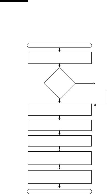
1.2Planning the Installation Process
Use the following flowchart as a process tool to help you install the Sun Fire X2100 Server.
START
Unpack the server and become familiar with the server features.
Yes
Install optional components?
No
See Section 1.3, “Package Contents Inventory” on page 1-3.
Install |
To install additional |
|
components, see the Sun Fire |
||
optional |
||
X2100 Server User Guide or |
||
components. |
||
the component documentation. |
||
|
||
|
|
(Optional) Mount the server in a rack.
Connect the server and external device cables.
Power on the server.
Install the operating system or configure the preinstalled operating system.
Install the supplemental drivers from the Sun Fire X2100 Server Supplemental CD or the network.
See Section 1.4, “Installing the Server Into a Rack With Optional Slide-Rails” on page 1-4.
See Section 1.5, “Cabling the Server” on page 1-17.
See Section 1.6, “Powering On the Server” on page 1-20.
See Section 2.2, “Installing the Operating System” on page 2-4 or Section 3.1, “Solaris 10 Operating System” on page 3-1.
See Section 2.4, “Installing Drivers and Mounting the Diagnostic Partition” on page 2-6.
READY TO WORK!
FIGURE 1-1 Process for Setting Up the Sun Fire X2100 Server
1-2 Sun Fire X2100 Server Getting Started Guide • April 2006

1.3Package Contents Inventory
Carefully unpack all server components from the packing cartons. The following items are packaged with the Sun Fire X2100 Server:
■Sun Fire X2100 Server documentation:
■Sun Fire X2100 Server Setup Guide
■Sun Fire X2100 Server Release Notes
■Important Safety Information for Sun Hardware Systems
■Sun Binary Code License
■Sun Fire X2100 Server Supplemental CD (includes drivers and diagnostics software)
■(Optional) Rackmount kit
The country accessory kit (optional), which includes the power cable, keyboard, and mouse, is packaged separately from the other items.
Chapter 1 System Setup 1-3
1.4Installing the Server Into a Rack With Optional Slide-Rails
Perform the procedures in this section, in the order in which they are listed, to install your server into a four-post rack using the orderable slide-rail options These sliderails are compatible with a wide range of equipment racks that meet the following standards:
■Four-post structure (mounting at both front and rear). Two-post racks are not compatible.
■Rack horizontal opening and unit vertical pitch conforming to ANSI/EIA 310-D-1992 or IEC 60927 standards.
■Distance between front and rear mounting planes between 610 mm and 915 mm (24 inches to 36 inches).
■Clearance depth (to front cabinet door) in front of front rack mounting plane at least 25.4 mm (1 inch).
■Clearance depth (to rear cabinet door) behind front rack mounting plane at least 800mm (31.5 inches), or 700 mm (27.5 inches), without cable management arm.
■Clearance width (between structural supports and cable troughs) between front and rear mounting planes at least 456 mm (18 inches).
Caution – Always load equipment into a rack from the bottom up so that the rack will not become top-heavy and tip over. Deploy your rack’s anti-tilt bar to prevent the rack from tipping during equipment installation.
Caution – Ensure that the temperature in the rack does not exceed the server’s maximum ambient rated temperatures. Consider the total airflow requirements of all equipment installed in the rack, to ensure that the equipment is operated within its specified temperature range.
1-4 Sun Fire X2100 Server Getting Started Guide • April 2006
1.4.1Disassembling the Slide-Rails Before Installation
Use this procedure to remove the mounting brackets from the slide-rail assemblies.
1.Unpack the slide-rails.
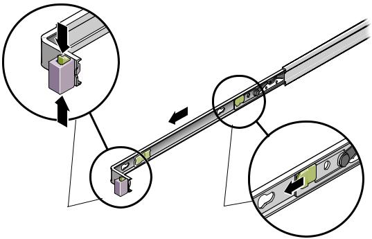
2.Locate the slide-rail lock at the front of one of the slide-rail assemblies, as shown in FIGURE 1-2.
3.Squeeze and hold the tabs at the top and bottom of the lock while you pull the mounting bracket out of the slide-rail assembly, until it reaches the stop. See
FIGURE 1-2.
4.Pull the mounting bracket release button toward the front of the mounting bracket, as shown in FIGURE 1-2, and simultaneously withdraw the mounting bracket from the slide-rail assembly.
5.Repeat for the remaining slide-rail assembly.
Slide-rail lock |
Mounting bracket |
|
release button |
FIGURE 1-2 Disassembling the Slide-Rail Before Installation
Chapter 1 System Setup 1-5
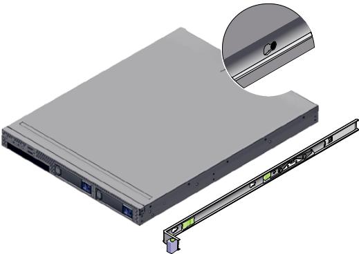
1.4.2Installing the Mounting Brackets Onto the Server
Use this procedure to install the mounting brackets onto the sides of the server.
1.Position a mounting bracket against the chassis so that the slide-rail lock is at the server front, and the three keyed openings on the mounting bracket are aligned with the three locating pins on the side of the chassis.
Mounting-bracket clip
Chassis front
Mounting bracket
Slide-rail lock
FIGURE 1-3 Aligning the Mounting Bracket With the Server Chassis
2.With the heads of the three chassis locating pins protruding though the three keyed openings in the mounting bracket, pull the mounting bracket toward the front of the chassis until the mounting-bracket clip locks into place with an audible click. (See FIGURE 1-3.)
3.Verify that the rear locating pin has engaged the mounting-bracket clip. (See
FIGURE 1-3.)
4. Repeat to install the remaining mounting bracket on the other side of the server.
1-6 Sun Fire X2100 Server Getting Started Guide • April 2006

1.4.3Attaching the Slide-Rail Assemblies to the Rack
Use this procedure to install the slide-rail assemblies to the rack.
1.Position a slide-rail assembly in your rack so that the brackets at each end of the slide-rail assembly are on the outside of the front and rear rack posts. See
FIGURE 1-4.
2.Attach the slide-rail assembly to the rack posts.
The method used to attach the slide-rails varies depending on the type of rack:
■If your rack has threaded mounting holes in the rack posts, first determine whether the threads are metric or standard, and then insert the correct mounting screws through the slide-rail brackets and into the threaded holes.
■If your rack does not have threaded mounting holes, insert the mounting screws through both the slide-rail brackets and rack posts, and then secure them with the caged nuts.
Rack post
Slide-rail assembly bracket on outside of rack post
Slide-rail assembly
FIGURE 1-4 Slide-Rail Assembly Mounting to Rack Post
3. Repeat Step 1 and Step 2 for the remaining slide-rail assembly.
Chapter 1 System Setup 1-7
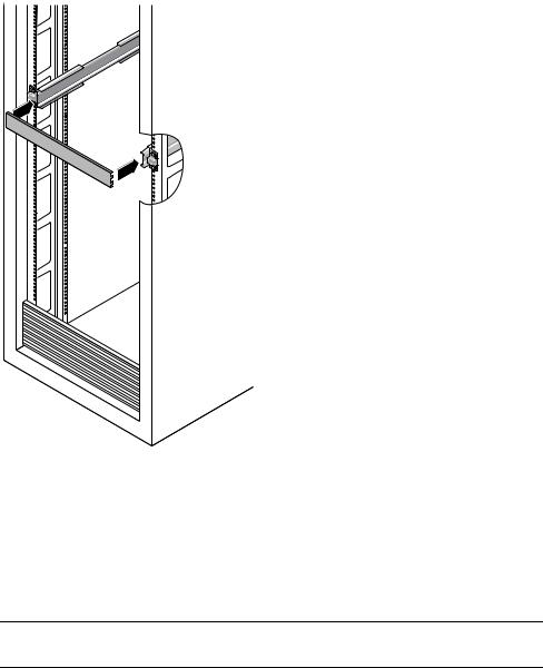
4. From the front of the rack, set the proper width of the rails with spacer. (See
FIGURE 1-5.)
FIGURE 1-5 Setting the Rail Width
5.Tighten the screws on the brackets.
6.Remove the spacer and confirm that the rails are attached tightly to the rack.
7.Repeat Step 4 through Step 6 for rear of the rack.
8.If available, extend the anti-tip foot at the bottom of the rack. (See FIGURE 1-6.)
Caution – If your rack does not have an anti-tip foot, there is some danger of the rack tipping.
1-8 Sun Fire X2100 Server Getting Started Guide • April 2006

FIGURE 1-6 Extending the Anti-tip Foot
1.4.4Installing the Server Into the Slide-Rail Assemblies
Use this procedure to install the server chassis, with mounting brackets, into the slide-rail assemblies that are mounted to the rack.
Caution – This procedure requires a minimum of two people because of the weight of the server. Attempting this procedure alone could result in equipment damage or personal injury.
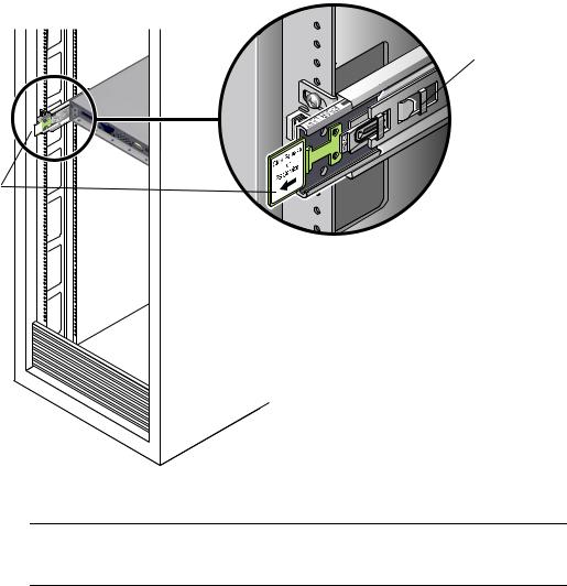
1.Push the slide-rails into the slide-rail assemblies as far as possible.
2.Raise the server so that the rear ends of the mounting brackets are aligned with the slide-rail assemblies that are mounted in the equipment rack. See FIGURE 1-7.
3.Insert the mounting brackets into the slide-rails, and then push the server into the rack until the mounting brackets encounter the slide-rail stops (approximately 12 inches, or 30 cm).
Chapter 1 System Setup 1-9

Mounting bracket inserted into slide-rail
Slide-rail |
Slide-rail |
release |
assembly |
button |
mounted on |
|
rack post |
FIGURE 1-7 Inserting the Server With Mounting Brackets Into the Slide-Rails
4.Simultaneously pull and hold the slide-rail release buttons on each mounting bracket while you push the server into the rack. (See FIGURE 1-7.) Continue pushing until the slide-rail locks on the front of the mounting brackets engage the slide-rail assemblies.
You will hear an audible click.
Caution – Before continuing to the next procedure, verify that the server is securely mounted in the rack and that the slide-rail locks are engaged with the mounting brackets.
1-10 Sun Fire X2100 Server Getting Started Guide • April 2006
1.4.5Installing the Cable Management Assembly
Use this procedure to install an optional cable management assembly (CMA).
1.Unpack the CMA parts.
2.Take the CMA to the back of the equipment rack and ensure that you have adequate room to work around the back of the server.
Note – References to “left” or “right” in this procedure assume that you are facing the back of the equipment rack.
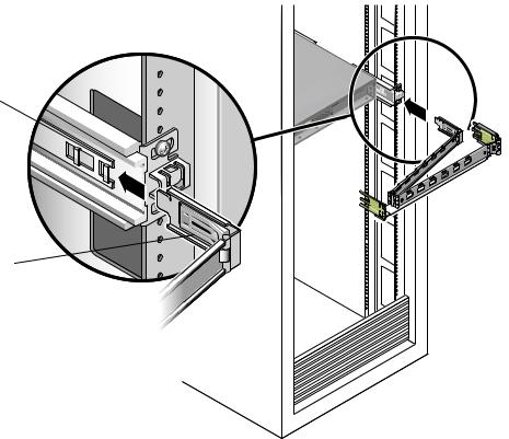
3.Locate the CMA rail extension and insert it into the left slide-rail until the extension locks into place with an audible click. (See FIGURE 1-8.)
The CMA rail extension might be taped to the CMA assembly.
Left slide-rail
CMA rail extension
FIGURE 1-8 Inserting the CMA Rail Extension Into the Back of the Left Slide-Rail
Chapter 1 System Setup 1-11
4. Verify that the CMA rail extension engages the slide-rail, as shown in FIGURE 1-9.
Left slide-rail
CMA rail extension
FIGURE 1-9 Detail of CMA Rail Extension Inserted Into the Left Slide-Rail
Caution – Support the CMA in the remaining installation steps. Do not allow the assembly to hang by its own weight until it is secured by all three of the attachment points.
1-12 Sun Fire X2100 Server Getting Started Guide • April 2006
5.Insert the CMA’s mounting bracket connector into the right slide-rail until the connector locks into place with an audible click. (See FIGURE 1-10.)
Right slide-rail
CMA mounting bracket
FIGURE 1-10 Inserting the CMA Mounting Bracket Into the Back of the Right Slide-Rail
Chapter 1 System Setup 1-13

6.Insert the right CMA slide-rail connector into the right slide-rail assembly until the connector locks into place with an audible click. (See FIGURE 1-11.)
Right sliderail assembly
CMA slide-rail connector
FIGURE 1-11 Inserting CMA Slide-Rail Connector Into Back of Right Slide-Rail Assembly
1-14 Sun Fire X2100 Server Getting Started Guide • April 2006
Loading...