


 Loading...
Sun BladeTM T6320 Server Module
Service Manual
Sun Microsystems, Inc.
www.sun.com
Part No. 820-2386-12
June 2009, Revision A
Submit comments about this document at: http://www.sun.com/hwdocs/feedback

Copyright © 2009 Sun Microsystems, Inc., 4150 Network Circle, Santa Clara, California 95054, U.S.A. All rights reserved.
Sun Microsystems, Inc. has intellectual property rights relating to technology embodied in the product that is described in this document. In particular, and without limitation, these intellectual property rights may include one or more of the U.S. patents listed at http://www.sun.com/patents and one or more additional patents or pending patent applications in the U.S. and in other countries.
This distribution may include materials developed by third parties.
Parts of the product may be derived from Berkeley BSD systems, licensed from the University of California. UNIX is a registered trademark in the U.S. and in other countries, exclusively licensed through X/Open Company, Ltd.
Sun, Sun Microsystems, the Sun logo, Java, Solaris and Sun Blade are trademarks or registered trademarks of Sun Microsystems, Inc., and its subsidiaries, in the U.S. and other countries.
All SPARC trademarks are used under license and are trademarks or registered trademarks of SPARC International, Inc. in the U.S. and other countries. Products bearing SPARC trademarks are based upon architecture developed by Sun Microsystems, Inc.
Products covered by and information contained in this service manual are controlled by U.S. Export Control laws and may be subject to the export or import laws in other countries. Nuclear, missile, chemical biological weapons or nuclear maritime end uses or end users, whether direct or indirect, are strictly prohibited. Export or reexport to countries subject to U.S. embargo or to entities identified on U.S. export exclusion lists, including, but not limited to, the denied persons and specially designated nationals lists is strictly prohibited.
Use of any spare or replacement CPUs is limited to repair or one-for-one replacement of CPUs in products exported in compliance with U.S. export laws. Use of CPUs as product upgrades unless authorized by the U.S. Government is strictly prohibited.
DOCUMENTATION IS PROVIDED "AS IS" AND ALL EXPRESS OR IMPLIED CONDITIONS, REPRESENTATIONS AND WARRANTIES, INCLUDING ANY IMPLIED WARRANTY OF MERCHANTABILITY, FITNESS FOR A PARTICULAR PURPOSE OR NON-INFRINGEMENT, ARE DISCLAIMED, EXCEPT TO THE EXTENT THAT SUCH DISCLAIMERS ARE HELD TO BE LEGALLY INVALID.
Copyright © 2009 Sun Microsystems, Inc., 4150 Network Circle, Santa Clara, California 95054, Etats-Unis. Tous droits réservés.
Sun Microsystems, Inc. détient les droits de propriété intellectuels relatifs à la technologie incorporée dans le produit qui est décrit dans ce document. En particulier, et ce sans limitation, ces droits de propriété intellectuelle peuvent inclure un ou plus des brevets américains listés à l’adresse http://www.sun.com/patents et un ou les brevets supplémentaires ou les applications de brevet en attente aux Etats - Unis et dans les autres pays.
Cette distribution peut comprendre des composants développés par des tierces parties.
Des parties de ce produit pourront être dérivées des systèmes Berkeley BSD licenciés par l’Université de Californie. UNIX est une marque déposée aux Etats-Unis et dans d’autres pays et licenciée exclusivement par X/Open Company, Ltd.
Sun, Sun Microsystems, le logo Sun, Java, Solaris et Sun Blade sont des marques de fabrique ou des marques déposées de Sun Microsystems, Inc., et ses filiales, aux Etats-Unis et dans d’autres pays.
Toutes les marques SPARC sont utilisées sous licence et sont des marques de fabrique ou des marques déposées de SPARC International, Inc. aux Etats-Unis et dans d’autres pays. Les produits portant les marques SPARC sont basés sur une architecture développée par Sun Microsystems, Inc.
Ce produit est soumis à la législation américaine en matière de contrôle des exportations et peut être soumis à la règlementation en vigueur dans d’autres pays dans le domaine des exportations et importations. Les utilisations , ou utilisateurs finaux, pour des armes nucléaires, des missiles, des armes biologiques et chimiques ou du nucléaire maritime, directement ou indirectement, sont strictement interdites. Les exportations ou reexportations vers les pays sous embargo américain, ou vers des entités figurant sur les listes d’exclusion d’exportation américaines, y compris, mais de manière non exhaustive, la liste de personnes qui font objet d’un ordre de ne pas participer, d’une façon directe ou indirecte, aux exportations des produits ou des services qui sont régis par la législation américaine en matière de contrôle des exportations et la liste de ressortissants spécifiquement désignés, sont rigoureusement interdites. L’utilisation de pièces détachées ou d’unités centrales de remplacement est limitée aux réparations ou à l’échange standard d’unités centrales pour les produits exportés, conformément à la législation américaine en matière d’exportation. Sauf autorisation par les autorités des Etats-Unis, l’utilisation d’unités centrales pour procéder à des mises à jour de produits est rigoureusement interdite.
LA DOCUMENTATION EST FOURNIE "EN L’ETAT" ET TOUTES AUTRES CONDITIONS, DECLARATIONS ET GARANTIES EXPRESSES OU TACITES SONT FORMELLEMENT EXCLUES, DANS LA MESURE AUTORISEE PAR LA LOI APPLICABLE, Y COMPRIS NOTAMMENT TOUTE GARANTIE IMPLICITE RELATIVE A LA QUALITE MARCHANDE, A L’APTITUDE A UNE UTILISATION PARTICULIERE OU A L’ABSENCE DE CONTREFACON.

Contents
Preface ix |
|
|
|
|
1. Sun Blade T6320 Server Module Product Description |
1–1 |
|||
1.1 |
Component Overview 1–1 |
|
|
|
|
1.1.1 |
Multicore Processor Information |
1–9 |
|
1.2 |
Support for RAID Storage Configurations |
1–10 |
|
|
|
1.2.1 |
Sun Blade RAID 5 Expansion Module |
1–11 |
|
|
1.2.2 |
Sun Blade RAID 0/1 G2 Expansion Module 1–11 |
||
1.3 |
Finding the Serial Number |
1–11 |
|
|
|
1.4 |
Additional Service Related Information |
1–14 |
|||
2. Sun Blade T6320 Server Module Diagnostics |
2–1 |
|
|||
2.1 |
Sun Blade T6320 Server Module Diagnostics Overview 2–2 |
||||
2.2 |
Memory Configuration and Fault Handling |
2–7 |
|||
|
2.2.1 FB-DIMM Configuration Guidelines |
2–7 |
|||
|
2.2.1.1 |
DIMM Installation Rules |
2–8 |
||
|
2.2.1.2 |
Memory Fault Handling |
2–11 |
||
|
2.2.1.3 |
Troubleshooting Memory Faults 2–11 |
|||
2.3 |
Interpreting System LEDs |
2–12 |
|
|
|
|
2.3.1 Front Panel LEDs and Buttons |
2–12 |
|
||
iii
|
2.3.2 |
Ethernet Port LEDs 2–16 |
|
|
2.4 |
Using ILOM for Diagnosis and Repair Verification 2–16 |
|
||
2.5 |
Using the ILOM Web Interface For Diagnostics 2–18 |
|
||
|
2.5.1 |
Changing POST Settings With the ILOM Web Interface |
2–19 |
|
|
2.5.2 |
Changing POST Settings With the ILOM CLI 2–21 |
|
|
|
2.5.3 |
Displaying System Faults 2–21 |
|
|
|
|
2.5.3.1 |
Viewing Fault Status Using the ILOM Web Interface 2– |
|
|
|
|
22 |
|
|
|
2.5.3.2 |
Viewing Fault Status Using the ILOM CLI 2–23 |
|
|
2.5.4 |
Displaying the Environmental Status with the ILOM CLI |
2–24 |
|
2.5.5Displaying the Environmental Status and Sensor Readings with the
ILOM Web Interface 2–25
2.5.6 Displaying FRU Information 2–27
2.5.6.1Using the ILOM Web Interface to Display FRU Information 2–27
2.5.6.2 |
Using the CLI to Display FRU Information 2–28 |
2.6Running POST 2–31
2.6.1 Controlling How POST Runs |
2–31 |
|
||
2.6.2 |
Changing POST Parameters |
2–34 |
|
|
|
2.6.2.1 |
Using the Web Interface to Change POST Parameters |
||
|
|
2–34 |
|
|
|
2.6.2.2 |
Using the CLI to Change POST Parameters 2–37 |
||
2.6.3 |
Interpreting POST Messages |
2–38 |
|
|
2.6.4 |
Clearing POST Detected Faults 2–39 |
|
||
|
2.6.4.1 |
Clearing Faults With the Web Interface |
2–40 |
|
|
2.6.4.2 |
Clearing Faults With the ILOM CLI 2–41 |
||
|
2.6.4.3 |
Clearing Faults Manually with ILOM |
2–42 |
|
|
2.6.4.4 |
Clearing Hard Drive Faults 2–42 |
|
|
2.7 Using the Solaris Predictive Self-Healing Feature 2–42
iv Sun Blade T6320 Server Module Service Manual • June 2009
2.7.1Identifying Faults With the fmadm faulty and fmdump Commands 2–43
|
|
2.7.1.1 |
Using the fmadm faulty Command 2–43 |
||
|
|
2.7.1.2 |
Using the fmdump Command |
2–44 |
|
|
2.7.2 |
Clearing PSH Detected Faults |
2–45 |
|
|
|
2.7.3 |
Clearing the PSH Fault From the ILOM Logs 2–46 |
|||
2.8 |
Collecting Information From Solaris OS Files and Commands 2–47 |
||||
|
2.8.1 |
Checking the Message Buffer |
2–47 |
|
|
|
2.8.2 |
Viewing the System Message Log Files |
2–48 |
||
2.9 |
Managing Components With Automatic System Recovery Commands 2– |
||||
|
48 |
|
|
|
|
2.9.1Displaying System Components With the show /SYS Command 2–50
2.10 |
Exercising the System With SunVTS |
2–51 |
|
|
|
|||
|
2.10.1 |
Checking SunVTS Software Installation |
2–51 |
|
|
|||
|
2.10.2 |
Exercising the System Using SunVTS Software |
2–52 |
|
||||
|
2.10.3 |
Steps for Exercising the System With SunVTS Software |
2–52 |
|||||
2.11 |
Resetting the Password to the Factory Default |
2–56 |
|
|
||||
|
2.11.1 |
To Reset the Root Password to the Factory Default 2–56 |
|
|||||
3. Replacing Hot-Swappable and Hot-Pluggable Components |
3–1 |
|
||||||
3.1 |
Hot-Pluggable Hard Drives |
3–1 |
|
|
|
|
|
|
3.2 |
Hot-Plugging a Hard Drive |
3–1 |
|
|
|
|
|
|
|
3.2.1 |
Rules for Hot-Plugging |
3–2 |
|
|
|
|
|
|
3.2.2 |
Removing a Hard Drive |
3–2 |
|
|
|
||
|
3.2.3 |
Replacing a Hard Drive or Installing a New Hard Drive |
3–4 |
|||||
3.3 |
Adding PCI ExpressModules |
3–5 |
|
|
|
|
||
4. Replacing Cold-Swappable Components |
4–1 |
|
|
|
||||
4.1 |
Safety Information 4–1 |
|
|
|
|
|
|
|
Contents v
4.1.1Safety Symbols 4–2
|
4.1.2 Electrostatic Discharge Safety 4–2 |
|
|
|
4.1.2.1 |
Using an Antistatic Wrist Strap 4–2 |
|
|
4.1.2.2 |
Using an Antistatic Mat |
4–3 |
4.2 |
Common Procedures for Parts Replacement |
4–3 |
|
4.2.1Required Tools 4–3
4.2.2 Shutting Down the System 4–3
4.2.3Using the ILOM Web Interface to Shut Down the Server Module 4–4
|
4.2.4 |
Using the ILOM CLI to Shut Down the Server Module |
4–5 |
||||
4.3 |
Removing and Replacing DIMMs 4–10 |
|
|
|
|||
|
4.3.1 |
Removing the DIMMs |
4–10 |
|
|
|
|
|
4.3.2 |
Replacing the DIMMs |
4–14 |
|
|
|
|
|
|
4.3.2.1 |
Verifying DIMM Installation |
4–15 |
|
||
4.4 |
Removing and Replacing the Service Processor |
4–15 |
|
||||
|
4.4.1 |
Removing the Service Processor |
4–15 |
|
|
||
|
4.4.2 |
Replacing the Service Processor |
4–17 |
|
|
||
4.5 |
Removing and Replacing the Battery on the Service Processor |
4–18 |
|||||
|
4.5.1 |
Replacing the Battery on the Service Processor 4–19 |
|
||||
4.6 |
Replacing or Installing the Sun Blade RAID 5 Expansion Module 4–20 |
||||||
|
4.6.1 |
Installing the RAID 5 Expansion Module |
4–21 |
|
|||
|
4.6.2 |
Configuring the RAID 5 Expansion Module 4–24 |
|
||||
|
4.6.3 |
Creating a Bootable Array With the RAID 5 Expansion Module 4– |
|||||
|
|
25 |
|
|
|
|
|
4.6.4 Additional Information 4–25
4.7Removing and Replacing the Sun Blade G2 RAID 0/1 Expansion Module 4–25
4.7.1 |
Replacing the RAID 0/1 Expansion Module 4–26 |
4.7.2 |
Verifying the RAID 0/1 Expansion Module Installation 4–27 |
4.8 Finishing Component Replacement 4–28
vi Sun Blade T6320 Server Module Service Manual • June 2009
|
4.8.1 |
Replacing the Cover |
4–28 |
|
|
|||
|
4.8.2 |
Reinstalling the Server Module in the Chassis |
4–28 |
|
||||
A. Specifications |
A–1 |
|
|
|
|
|
||
A.1 |
Physical Specifications |
A–1 |
|
|
|
|
||
|
A.1.1 |
System Environmental Specifications A–2 |
|
|
||||
A.2 |
Motherboard Block Diagram |
A–3 |
|
|
||||
B. Creating a Bootable Array With the Sun Blade RAID 5 Expansion Module |
B–1 |
|||||||
B.1 |
About Creating a Bootable Array on a SPARC System |
B–2 |
|
|||||
B.2 |
Creating a Bootable Array Task Map B–2 |
|
|
|||||
B.3 |
Modifying the Miniroot Directory On the Install Server |
B–3 |
|
|||||
B.4 |
Modifying the Product Installation Directory on the Install Server B–5 |
|||||||
B.5 |
Building a Logical Drive On Which to Install the Solaris OS B–6 |
|
||||||
B.6 |
Next Steps |
B–11 |
|
|
|
|
|
|
|
B.6.1 |
Additional Information |
B–12 |
|
|
|||
C. Installing the Solaris OS and the RAID 5 Expansion Module Driver C–1 |
|
|||||||
C.1 |
Preparing to Install the Solaris OS C–1 |
|
|
|||||
C.2 |
Installing the RAID 5 Expansion Module Driver With the Solaris OS |
C–2 |
||||||
C.3 |
Next Steps |
C–4 |
|
|
|
|
|
|
|
C.3.1 |
Additional Information |
C–4 |
|
|
|||
D. XVR-50 Graphics Accelerator |
D–1 |
|
|
|
|
|||
D.1 |
Features D–1 |
|
|
|
|
|
||
D.2 |
Video Formats D–2 |
|
|
|
|
|
||
D.3 |
Sun OpenGL for Solaris Software |
D–3 |
|
|
||||
D.4 |
Man Pages |
D–3 |
|
|
|
|
|
|
D.5 |
Optional Video Output |
D–4 |
|
|
|
|
||
D.6 |
Default Color Depth D–4 |
|
|
|
|
|||
Contents vii
D.7 |
Checking Device Configuration D–5 |
D.8 |
HD15 Video Output Port D–6 |
Index |
Index–1 |
viii Sun Blade T6320 Server Module Service Manual • June 2009

Preface
The Sun BladeTM T6320 Server Module Service Manual provides information to aid in diagnosing hardware problems and describes how to replace components. This manual also describes how to add components such as hard drives and memory.
This manual is written for technicians, service personnel, and system administrators who service and repair computer systems. The person qualified to use this manual:
■Can open a system chassis, and can identify and replace internal components.
■Understands the Solaris™ Operating System and the command-line interface.
■Has superuser privileges for the system being serviced.
■Understands typical hardware troubleshooting tasks.
Using UNIX Commands
This document might not contain information about basic UNIX® commands and procedures such as shutting down the system, booting the system, and configuring devices. Refer to the following for this information:
■Software documentation that you received with your system
■Solaris Operating System documentation, which is at: http://docs.sun.com
ix

Typographic Conventions
Typeface* |
Meaning |
Examples |
AaBbCc123 The names of commands, files, and directories; on-screen computer output
AaBbCc123 What you type, when contrasted with on-screen computer output
AaBbCc123 Book titles, new words or terms, words to be emphasized. Replace command-line variables with real names or values.
Edit your.login file.
Type ls -a to list all files.
%You have mail.
%su
Password:
Read Chapter 6 in the User’s Guide.
These are called class options.
You must be superuser to do this.
To delete a file, type rm filename.
* The settings on your browser might differ from these settings.
Shell Prompts
Shell |
Prompt |
|
|
C shell |
machine-name% |
C shell superuser |
machine-name# |
Bourne shell and Korn shell |
$ |
Bourne shell and Korn shell superuser |
# |
|
|
Accessing Sun Documentation
You can view, print, or purchase a broad selection of Sun documentation, including localized versions, at:
http://docs.sun.com/app/docs/prod/blade.t6320
To find other product documents, search on the software name or book title.
x Sun Blade T6320 Server Module Service Manual • June 2009
Document Title |
Description |
|
|
Sun Blade T6320 Server Module Product Notes, 820-2383
Sun Blade T6320 Server Module Installation
Guide, 820-2384
Sun Integrated Lights Out Manager 2.0 Supplement for Sun Blade T6320 Server Modules, 820-2546
Sun Blade T6320 Server Module Safety and
Compliance Manual, 820-2387
Important late-breaking information about the server module and related software.
Basic information about installing, powering on and installing software. If you purchased hard drives with preinstalled software you can also find information here:
http://www.sun.com/software/preinstall
ILOM information specific to the UltraSPARC and the Sun Blade T6320 server module. Provides command comparisons of the ALOM CMT and ILOM CLI command sets.
Important safety information for the Sun Blade T6320 server module.
Chassis Documentation (Refer to the documents for your specific modular system chassis.)
Integrated Lights Out Manager ILOM |
ILOM information specific to the modular system chassis. |
Administration Guide |
|
Modular System Product Notes |
Late-breaking information about the chassis and related |
|
software. |
Modular System Service Manual |
Component removal and replacement procedures, diagnostics |
|
information and specifications. |
Software Documentation |
|
Sun Integrated Lights out Manager 2.0 User’s |
Advanced Lights Out Manager (ALOM) CMT software. |
Guide, 820-1188 |
|
Configuring Jumpstart Servers to Provision Sun |
Configuring JumpStart servers. |
x86-64 Systems, 819-1962-10 |
|
Solaris 10 8/07 Installation Guide: Network- |
Setting up network-based installations and JumpStart servers. |
Based Installations |
|
Sun VTS 6.4 User’s Guide, 820-1669 |
Testing the server module, and creating custom hardware tests. |
Beginner’s Guide to LDoms: Understanding and |
Learning about LDoms principles. |
Deploying Logical Domains, 820-0832 |
|
Solaris Operating System documentation |
All information related to Solaris system administration |
|
commands and features. Go to http://www.docs.sun.com |
|
|
Preface xi

Third-Party Web Sites
Sun is not responsible for the availability of third-party web sites mentioned in this document. Sun does not endorse and is not responsible or liable for any content, advertising, products, or other materials that are available on or through such sites or resources. Sun will not be responsible or liable for any actual or alleged damage or loss caused by or in connection with the use of or reliance on any such content, goods, or services that are available on or through such sites or resources.
Documentation, Support, and Training
Sun Function |
URL |
|
|
Documentation |
http://docs.sun.com/app/docs/prod/blade.t6320 |
Support |
http://www.sun.com/support/ |
Training |
http://www.sun.com/training/ |
Preinstalled Software |
http://www.sun.com/software/preinstall/ |
|
|
Sun Welcomes Your Comments
Sun is interested in improving its documentation and welcomes your comments and suggestions. You can submit your comments by going to:
http://www.sun.com/hwdocs/feedback/
Please include the title and part number of your document with your feedback:
Sun Blade T6320 Server Module Service Manual, part number 820-2386.
xii Sun Blade T6320 Server Module Service Manual • June 2009

CHAPTER 1
Sun Blade T6320 Server Module
Product Description
This chapter provides an overview of the features of the Sun Blade TM T6320 server module. (A server module is also known as a “blade.”)
The following topics are covered:
■Section 1.1, “Component Overview” on page 1-1
■Section 1.2, “Support for RAID Storage Configurations” on page 1-10
■Section 1.3, “Finding the Serial Number” on page 1-11
■Section 1.4, “Additional Service Related Information” on page 1-14
1.1Component Overview
FIGURE 1-1, FIGURE 1-2 and FIGURE 1-3 show the main Sun Blade T6320 components and some basic connections to the chassis. For information about connectivity to system fans, PCI ExpressModules, Ethernet modules, and other components, see the chassis documentation at:
http://docs.sun.com/app/docs/prod/blade.t6320
1-1
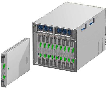
FIGURE 1-1 Sun Blade T6320 Server Module With Chassis
TABLE 1-1 lists the Sun Blade T6320 server module features. TABLE 1-2 lists some of chassis input-output features.
1-2 Sun Blade T6320 Server Module Service Manual • June 2009
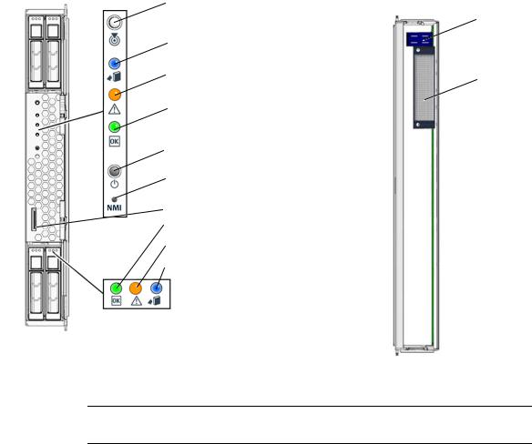
FIGURE 1-2 Front and Rear Panels |
|
|
Front View |
White - Locator LED |
Rear View |
|
||
|
(press to reset the LED) |
Power |
|
|
|
|
Blue - Ready to Remove LED |
connector |
|
|
|
|
Amber - Service Action Required LED |
Signal |
|
|
connector |
|
Green - OK LED |
|
|
Power button |
|
|
NMI (non-maskable interrupt, for |
|
|
service use only) |
|
|
Universal Connector Port (UCP) |
|
|
Green - Drive OK LED |
|
|
Amber - Drive Service Action Required LED |
|
|
Blue - Drive Ready to Remove LED |
|
Note – For information about connecting to the server module refer to the Sun Blade T6320 Server Module Installation Guide, 820-2384.
Chapter 1 Sun Blade T6320 Server Module Product Description 1-3
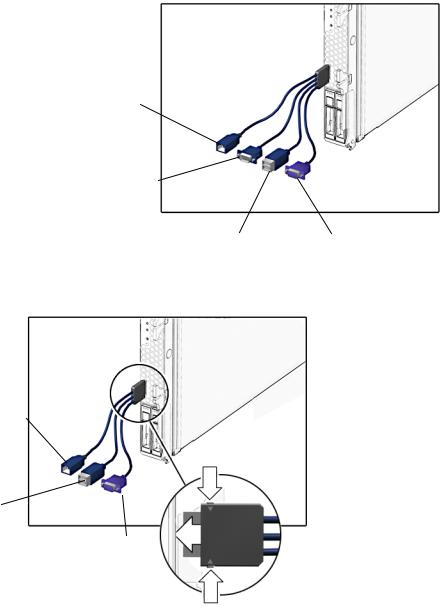
FIGURE 1-3 Cable Dongle Connectors
Four connector dongle cable (UCP-4)
RJ-45 (Do not use this connector with the Sun Blade T6320 Server Module)
DB-9 serial, male (TTYA)
USB 2.0 |
VGA 15-pin, female |
|
(two connectors) |
||
|
Three connector dongle cable (UCP-3)
RJ-45 serial
USB 2.0
(two connectors)
VGA 15-pin, female
Insert the connector straight into the server module.
1-4 Sun Blade T6320 Server Module Service Manual • June 2009
|
|
|
Caution – Insert the connector straight into the server module. The cable dongle is |
|
|
|
|
for temporary connections only. The cable dongle has not been evaluated for |
|
|
|
|
electromagnetic compatibility (EMC). The cable dongle or server module connectors |
|
|
|
|
could be damaged by closing rack doors or other impacts. Remove the cable dongle |
|
|
|
|
during normal system operation. |
|
|
|
|
|
|
|
|
|
|
|
|
|
|
Note – If you are using the older 4-cable dongle (UCP-4), do not use the RJ-45 |
|
|
|
|
connector with the Sun Blade T6320 server module. Use the DB-9 connector for serial |
|
|
|
|
connections. |
|
|
|
|
|
|
|
|
|
TABLE 1-1 Sun Blade T6320 Server Module Features |
|
|
|
|
|
|
Feature |
Description |
|||
|
|
|
|
|
Processor |
One UltraSPARC® T2 multicore processor with 4MB L2 cache. Can execute up to 64 |
|||
|
|
|
threads. |
|
Memory |
16 slots for fully buffered DIMMs (FB-DIMM), 667 MHz: |
|||
|
|
|
• 1 Gbyte (16 Gbyte maximum) |
|
|
|
|
• 2 Gbyte (32 Gbyte maximum) |
|
|
|
|
• 4 Gbyte (64 Gbyte maximum) |
|
Internal hard drives Up to four hot-pluggable 2.5-inch hard drives.
•SFF SAS 73 Gbyte, 15k rpm, and 10k rpm
•SFF SAS 146 Gbyte, 10k rpm
(Filler panels are inserted anywhere hard drives are not installed.)
RAID Expansion
Modules
RAID expansion modules (hard drive management) with RAID 0, 1 controller.
Eight links, x2 SAS (3 Gb/s) or SATA (1.5 Gb/s), supporting four internal hard drives and four x2 links to midplane. See Section 1.2, “Support for RAID Storage Configurations” on page 1-10.
Chapter 1 Sun Blade T6320 Server Module Product Description 1-5
TABLE 1-1 Sun Blade T6320 Server Module Features (Continued) |
|
|
|
Feature |
Description |
|
|
Universal |
One universal connector port (UCP) in the front panel. A universal cable is included with |
Connector Port |
the chassis and can be purchased separately (FIGURE 1-3). The following connections are |
|
supported: |
|
• USB 2.0* |
|
• VGA video |
|
• Serial (FIGURE 1-3). |
|
• Local keyboard, video, mouse, storage support (KVMS) |
Architecture |
SPARC® V9 architecture, ECC protected |
|
Platform group: sun4v |
|
Platform name: SUNW, Sun Blade T6320 Server Module |
|
Minimum system firmware 7.0.6 or subsequent compatible release |
|
Solaris 10 8/07 OS with appropriate patches |
XVR-50 on-board |
• 2D 24-bit color graphics |
graphics accelerator |
• Flexible 8- and 24-bit color application support |
|
• HD15 monitor connector for a wide range of Sun monitors |
|
• 3D support through Sun OpenGL® for SolarisTM software |
Some USB connectors are thick and may distort or damage the connector when you try to connect two USB cables. You can use a USB hub to avoid this problem.
|
TABLE 1-2 Interfaces With the chassis |
|
|
Feature |
Description |
|
|
Ethernet ports |
Two 10 Gb ethernet ports. Consult the chassis documentation or Network Express |
|
Module (NEM) documentation for ethernet pass-through specifications. (See FIGURE 1-5 |
|
and FIGURE A-2.) |
PCI Express I/O |
Two 8-lane ports connect to chassis midplane. Can support up to two 8-lane PCI |
|
ExpressModules (PCI EM). (FIGURE 1-5) |
SAS/SATA |
Four channels for remote storage connect from the RAID Express Module (REM) to the |
|
chassis midplane. |
Remote |
ILOM management controller on the service processor. CLI management (ssh only) and |
Management |
N1 system manager support. DMTF CLI and ALOM-CMT compatible CLI available |
|
through ssh. Remote console (remote KVMS) is configurable through OpenBoot PROM |
|
and ILOM. |
Remote |
ILOM management controller on the service processor. CLI management (telnet, ssh) and |
management |
N1 system manager support. ALOM CMT shell within the ILOM controller. |
Power |
Power is provided in the chassis |
Cooling |
Environmental controls are provided by the chassis. |
|
|
1-6 Sun Blade T6320 Server Module Service Manual • June 2009
For more information about chassis features and controls, refer to the service manual for your blade chassis at: http://docs.sun.com/app/docs/prod/blade.srvr
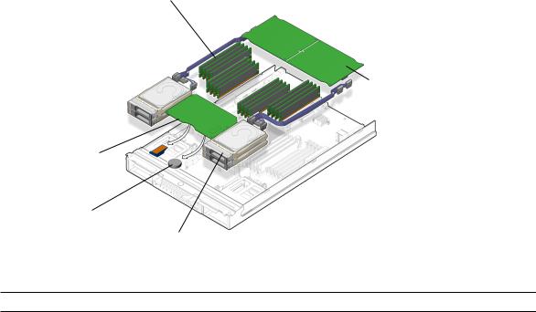
FIGURE 1-4 Field-Replaceable Units
FB-DIMMs
RAID Expansion Module
Service processor
with NVRAM (EEPROM) with ILOM and ALOM
Battery
Hard drives
TABLE 1-3 Sun Blade T6320 Server Module FRU List
FRU Description FRU Name* Replacement Instructions
Service |
Controls the host power and monitors host |
SYS/SP |
processor |
system events (power and environmental). |
|
card |
Socketed EEPROM stores system configuration, |
|
|
all Ethernet MAC addresses, and the host ID. |
|
Section 4.4, “Removing and Replacing the Service Processor” on page 4-15
Service |
Lithium battery |
SYS/SP/BAT |
Section 4.5, “Removing and |
processor |
|
|
Replacing the Battery on |
battery |
|
|
the Service Processor” on |
|
|
|
page 4-18 |
REMs |
RAID expansion modules (Hard drive |
SYS/MB/REM |
Section 4.6, “Replacing or |
|
management for up to 12 hard drives) |
|
Installing the Sun Blade |
|
|
|
RAID 5 Expansion Module” |
|
|
|
on page 4-20 |
|
|
|
Section 4.6, “Replacing or |
|
|
|
Installing the Sun Blade |
|
|
|
RAID 5 Expansion Module” |
|
|
|
on page 4-20 |
|
|
|
|
Chapter 1 Sun Blade T6320 Server Module Product Description 1-7
TABLE 1-3 |
Sun Blade T6320 Server Module FRU List (Continued) |
|
|
|
|
|
|
FRU |
Description |
FRU Name* |
Replacement Instructions |
FB-DIMMs |
1 Gbyte, 2 Gbyte, 4 Gbyte |
SYS/MB/CMPx/B |
Section 4.3.1, “Removing |
|
|
Rx/CHx/Dx |
the DIMMs” on page 4-10 |
Hard drive |
SFF SAS, or SATA 2.5-inch hard drive in NEMO |
HDD0,1,2,3 |
Section 3.2.2, “Removing a |
|
bracket |
|
Hard Drive” on page 3-2 |
Server |
Enclosure with CPU, motherboard |
SYS/MB |
New server module |
Module |
|
|
|
|
|
|
|
* The FRU name is used in system messages.
1-8 Sun Blade T6320 Server Module Service Manual • June 2009

FIGURE 1-5 PCI Express and Ethernet Connections on a Sun Blade 6000 Modular System
BL = blade (server module)
NEM1
NEM0
1.1.1Multicore Processor Information
The UltraSPARC® T2 multicore processor is the basis of the Sun Blade T6320 server module. The processor has four, six, or eight UltraSPARC cores. Each core equates to a 64-bit execution pipeline capable of running eight threads. The result is that the
Chapter 1 Sun Blade T6320 Server Module Product Description 1-9

8-core processor handles up to 64 active threads concurrently. For more information about the UltraSPARC® T2 multicore processor, go to: http://www.sun.com/processors/UltraSPARC-T2/features.xml http://www.sun.com/servers/wp.jsp?tab=1
1.2Support for RAID Storage Configurations
In addition to software RAID configurations, you can set up hardware RAID 1 (mirroring) and hardware RAID 0 (striping) configurations for any pair of internal hard drives using the on-board controller, providing a high-performance solution for hard drive mirroring.
By attaching one or more external storage devices (such as the Sun Blade 6000 Disk Module) to the Sun Blade T6320 server module, you can use a RAID to configure system drive storage in a variety of different RAID levels.
As shipped, the internal hard drives are not configured for RAID. To make a disk part of a RAID array while preserving the data on the drive, add the drive to a mirrored RAID set (also known as hardware RAID Level 1).
Before configuring RAID, you must configure a RAID expansion module (REM).The Sun Blade T6340 Server Module supports two REMs, the Sun Blade RAID 5 and Sun Blade RAID 0/1 G2 Expansion Modules.
Refer to the following for RAID configuration instructions:
■Uniform Command-Line Interface User's Guide, 820-2145
■Sun StorageTek RAID Manager Software User's Guide, 820-1177
■Sun StorageTek SAS RAID HBA Installation Guide Eight-Port, Internal HBA http://docs.sun.com/app/docs/doc/820-1847-17
■Sun Blade 6000 Disk Module Administration Guide, 820-4922 http://docs.sun.com/app/docs/prod/blade.6000disk~blade6000dskmod
Note – The Sun Blade 6000 Disk Module is an external storage blade that provides eight additional drives for configuring RAID and is supported for both REMs.
1-10 Sun Blade T6320 Server Module Service Manual • June 2009

1.2.1Sun Blade RAID 5 Expansion Module
The Sun Blade RAID 5 Expansion Module supports RAID levels 0, 1, 1E, 10, 5, or 6 with global or dedicated hot spares. When a Sun Blade RAID 5 Expansion Module is installed, SAS drives can be installed in disk slots 0 through 3. You can configure these disks as RAID 0, 1, 5, or 10.
For information on creating a bootable array, see Appendix B. For information on installing the OS on a bootable array, see Appendix C.
1.2.2Sun Blade RAID 0/1 G2 Expansion Module
The Sun Blade RAID 0/1 G2 Expansion Module supports RAID 1 (two mirrored disks with an optional hot spare) or RAID 1E (three or more mirrored disks with one or two hot spares).
1.3Finding the Serial Number
To obtain support for your system, you need the serial number. The serial number is located on a sticker on the front of the server module (FIGURE 1-6).
Chapter 1 Sun Blade T6320 Server Module Product Description 1-11
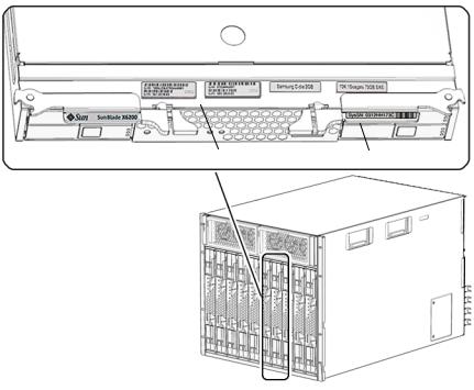
FIGURE 1-6 Serial Number and MAC Address Location
MAC address |
Serial number |
You can type the ILOM show /SYS command or the ALOM CMT showplatform command to obtain the chassis serial number. Both examples are shown below.
1-12 Sun Blade T6320 Server Module Service Manual • June 2009

-> show /SYS
/SYS
Targets: SERVICE LOCATE ACT OK2RM SP
MB MIDPLANE HDD0 HDD1 HDD2 HDD3 NEM0 NEM1
FM0... .... .... ...
Properties:
type = Host System keyswitch_state = Normal
chassis_name = SUN BLADE 6000 MODULAR SYSTEM chassis_part_number = 123-4567-89 chassis_serial_number = 0000000-0000YB005A chassis_manufacturer = SUN MICROSYSTEMS product_name = Sun Blade T6320 Server Module product_part_number = 541-2517-04 product_serial_number = 1005LCB-07385R001H product_manufacturer = SUN MICROSYSTEMS fault_state = OK
clear_fault_action = (none) prepare_to_remove_status = NotReady prepare_to_remove_action = (none) return_to_service_action = (none) power_state = On
ALOM CMT example:
Chapter 1 Sun Blade T6320 Server Module Product Description 1-13
sc> showplatform
SUNW, Sun Blade T6320 Server Module Blade Serial Number: 1005LCB-07385N005L Chassis Serial Number: 1005LCB-0709YM007M
Slot Number: 5 Domain Status
------ |
------ |
S0 |
Running |
sc> |
|
1.4Additional Service Related Information
Documentation for the Sun Blade T6320 server module, and related hardware and software is listed in “Accessing Sun Documentation” on page x.
The following resources are also available.
■SunSolvesm Online – Provides a collection of support resources. Depending on the level of your service contract, you have access to Sun patches, the Sun System Handbook, the SunSolve knowledge base, the Sun Support Forum, and additional documents, bulletins, and related links. Access this site at: http://www.sunsolve.sun.com/handbook_pub/
■Predictive Self-Healing Knowledge Database – You can access the knowledge article corresponding to a self-healing message by taking the Sun Message Identifier (SUNW-MSG-ID) and typing it into the field on this page: http://www.sun.com/msg/
1-14 Sun Blade T6320 Server Module Service Manual • June 2009

CHAPTER 2
Sun Blade T6320 Server Module
Diagnostics
This chapter describes the diagnostics that are available for monitoring and troubleshooting the Sun Blade T6320 server module.
This chapter is intended for technicians, service personnel, and system administrators who service and repair computer systems.
The following topics are covered:
■Section 2.1, “Sun Blade T6320 Server Module Diagnostics Overview” on page 2-2
■Section 2.2, “Memory Configuration and Fault Handling” on page 2-7
■Section 2.3, “Interpreting System LEDs” on page 2-12
■Section 2.4, “Using ILOM for Diagnosis and Repair Verification” on page 2-16
■Section 2.5, “Using the ILOM Web Interface For Diagnostics” on page 2-18
■Section 2.6, “Running POST” on page 2-31
■Section 2.7, “Using the Solaris Predictive Self-Healing Feature” on page 2-42
■Section 2.8, “Collecting Information From Solaris OS Files and Commands” on page 2-47
■Section 2.9, “Managing Components With Automatic System Recovery Commands” on page 2-48
■Section 2.10, “Exercising the System With SunVTS” on page 2-51
2-1

2.1Sun Blade T6320 Server Module Diagnostics Overview
There are a variety of diagnostic tools, commands, and indicators you can use to monitor and troubleshoot a Sun Blade T6320 server module.
■LEDs – Provide a quick visual notification of the status of the server module and some of the FRUs.
■ILOM firmware – This system firmware runs on the service processor. In addition to providing the interface between the hardware and the Solaris OS, ILOM tracks and reports the health of key server module components. ILOM works closely with POST and Solaris Predictive Self-Healing technology to keep the system up and running even when there is a faulty component. For more information about ILOM, see these documents:
■Sun Integrated Lights out Manager 2.0 User’s Guide, 820-1188
■Sun Integrated Lights Out Manager 2.0 Supplement for Sun Blade T6320 Server Modules, 820-2546. This document describes ILOM information specific to the UltraSPARC and the Sun Blade T6320 server module. It also provides command comparisons of the ALOM CMT and ILOM CLI command sets.
■Appendix D of this service manual provides some information about using the ALOM CMT CLI.
■Power-on self-test (POST) – POST performs diagnostics on system components upon system reset to ensure the integrity of those components. POST is configurable and works with ILOM to take faulty components offline if needed.
■Solaris OS Predictive Self-Healing (PSH) – This technology continuously monitors the health of the CPU and memory, and other components. PSH works with ILOM to take a faulty component offline if needed. The Predictive SelfHealing technology enables Sun systems to accurately predict component failures and mitigate many serious problems before they occur.
■Log files and console messages – Provide the standard Solaris OS log files and investigative commands that can be accessed and displayed on the device of your choice.
■SunVTS™ – An application that exercises the system, provides hardware validation, identifies possible faulty components, and provides recommendations for repair.
The LEDs, ILOM, Solaris OS PSH, and many of the log files and console messages are integrated. For example, when the Solaris software detects a fault, it will display the fault, log it, pass information to ILOM where the fault is logged, and depending on the fault, one or more LEDs may be illuminated.
2-2 Sun Blade T6320 Server Module Service Manual • June 2009
The diagnostic flowchart in FIGURE 2-1 and TABLE 2-1 describes an approach for using the server module diagnostics to identify a faulty field-replaceable unit (FRU). The diagnostics you use, and the order in which you use them, depend on the nature of the problem you are troubleshooting, so you might perform some actions and not others.
Use this flowchart to understand what diagnostics are available to troubleshoot faulty hardware, and use to find more information about each diagnostic in this chapter.
Chapter 2 Sun Blade T6320 Server Module Diagnostics 2-3
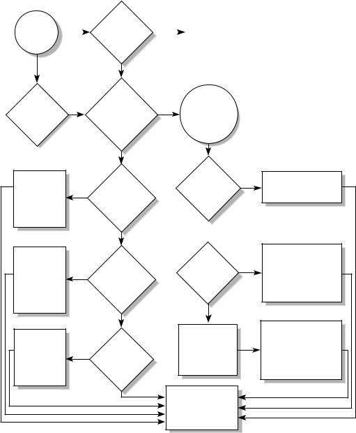
FIGURE 2-1 Diagnostic Flowchart
Faulty |
|
1. Are the |
|
|
|
Check the |
|
|
|
|
|
|
|||
|
|
|
|
power source |
|
||
hardware |
|
Power OK |
|
|
|
|
|
|
|
|
|
and |
|
||
|
Yes |
|
|
||||
suspected |
|
LEDs |
|
|
|||
|
|
connections. |
|
||||
|
|
off? |
|
|
|
|
|
|
|
|
|
|
|
|
|
|
|
|
|
|
|
|
|
|
|
|
|
|
|
|
|
Numbers in this flow chart correspond to the Action numbers in Table 2-1.
|
|
No |
|
|
|
|
Are any |
|
2. Are any |
|
The ILOM |
|
|
|
|
show/SP/ |
|
|
||
|
faults reported |
|
|
|
||
Service |
|
|
faultmgt |
|
|
|
|
by the ILOM show |
|
|
|
||
LEDs |
|
Yes |
command displays |
|
|
|
|
/SP/faultmgt |
|
|
|||
0n? |
|
a fault |
|
|
||
|
command? |
|
|
|
||
|
|
|
|
|
|
|
|
|
No |
|
|
|
|
Identify faulty |
|
|
|
6. Is |
|
Identify the fault condition |
|
3. Do |
|
the fault an |
|
||
FRU from the |
|
the Solaris logs |
|
environmental |
Yes |
from the fault message. |
fault message |
Yes |
indicate a faulty |
|
fault? |
|
|
and replace |
|
|
|
|||
|
FRU? |
|
|
|
|
|
the FRU. |
|
|
|
|
|
|
|
|
|
No |
|
|
|
|
|
|
|
|
|
|
|
|
No |
|
|
|
|
Identify faulty |
|
|
|
7. Is the |
|
Identify and replace the |
|
4. Does |
|
|
faulty FRU from the PSH |
||
FRU from the |
|
|
fault a PSH |
|
||
|
|
|
message and perform the |
|||
Sun VTS |
|
Sun VTS report |
|
detected |
Yes |
|
|
|
procedure to clear the |
||||
message and |
Yes |
any faulty |
|
fault? |
||
|
|
PSH detected fault. |
||||
replace the |
|
devices? |
|
|
|
|
|
|
|
|
|
||
FRU. |
|
No |
|
No |
|
|
|
|
|
|
|
|
|
|
|
|
|
|
|
Identify and replace the |
Identify faulty |
|
5. Does |
|
8. The fault |
|
faulty FRU from the POST |
FRU from the |
|
|
is a POST |
|
message and perform the |
|
|
POST report |
|
|
|||
POST message |
|
|
detected fault. |
|
procedure to clear the |
|
Yes |
any faulty |
|
|
|||
and replace |
|
|
|
POST detected faults. |
||
devices? |
|
|
|
|||
the FRU. |
|
|
|
|
|
|
|
|
|
|
|
|
|
|
|
No |
|
9. Contact Sun |
|
|
|
|
|
|
|
|
|
|
|
|
|
Support if the fault |
|
|
|
|
|
|
condition persists. |
|
|
2-4 Sun Blade T6320 Server Module Service Manual • June 2009
Loading...