


 Loading...
Sun Fire™ V120 and Netra™ 120
Server User’s Guide
Sun Microsystems, Inc.
901 San Antonio Road
Palo Alto, CA 94303
U.S.A. 650-960-1300
Part No. 816-2090-10
December 2001, Revision A
Send comments about this document to: docfeedback@sun.com
Copyright 2001 Sun Microsystems, Inc., 901 San Antonio Road, Palo Alto, CA 94303-4900 U.S.A. All rights reserved.
This product or document is distributed under licenses restricting its use, copying, distribution, and decompilation. No part of this product or document may be reproduced in any form by any means without prior written authorization of Sun and its licensors, if any. Third-party software, including font technology, is copyrighted and licensed from Sun suppliers.
Parts of the product may be derived from Berkeley BSD systems, licensed from the University of California. UNIX is a registered trademark in the U.S. and other countries, exclusively licensed through X/Open Company, Ltd.
Sun, Sun Microsystems, the Sun logo, AnswerBook2, docs.sun.com, Solaris, Sun Enterprise, OpenBoot, SunSolve, Sun Fire and Netra are trademarks, registered trademarks, or service marks of Sun Microsystems, Inc. in the U.S. and other countries. All SPARC trademarks are used under license and are trademarks or registered trademarks of SPARC International, Inc. in the U.S. and other countries. Products bearing SPARC trademarks are based upon an architecture developed by Sun Microsystems, Inc.
The OPEN LOOK and Sun™ Graphical User Interface was developed by Sun Microsystems, Inc. for its users and licensees. Sun acknowledges the pioneering efforts of Xerox in researching and developing the concept of visual or graphical user interfaces for the computer industry. Sun holds a non-exclusive license from Xerox to the Xerox Graphical User Interface, which license also covers Sun’s licensees who implement OPEN LOOK GUIs and otherwise comply with Sun’s written license agreements.
Federal Acquisitions: Commercial Software—Government Users Subject to Standard License Terms and Conditions.
DOCUMENTATION IS PROVIDED “AS IS” AND ALL EXPRESS OR IMPLIED CONDITIONS, REPRESENTATIONS AND WARRANTIES, INCLUDING ANY IMPLIED WARRANTY OF MERCHANTABILITY, FITNESS FOR A PARTICULAR PURPOSE OR NON-INFRINGEMENT, ARE DISCLAIMED, EXCEPT TO THE EXTENT THAT SUCH DISCLAIMERS ARE HELD TO BE LEGALLY INVALID.
Copyright 2001 Sun Microsystems, Inc., 901 San Antonio Road, Palo Alto, CA 94303-4900 Etats-Unis. Tous droits réservés.
Ce produit ou document est distribué avec des licences qui en restreignent l’utilisation, la copie, la distribution, et la décompilation. Aucune partie de ce produit ou document ne peut être reproduite sous aucune forme, par quelque moyen que ce soit, sans l’autorisation préalable et écrite de Sun et de ses bailleurs de licence, s’il y en a. Le logiciel détenu par des tiers, et qui comprend la technologie relative aux polices de caractères, est protégé par un copyright et licencié par des fournisseurs de Sun.
Des parties de ce produit pourront être dérivées des systèmes Berkeley BSD licenciés par l’Université de Californie. UNIX est une marque déposée aux Etats-Unis et dans d’autres pays et licenciée exclusivement par X/Open Company, Ltd.
Sun, Sun Microsystems, le logo Sun, AnswerBook2, docs.sun.com, Solaris, Sun Enterprise, OpenBoot, SunSolve, Sun Fire et Netra sont des marques de fabrique ou des marques déposées, ou marques de service, de Sun Microsystems, Inc. aux Etats-Unis et dans d’autres pays. Toutes les marques SPARC sont utilisées sous licence et sont des marques de fabrique ou des marques déposées de SPARC International, Inc. aux EtatsUnis et dans d’autres pays. Les produits portant les marques SPARC sont basés sur une architecture développée par Sun Microsystems, Inc.
L’interface d’utilisation graphique OPEN LOOK et Sun™ a été développée par Sun Microsystems, Inc. pour ses utilisateurs et licenciés. Sun reconnaît les efforts de pionniers de Xerox pour la recherche et le développement du concept des interfaces d’utilisation visuelle ou graphique pour l’industrie de l’informatique. Sun détient une licence non exclusive de Xerox sur l’interface d’utilisation graphique Xerox, cette licence couvrant également les licenciés de Sun qui mettent en place l’interface d’utilisation graphique OPEN LOOK et qui en outre se conforment aux licences écrites de Sun.
LA DOCUMENTATION EST FOURNIE “EN L’ETAT” ET TOUTES AUTRES CONDITIONS, DECLARATIONS ET GARANTIES EXPRESSES OU TACITES SONT FORMELLEMENT EXCLUES, DANS LA MESURE AUTORISEE PAR LA LOI APPLICABLE, Y COMPRIS NOTAMMENT TOUTE GARANTIE IMPLICITE RELATIVE A LA QUALITE MARCHANDE, A L’APTITUDE A UNE UTILISATION PARTICULIERE OU A L’ABSENCE DE CONTREFAÇON.
Please
Recycle

Contents
Part I Installation and Configuration
1.Introduction 1-1
1.1 |
Overview of the Sun Fire V120 and Netra 120 Servers 1-2 |
1.2 |
Contents of the Ship Kit 1-3 |
1.3 |
Optional Hardware and Software 1-5 |
1.4Front Panel 1-6
1.5Back Panel 1-7
1.6 |
The Fans Inside the Sun Fire V120 and Netra 120 Servers 1-8 |
1.7 |
Tools You Need for Installation 1-8 |
1.8Environmental Specifications 1-9
|
1.8.1 Tolerance of Environmental Conditions |
1-9 |
|
1.8.2 Acoustic Noise Generated by the Server |
1-9 |
|
1.8.3 Environmental Compliance Information |
1-9 |
1.9 |
Choosing Between a Rack and a Cabinet 1-10 |
|
2. Power and Cooling 2-1 |
|
|
2.1 |
Operating Power Limits and Ranges 2-2 |
|
2.2Power Consumption 2-3
2.3 |
Estimating Heat Dissipation 2-4 |
Contents iii
3. Using DC Power 3-1
3.1 |
Grounding the Netra 120 Server 3-2 |
|
3.2 |
Assembling the DC Power Connectors 3-3 |
|
|
3.2.1 |
The Insulated Conductors You Need to Use 3-3 |
|
3.2.2 |
Assembling the DC Input Power Cable 3-3 |
|
3.2.3 |
Installing the Strain Relief Housings 3-7 |
4. Installing Optional Hardware Components 4-1
4.1 |
Installing and Removing Hot-Pluggable SCSI Hard Disk Drives 4-2 |
4.2 |
Opening the Server 4-4 |
4.3 |
Identifying Server Components 4-6 |
4.4Installing and Removing a DVD or
|
CD-ROM Drive 4-7 |
|
|
|
|
4.4.1 |
Installing a DVD or CD-ROM Drive |
4-7 |
|
|
4.4.2 |
Removing a DVD or CD-ROM Drive |
4-9 |
|
4.5 |
Installing and Removing Memory 4-9 |
|
||
4.6 |
Installing and Removing a PCI Card 4-11 |
|
||
|
4.6.1 |
Installing a PCI Card |
4-11 |
|
|
4.6.2 |
Removing a PCI Card |
4-14 |
|
4.7 |
Replacing the Server’s Top Cover 4-14 |
|
|
|
5. Installing the Server Into a Rack 5-1 |
|
|
||
5.1 |
Installing Into a 19-Inch Four-Post Rack |
5-2 |
|
|
|
5.1.1 |
The 19-Inch Rackmounting Kit |
5-2 |
|
|
5.1.2 |
Assembling the Slides and Mounting the Server 5-3 |
||
|
5.1.3 |
Fitting the Cable Management Bracket |
5-10 |
|
|
5.1.4 |
Tips for Using a Sun StorEdge 72-inch Rack 5-11 |
||
5.2 |
Installing Into a Two-Post Relay Rack 5-12 |
|
||
|
5.2.1 |
The Fixed Mounting Bracket Kit |
5-12 |
|
|
5.2.2 |
Attaching the Fixed-Mounting Brackets |
5-12 |
|
iv Sun Fire V120 and Netra 120 Server User’s Guide • December 2001
6. Connecting the Cables 6-1 |
|
|
|
||
6.1 |
Connecting the Cables to the Server 6-2 |
|
|
||
6.2 |
Using a Single DC Power Cord |
6-4 |
|
|
|
6.3 |
Setting Up Serial Connections |
6-4 |
|
|
|
|
6.3.1 |
Connecting to a Terminal Server |
6-5 |
|
|
|
6.3.2 |
Using a DB-25 Adapter for Your Serial Link |
6-7 |
||
|
6.3.3 |
Using a DB-9 Adapter for Your Serial Link |
6-8 |
||
|
6.3.4 |
Settings for the Serial Connections |
6-9 |
|
|
6.4Connecting to Your Server From a Laptop Running Microsoft Windows 6-10
6.4.1Connecting the Sun Fire V120 or Netra 120 Server to the Laptop 6-10
|
6.4.2 |
Using Microsoft Windows HyperTerminal 6-11 |
|
7. Powering On the Sun Fire V120 or Netra 120 Server 7-1 |
|||
7.1 |
Preparing to Configure the Server |
7-2 |
|
|
7.1.1 |
Using a Terminal Server |
7-2 |
|
7.1.2 |
Configuring From a Terminal or Workstation 7-2 |
|
7.2 |
Powering On the Server 7-3 |
|
|
7.2.1Powering On for the First Time With the Server’s Details Registered
at a Name Server 7-3
7.2.2Powering On the Server for the First Time Without Having Its Details Registered 7-4
|
|
7.2.3 Powering On a Standalone Server for the First Time 7-5 |
||
|
|
7.2.4 Clearing Your Configuration and Starting Again |
7-6 |
|
|
7.3 |
Using the Power (On/Standby) Switch |
7-7 |
|
Part II |
Remote and Local Management |
|
|
|
8. |
Managing the Server From the lom> Prompt |
8-1 |
|
|
|
8.1 |
Introduction to Lights-Out Management |
8-2 |
|
|
8.2 |
Powering On or Resetting the Server From the LOM Shell |
8-3 |
|
Contents v
8.2.1 |
Powering the Server On or Down to Standby Mode |
8-4 |
||||||
8.2.2 |
Displaying the lom> Prompt |
8-4 |
|
|
|
|
|
|
8.2.3 |
Exiting From the lom> Prompt |
8-5 |
|
|
|
|
|
|
8.2.4 |
Resetting the Server 8-5 |
|
|
|
|
|
|
|
8.2.5 |
Displaying the ok or kadb Prompt |
8-6 |
|
|
|
|||
8.2.6 |
Controlling the Server’s Booting Behavior |
8-6 |
|
|||||
8.3 Monitoring the Server From the LOM Shell |
8-8 |
|
|
|
||||
8.3.1 |
Checking How Long the Server Has Been Running |
8-8 |
||||||
8.3.2 |
Checking the Current Status of All Components 8-8 |
|||||||
8.3.3 |
Viewing the LOM Device’s Event Log |
8-10 |
|
|
||||
8.3.4 |
Checking That a Component Has Been Fixed |
8-12 |
|
|||||
8.4 Setting Up LOM Privileges for Named Users |
|
8-13 |
|
|
||||
8.4.1 |
Permission Levels Available for LOM Users |
8-13 |
|
|||||
8.4.2 |
Creating a LOM User Account |
8-14 |
|
|
|
|
|
|
8.4.3 |
Specifying the Password for a LOM User Account |
8-14 |
||||||
8.4.4 |
Viewing Details of a LOM User Account |
8-15 |
|
|||||
8.4.5 |
Changing Your Own User Password |
|
8-15 |
|
|
|||
8.4.6 |
Deleting a LOM User Account |
8-15 |
|
|
|
|
|
|
8.4.7 |
Specifying Permissions for a Named User |
8-16 |
|
|||||
8.4.8 |
Quitting a LOM Named User Session |
8-17 |
|
|
||||
8.5 Setting the LOM Device’s Configurable Variables |
8-17 |
|
||||||
8.5.1 |
Turning the Fault LED on |
8-17 |
|
|
|
|
|
|
8.5.2 |
Turning the Fault LED off |
8-17 |
|
|
|
|
|
|
8.5.3 |
Setting the alarmon n Software Flag |
|
8-18 |
|
|
|||
8.5.4 |
Setting the alarmoff n Software Flag 8-18 |
|
|
|||||
8.5.5Stopping the LOM Sending Event Reports to the Serial A/LOM port 8-18
8.6 Separating the LOM From the Console on the Serial A/LOM Port |
8-19 |
|
8.6.1 |
Dedicating Serial A/LOM to the LOM 8-19 |
|
8.6.2 |
Sharing Serial A/LOM Between the LOM and the Console |
8-20 |
vi Sun Fire V120 and Netra 120 Server User’s Guide • December 2001
8.7 |
Viewing the Event Reports That the LOM Sends to syslogd 8-20 |
|||
8.8 |
The LOM Shell Command List 8-21 |
|
|
|
8.9 |
Checking the Status of the Server’s Fans |
8-23 |
||
9. Managing the Server From the Solaris Prompt |
9-1 |
|||
9.1 |
Monitoring the System From Solaris |
9-2 |
|
|
|
9.1.1 |
Viewing Online LOM Documentation 9-2 |
||
|
9.1.2 |
Checking the Power Supply Unit (lom -p) 9-2 |
||
|
9.1.3 |
Checking the Fans (lom -f) |
9-3 |
|
9.1.4Checking the Supply Rail Voltages and Internal Circuit Breakers (lom -v) 9-3
9.1.5 |
Checking the Internal Temperature (lom -t) 9-4 |
9.1.6 |
Checking the Status of the Fault LED and Alarms (lom -l) 9-5 |
9.1.7Changing the LOM Automatic Server Restart Configuration (lom -w) 9-5
9.1.8 Viewing the Configuration of the LOM Device (lom -c) 9-6
9.1.9Viewing All Component Status Data With the LOM Device’s Configuration Data (lom -a) 9-6
9.1.10 Viewing the Event Log (lom -e) 9-7
9.2 Configuring Automatic Server Restart (ASR) 9-8
9.2.1Configuring the LOM Watchdog to Restart the System After a Lockup 9-8
9.2.2Enabling the LOM Watchdog Process From Your Own Script or Command (lom -W on) 9-9
9.2.3Setting the Hardware Reset Option From a Script or Command (lom -R on) 9-10
9.3 Other LOM Tasks You Can Perform From Solaris 9-11
9.3.1 |
Turning Alarms On and Off (lom -A) 9-11 |
9.3.2 |
Turning the Fault LED On and Off (lom -F) 9-11 |
9.3.3Changing the First Character of the Sequence for Escaping to the lom> Prompt (lom -X) 9-12
9.3.4Stopping the LOM from Sending Reports to the Serial A/LOM Port (lom -E off) 9-12
Contents vii
9.3.5 Making the LOM Interface Backward Compatible (lom -B) 9-13
9.3.6Upgrading the LOM Firmware (lom -G filename) 9-13
Part III Troubleshooting and Maintenance
10.Troubleshooting 10-1
10.1 Introduction to the POST, obdiag, and SunVTS Diagnostic Tools 10-2
10.1.1 Using POST Diagnostics 10-2
10.1.2 Using OpenBoot Diagnostics (obdiag) 10-3
10.1.3Using SunVTS 10-5
10.2 Additional Diagnostic Tests for Specific Devices 10-8
10.2.1Using the probe-scsi Command To Confirm That Hard Disk
Drives Are Active 10-8
10.2.2Using the probe-ide Command To Confirm That the DVD or CD-
ROM Drive is Connected 10-9
10.2.3 Using the watch-net and watch-net-all Commands To Check
|
the Network Connections 10-9 |
|
10.3 |
Solutions to Problems You Might Encounter |
10-10 |
10.4 |
Interpreting the Front and Back Panel LEDs |
10-12 |
11. Replacing a Server or Replacing Individual Components 11-1
11.1 |
Replacing a Server 11-2 |
11.2 |
Field Replaceable Units 11-4 |
11.3Replacing the Memory Card Reader for the System Configuration Card 11-5
11.4 |
Replacing the DVD or CD-ROM Drive, Cable, and Paddleboard 11-7 |
||
11.5 |
Replacing the NVRAM Chip |
11-9 |
|
11.6 |
Replacing the System Board |
11-12 |
|
|
11.6.1 Removing the Old System Board |
11-12 |
|
|
11.6.2 Installing the New System Board |
11-15 |
|
11.7 |
Replacing the Power Supply Unit 11-17 |
|
|
11.8 |
Replacing the Rear Fan Subassembly (Fans 1 and 2) 11-19 |
||
viii Sun Fire V120 and Netra 120 Server User’s Guide • December 2001
|
11.9 |
Replacing Fan 3 11-21 |
|
|
Part IV |
Appendixes |
|
|
|
A. Installing and Removing a SCSI Hard Disk Drive with Solaris Running A-1 |
||||
|
A.1 |
Installing a SCSI Hard Disk Drive With Solaris Running |
A-2 |
|
|
A.2 |
Removing a SCSI Hard Disk Drive With Solaris Running |
A-4 |
|
12. |
Reinstalling the Solaris Operating Environment B-1 |
|
||
|
B.1 |
Reinstalling Solaris B-2 |
|
|
|
B.2 |
Reinstalling the Lights-Out Management Software B-2 |
|
|
B. Configuring the LOM Device Driver C-1 |
|
|||
|
C.1 |
The LOM Device Driver |
C-2 |
|
|
C.2 |
Configuring the LOM Device Driver C-3 |
|
|
C. System Board Jumper Settings |
D-1 |
|
||
|
Index |
1 |
|
|
Contents ix
x Sun Fire V120 and Netra 120 Server User’s Guide • December 2001
Figures
FIGURE 1-1
FIGURE 1-2
FIGURE 1-3
FIGURE 1-4
FIGURE 1-5
FIGURE 3-1
FIGURE 3-2
FIGURE 3-3
FIGURE 3-4
FIGURE 3-5
FIGURE 3-6
FIGURE 3-7
FIGURE 3-8
FIGURE 3-9
FIGURE 4-1
FIGURE 4-2
FIGURE 4-3
FIGURE 4-4
FIGURE 4-5
The Sun Fire V120 Server 1-2
Contents of the Ship Kit 1-4
The Front Panel of the Sun Fire V120 and Netra 120 Servers 1-6
The Back Panel of the Sun Fire V120 Server 1-7
The Back Panel of the Netra 120 Server 1-7
The Location of the Grounding Studs for Connecting the Two-Hole Lug 3-2
Stripping the Insulation From the Wire |
3-4 |
|
Opening the DC Connector Cage Clamp (Lever Method) |
3-5 |
|
Opening the DC Connector Cage Clamp (Screwdriver Method) 3-6 |
||
Assembling the DC Input Power Cable |
3-6 |
|
Inserting the Bottom Portion of the Strain Relief Housing |
3-7 |
|
Routing the Wires Out of the Strain Relief Housing 3-8 |
|
|
Securing the Wires to the Strain Relief Housing 3-8 |
|
|
Assembling the Strain Relief Housing |
3-9 |
|
Inserting and Removing Hard Disks 4-3 |
|
|
Using the Antistatic Wrist Strap Supplied With the Server |
4-4 |
|
Removing the Top Cover 4-5 |
|
|
Components of the Sun Fire V120 and Netra 120 Servers |
4-6 |
|
Installing an Internal DVD or CD-ROM Drive 4-8 |
|
|
xi
FIGURE 4-6
FIGURE 4-7
FIGURE 4-8
FIGURE 4-9
FIGURE 5-1
FIGURE 5-2
FIGURE 5-3
FIGURE 5-4
FIGURE 5-5
FIGURE 5-6
FIGURE 5-7
FIGURE 5-8
FIGURE 5-9
FIGURE 5-10
FIGURE 5-11
FIGURE 5-12
FIGURE 6-1
FIGURE 6-2
FIGURE 6-3
FIGURE 6-4
FIGURE 6-5
FIGURE 6-6
FIGURE 1
FIGURE 7-1
FIGURE 7-2
FIGURE 8-1
FIGURE 8-2
Installing Memory into a Socket on the System Board 4-10 |
|
|
The Rotating Retention Bracket and the Position of a PCI Card |
4-12 |
|
Using the PCI Card Retainer, Slide Support Rail, and Plastic Bracket |
4-13 |
|
Replacing the Top Cover 4-15 |
|
|
Cable Management Bracket 5-2 |
|
|
Positioning the Slide Mounts for a Sun StorEdge 72-Inch Tall Rack |
5-3 |
|
Positioning the Slide Mounts for a Standard 19-Inch Wide Rack |
5-3 |
|
Fastening the Slide Mounts to a Sun StorEdge 72-inch Tall Rack–Rear View (Side Panels Removed for Clarity) 5-5
Fastening the Slide Mounts to a Sun StorEdge 72-inch Expansion Rack–Front View (Side Panels Removed for Clarity) 5-6
Fastening the Slide Mounts to a Standard 19-inch Rack 5-7
Sliding the Server Into a Standard 19-Inch Rack 5-8
Adjusting the Slide Mounts and Screwing the Server Into the Rack 5-9
Fitting the Cable Management Bracket to a Sun StorEdge or a Standard 19-Inch Rack 5-10
Removing the Thumbscrew Brackets |
5-12 |
|
|
|
|
Fitting the Fixed Mounting Brackets |
5-13 |
|
|
|
|
The Server Installed in a Two-Post Rack 5-14 |
|
|
|
||
Connecting the Cables to the Sun Fire V120 Server |
6-2 |
|
|||
Connecting the Cables to the Netra 120 Server |
6-2 |
|
|
||
Patch Panel Connection Between a Terminal Server and a Sun Fire V120 |
6-5 |
||||
Pins 1 to 8 on the Serial Port |
6-6 |
|
|
|
|
Pins 1 to 8 on the Serial Ports |
6-7 |
|
|
|
|
Pins 1 to 8 on the Serial Ports |
6-8 |
|
|
|
|
Connecting the Server to the Serial Port on a Laptop |
6-10 |
|
|||
Netra 120 Server Power (On/Standby) Switch |
7-7 |
|
|
||
Sun Fire V120 Server Power (On/Standby) Switch 7-7 |
|
||||
The Location of the Lights-Out Management Device on the System Board |
8-2 |
||||
Sample Output From the environment Command |
8-9 |
|
|||
xii Sun Fire V120 and Netra 120 Server User’s Guide • December 2001
FIGURE 8-3
FIGURE 8-4
FIGURE 9-1
FIGURE 10-1
FIGURE 10-2
FIGURE 10-3
FIGURE 10-4
FIGURE 10-5
FIGURE 10-6
FIGURE 10-7
FIGURE 10-8
FIGURE 11-1
FIGURE 11-2
FIGURE 11-3
FIGURE 11-4
FIGURE 11-5
FIGURE 11-6
FIGURE 11-7
FIGURE 11-8
FIGURE 11-9
FIGURE 11-10
FIGURE 11-11
FIGURE D-1
Sample LOM Device Event Log (Oldest Event Reported First) |
8-10 |
||||
Locations of Fans 1, 2, 3, and 4 |
8-23 |
|
|
|
|
Sample LOM Device Event Log (Oldest Event Reported First) |
9-7 |
||||
Sample obdiag Menu 10-3 |
|
|
|
|
|
probe-scsi Output Message |
10-8 |
|
|
|
|
probe-scsi-all Output Message |
10-8 |
|
|
|
|
probe-ide Output Message |
10-9 |
|
|
|
|
watch-net Diagnostic Output Message |
10-10 |
|
|
||
watch-net-all Diagnostic Output Message 10-10 |
|
||||
Front Panel Power and Fault LEDs |
10-13 |
|
|
|
|
Back Panel Ethernet Link, Fault and Power LEDs |
10-13 |
|
|||
Replacing the System Configuration Card |
11-3 |
|
|
||
Removing the System Configuration Card Reader |
11-6 |
|
|||
Replacing the Paddleboard at the Back of the DVD or CD-ROM Drive Enclosure 11-8
The Location of the NVRAM Chip |
11-10 |
Replacing the NVRAM Chip 11-11 |
|
Unplugging and Removing the Fan 3 Assembly 11-13 |
|
The System Board 11-14 |
|
Replacing the Fan 3 Assembly 11-16 |
|
Replacing the Power Supply Unit |
11-18 |
Replacing the Rear Fan Subassembly (Fans 1 and 2) 11-20 |
|
Disconnecting the Power Cable for Fan 3 and Lifting the Fan Out 11-21
System Board Jumper Locations and Default Settings D-4
Figures xiii
xiv Sun Fire V120 and Netra 120 Server User’s Guide • December 2001

Tables
TABLE 1-1 |
Contents of the Ship Kit |
1-3 |
|
|
|
TABLE 1-2 |
Customer-Installable Hardware and Software |
1-5 |
|
||
TABLE 2-1 |
Operating Power Limits and Ranges for Sun Fire V120 and Netra 120 Servers 2-2 |
||||
TABLE 2-2 |
Power Consumption for the Available Configurations of the Server |
2-3 |
|||
TABLE 5-1 |
19-inch Rackmounting Kit |
5-2 |
|
|
|
TABLE 5-2 |
Fixed Mounting Bracket Kit |
5-12 |
|
|
|
TABLE 6-1 |
Serial Port Connection to a Terminal Server |
6-6 |
|
||
TABLE 6-2 |
Pin Inter-connections Performed by the Sun DB-25 (25-pin) Adapter |
6-7 |
|||
TABLE 6-3 |
Pin Inter-connections Required to be Performed by a DB-9 (9-pin) Adapter 6-8 |
||||
TABLE 6-4 |
Default Settings for Connecting to the Serial A/LOM or Serial B Port |
6-9 |
|||
TABLE 6-5 |
Pin Inter-connections Required to be Performed by the 25x9-way D-type Female-to-Female |
||||
|
Adapter 6-11 |
|
|
|
|
TABLE 8-1 |
Boot Modes 8-7 |
|
|
|
|
TABLE 8-2 |
LOM Commands 8-21 |
|
|
|
|
TABLE 10-1 |
Open Boot Diagnostics Tests |
10-4 |
|
|
|
TABLE 10-2 |
SunVTS Tests 10-5 |
|
|
|
|
TABLE 11-1 |
FRUs Available for the Sun Fire V120 and Netra 120 Servers 11-4 |
|
|||
TABLE C-1 |
LOM Configuration File Parameters C-3 |
|
|
||
TABLE D-1 |
Factory-Default Jumper Settings D-2 |
|
|
||
xv
xvi Sun Fire V120 and Netra 120 Server User’s Guide • December 2001

Preface
The Sun Fire V120 and Netra 120 Server User’s Guide describes how to install, manage, and maintain the Sun FireTM V120 and NetraTM 120 servers. The manual is intended for system administrators who have experience in setting up networked SolarisTM servers.
How This Book Is Organized
Part I Installation and Configuration
Chapter 1 introduces the Sun FireTM V120 and NetraTM 120 servers, lists the customer-installable hardware and software components available for them, and identifies the main features of the servers’ front and back panels.
Chapter 2 provides information about the power and cooling requirements for the Sun FireTM V120 and NetraTM 120 servers.
Chapter 3 describes how to assemble the DC input power cable.
Chapter 4 describes how to install optional (hot-pluggable) Hard Disk Drives and also how to open the server, identify its components, and install memory DIMMs, a PCI expansion card, or a DVD or CD-ROM drive.
Chapter 5 describes how to install the server into different types of racks.
Chapter 6 describes how to connect the cables and set up serial connections to the server.
Chapter 7 describes how to perform the initial power-on and configuration of the server.
xvii

Part II Remote and Local Management
Chapter 8 describes how to use the Lights-Out Management (LOM) shell to power the server on and off or reset it remotely. It also describes how to use this shell to view status information about the server’s fans, power supply, supply rails, operating temperature, and internal circuit breakers.
Chapter 9 describes how to use the LOM-specific Solaris commands to monitor and manage the system. This chapter also explains how to configure the LOM device to restart the server automatically after a system lockup.
Part III Troubleshooting and Maintenance
Chapter 10 lists some problems that you might encounter while setting up or using the server and tells you how to solve them. It also describes the server’s LEDs.
Chapter 11 lists the field-replaceable units (FRUs) that you can order for your server and tells you how to install them.
Part IV Appendixes
Appendix A tells you how to install and remove Hard Disk Drives from the server without shutting the operating system down.
Appendix B provides information on re-installing Solaris and the Lights-Out Management (LOM) software.
Appendix C describes the parameters you can configure in the LOM driver configuration file.
Appendix D provides the locations and the factory default settings of the jumpers on the system board.
Using Solaris Commands
This document does not contain information on basic Solaris commands and procedures such as shutting down the system, booting the system, and configuring devices.
See one or more of the following for this information:
■AnswerBook2™ online documentation for the Solaris operating environment
■Other software documentation that you received with your system
xviii Sun Fire V120 and Netra 120 Server User’s Guide • December 2001

Typographic Conventions
Typeface |
Meaning |
Examples |
|
|
|
AaBbCc123 |
The names of commands, files, |
Edit your .login file. |
|
and directories; on-screen |
Use ls -a to list all files. |
|
computer output |
% You have mail. |
AaBbCc123 |
What you type, when |
% su |
|
contrasted with on-screen |
Password: |
|
computer output |
|
AaBbCc123 Book titles, new words or terms, words to be emphasized
Command-line variable; replace with a real name or value
Read Chapter 6 in the User’s Guide. These are called class options.
You must be superuser to do this.
To delete a file, type rm filename.
Shell Prompts
Shell |
Prompt |
|
|
C shell |
machine_name% |
C shell superuser |
machine_name# |
Bourne shell and Korn shell |
$ |
Bourne shell and Korn shell superuser |
# |
LOM shell |
lom> |
|
|
Preface xix
Related Documentation
Application |
Title |
Part Number |
|
|
|
Installation |
Sun Fire V120 and Netra 120 Servers: |
816-2093-xx |
|
Product Notes |
|
Installation overview |
Sun Fire V120 and Netra 120 Servers: |
816-2091-xx |
|
Setup Poster |
|
Safety |
Sun Fire V120, Netra 120, and Netra T1 |
806-6135-xx |
|
Servers: Safety and Compliance Guide |
|
|
|
|
Accessing Sun Documentation Online
A selection of Sun sytem documentation is located at:
■ http://www.sun.com/products-n-solutions/hardware/docs
A complete set of Solaris documentation and many other titles are located at:
■ http://docs.sun.com
Sun Welcomes Your Comments
Sun is interested in improving its documentation and welcomes your comments and suggestions. You can email your comments to Sun at:
docfeedback@sun.com
Please include the part number (816-2090-10) of your document in the subject line of your email.
xx Sun Fire V120 and Netra 120 Server User’s Guide • December 2001
Safety Precautions
For your protection, observe the following safety precautions when setting up your equipment:
■Follow all cautions and instructions marked on the equipment.
■Never push objects of any kind through openings in the equipment. Dangerous voltages may be present. Conductive foreign objects can produce a short circuit that could cause fire, electric shock, or damage to your equipment.
Symbols
The following symbols may appear in this manual:
Caution –There is a risk of personal injury and equipment damage. Follow the instructions.
Caution –Hazardous voltages are present. To reduce the risk of electric shock and danger to personal health, follow the instructions.
Preface xxi
xxii Sun Fire V120 and Netra 120 Server User’s Guide • December 2001

P A R T I Installation and Configuration
C H A P T E R 1
Introduction
This chapter lists the features of the Sun Fire V120 and Netra 120 servers, the contents of the ship kit, and the optional hardware and software that is available for them. It also describes the front and back panels, lists the tools you will need to use to install a server, and describes the servers’ tolerance of, or suitability for, various environmental conditions. Finally, the chapter offers some guidance to help you decide whether to mount the system in a rack or a cabinet.
The chapter contains the following sections:
■Section 1.1, “Overview of the Sun Fire V120 and Netra 120 Servers” on page 1-2
■Section 1.2, “Contents of the Ship Kit” on page 1-3
■Section 1.3, “Optional Hardware and Software” on page 1-5
■Section 1.4, “Front Panel” on page 1-6
■Section 1.5, “Back Panel” on page 1-7
■Section 1.6, “The Fans Inside the Sun Fire V120 and Netra 120 Servers” on page 1-8
■Section 1.8, “Environmental Specifications” on page 1-9
■Section 1.9, “Choosing Between a Rack and a Cabinet” on page 1-10
1-1
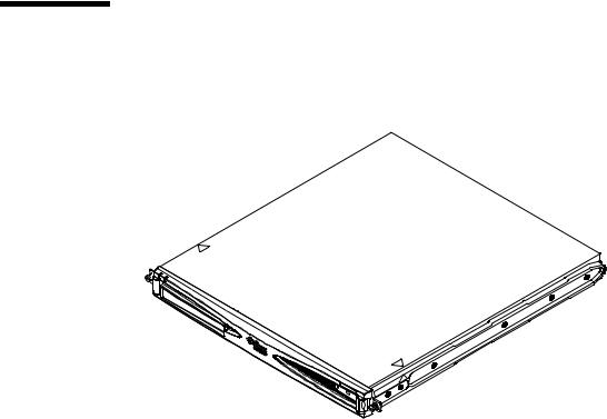
1.1Overview of the Sun Fire V120 and Netra 120 Servers
FIGURE 1-1 The Sun Fire V120 Server
The Sun FireTM V120 and NetraTM 120 servers are single-processor, thin (1U) servers designed primarily for use by telecommunications carriers and internet service providers. They are also suitable for use within corporate customer networks, wherever there is a need to maximize the density of high-performance Solaris servers.
The Sun Fire V120 and Netra 120 servers are identical except that the Sun Fire V120 is powered by an AC supply and the Netra 120 by –48VDC/–60VDC supplies. This is the only difference between the two models.
The servers both have the following features:
■Rackmounting enclosure with single power supply
■UltraSPARCTM IIe+ 550 or 650 MHz processor
■Four DIMM sockets accepting 256 MB or 512 MB PC133 memory modules (giving a maximum of 2 GB of memory)
■One 33-MHz, 32-bit, 5V PCI card slot
■Two 10/100 Mbps RJ-45 Ethernet ports
■Console/Lights-Out Management (LOM) RJ-45 serial port
1-2 Sun Fire V120 and Netra 120 Server User’s Guide • December 2001

■Second RJ-45 serial port
■Optional DVD or CD-ROM drive
■Support for up to two low-profile, 3.5-inch Fast-40 (Ultra2SCSI) disks
■Support for up to two USB connections
■External Fast-40 (Ultra2SCSI) Multimode 68-pin port
These servers are designed to be rackmounted. Their components are housed in a casing with the following dimensions:
■Height: 1.72 inches (43.6 mm)
■Width: 17.2 inches (436.7 mm)
■Depth: 18.8 inches (478 mm)
■Weight (when all option modules are installed): 10 kg (22 lb)
1.2Contents of the Ship Kit
TABLE 1-1 Contents of the Ship Kit
Item |
Quantity |
Part Number |
|
|
|
19-inch rackmounting brackets |
4 |
340-5819-02 |
Cable management bracket |
1 |
340-6151-01 |
Sun slide rail |
2 |
540-4362-01 |
RJ-45 to RJ-45 patch cable for Ethernet or serial connection |
2 |
530-2093-01 |
RJ-45 to DB-25 adapter |
1 |
530-2889-02 |
DC connector kit (for Netra 120 systems only) |
1 |
565-1644-01 |
10-32 UNF Sun rackmounting screw kit |
1 |
565-1645-01 |
Side-mounting bracket screw kit |
1 |
565-1654-01 |
Sun Fire V120 and Netra 120 Server User’s Guide (this manual) |
1 |
816-2090-10 |
Sun Fire V120 and Netra 120 Set Up Poster |
1 |
816-2091-xx |
Sun Fire V120, Netra 120, and Netra T1 Servers: Safety and |
1 |
806-6135-xx |
Compliance Guide |
|
|
Sun Fire V120 and Netra 120 Server Product Notes |
1 |
816-2093-xx |
|
|
|
Chapter 1 Introduction 1-3

FIGURE 1-2 Contents of the Ship Kit
1-4 Sun Fire V120 and Netra 120 Server User’s Guide • December 2001

1.3Optional Hardware and Software
TABLE 1-2 lists the customer-installable hardware components and software packages that are available for the Sun Fire V120 and Netra 120 servers. To order any of these options, contact your local Sun sales representative.
TABLE 1-2 Customer-Installable Hardware and Software
Optional Components |
Part Number |
|
|
19-inch rackmount kit |
X7085A |
23-inch rackmount kit |
X6966A |
24-inch rackmount kit |
X6967A |
600-mm rackmount kit |
X6968A |
Internal CD-ROM drive |
X7088A |
Internal DVD-ROM drive |
X1288A |
18 GB hard disk |
X5239A |
36 GB hard disk |
X5244A |
256 MB DIMM |
X7091A |
512 MB DIMM |
X7092A |
Power splitter cable |
X7098A |
5-pack serial port adapter |
X6973A |
Gigabit Ethernet PCI Adapter 2.0 |
X1141A |
FastEthernet 10/100Base-T F/W UltraSCSI PCI Adapter 1.0 |
X1032A |
FastEthernet 10/100Base-T PCI Adapter 2.0 |
X1033A |
Quad FastEthernet PCI Adapter (QFE) |
X1034A |
High-Speed Serial Interface PCI Adapter 2.0 |
X1155A |
ATM PCI Adapter 4.0 (155-Mbps Multi-Mode Fiber Interface) |
X1157A |
ATM PCI Adapter 4.0 (155-Mbps UTP Interface) |
X1158A |
Dual-Channel UltraSCSI Differential PCI Host Adapter |
X6541A |
Serial Asynchronous Interface PCI Adapter |
X2156A |
Crypto Accelerator PCI Adapter |
X1133A |
Single-Loop FC-AL PCI Host Adapter |
X6729A |
Gigabit Ethernet and FC-AL PCI Adapter |
X2069A |
|
|
Chapter 1 Introduction 1-5
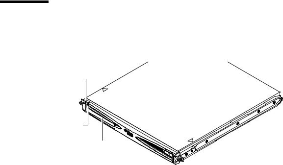
1.4Front Panel
The illustration below shows the location of the Power and Fault LEDs, and the DVD-ROM drive bay.
Power LED
Fault LED |
DVD-ROM drive bay |
FIGURE 1-3 The Front Panel of the Sun Fire V120 and Netra 120 Servers
1-6 Sun Fire V120 and Netra 120 Server User’s Guide • December 2001
Loading...