


U N DERC OU N TER I CE M ACH I NE
INSTALLATION & OPERATION
C O NT E NTS
Ice Machine Installation |
4 |
Installation Checklist |
16 |
Ice Machine Features |
17 |
Ice Machine Operation |
18 |
Ice Machine Care |
23 |
Troubleshooting Guide |
28 |
Service Information |
30 |
Sub-Zero Warranty |
31 |
Features and specifications indicated herein and on the website are subject to change at any time without notice. Check our website, subzero.com, for the most up-to-date specifications.
SUB-ZERO® is a registered trademark of Sub-Zero, Inc.
As you follow these instructions, you will notice WARNING and CAUTION symbols. This blocked information is important for the safe and efficient installation of Sub-Zero equipment. There are two types of potential hazards that may occur during installation.
signals a situation where minor injury or product damage may occur if you do not follow instructions.
states a hazard that may cause serious injury or death if precautions are not followed.
Another footnote we would like to identify is IMPORTANT NOTE: This highlights information that is especially relevant to a problemfree installation.

S UB -Z ERO ICE MACHINE I NSTALLATION |
AN D OP E RAT I ON |
THANK YOU
Congratulations on the purchase of your Sub-Zero ice machine. It produces the same high quality clear ice that you would expect from Sub-Zero.
The importance of the installation of the ice machine cannot be overemphasized. Installation should be done by a qualified installer.
Before you begin the installation process, it is recommended that you read the entire
installation instructions. There are key details that you should take special care to observe during the installation. By reading these instructions carefully, you will make the installation process easier, problem-free and, most importantly, safe.
Any questions or problems about the installation should be directed to your Sub-Zero dealer or Sub-Zero customer service at 800-222-7820. You can also visit our website at subzero.com.
The Sub-Zero ice machine is protected by a warranty that is one of the finest in the industry. Take a moment to read the warranty statement on page 31 and refer to it should service become necessary.
The operation information in this book will answer most of your questions about the features, operation and maintenance of your ice machine. If you have questions that are not addressed here, call Sub-Zero customer service at 800-222-7820 or visit our website
at subzero.com.
IMPORTANT NOTE: Your Sub-Zero ice machine is designed and manufactured with the highest regard for safety and performance. It meets or exceeds the standards of UL and CUL. Sub-Zero assumes no liability or responsibility of any kind for products manufactured by Sub-Zero that have been altered in any way, including the use of any parts and/or other components not specifically approved by Sub-Zero. Sub-Zero reserves the right to make design changes and/or improvements at any time. Specifications and designs are subject to change without notice.
Do not operate equipment that has been misused, abused, neglected, damaged, or altered/modified from that of original manufactured specifications.
C O NTA CT
IN FO RMA TI ON
Sub-Zero customer service: 800-222-7820
Website: subzero.com
PRODU CT RE GISTRA TION C A R D
The packet containing this manual also includes warranty information. Warranty coverage begins the day your new ice machine is installed.
IMPORTANT NOTE: Complete and mail the product registration card as soon as possible to validate the installation date. If you do not return your product registration card, Sub-Zero will use the date of sale to the Sub-Zero dealer as the first day of warranty coverage for your new ice machine.
3

SUBZE RO ICE MACHINE I NSTA LL AT IO N
A CC ESSO RIE S
Optional accessories are available through your Sub-Zero dealer. To obtain local dealer information, visit the Showroom Locator section of our website, subzero.com.
ICE MACH INE REQ UIREMENT S
Models UC-15I and UC-15IO must have open site (gravity) drain available
(see page 8).
A grounded, polarized electrical power supply on a separate circuit servicing only this appliance is required. If GFCI (ground fault circuit interrupter) is required by your local electrical code or in an outdoor installation, it must be breaker type, not outlet type (see page 7).
Must have cold water supply line available at ice machine (see page 8).
Clearance and air temperature requirements must be met (see page 6).
If built into a cabinet, ice machine must be removable for yearly cleaning procedure (see page 23).
Proper installation requires connection to the water supply, a drain and a dedicated electrical circuit. These connections are the responsibilities of the owner/operator. Improper connections can result in personal injury, substantial property damage and erratic machine operation. If you are unsure of your ability to safely connect the ice machine, consult qualified professionals or contact Sub-Zero.
IMPORTANT NOTE: Failure to follow these installation guidelines may affect warranty coverage.
The model and serial number are listed on the rating plate in the upper left corner of the ice bin and on the back of the unit. Refer to the illustration below.
MO DE L/ SE RI AL NU MBER LO CA TI ON
Models UC-15I, UC-15IP, UC-15IO & UC-15IPO
Rating plate
|
Dimensions in parentheses are in |
4 |
millimeters unless otherwise specified. |
S UB -Z ERO ICE MACHINE I NSTALLATION
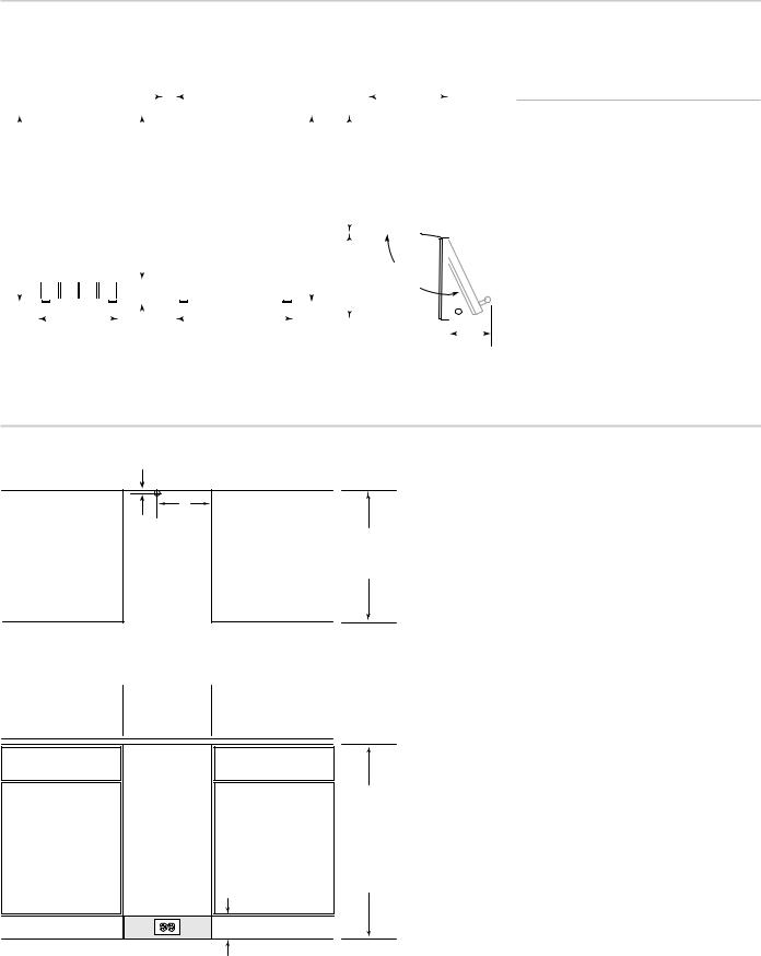
OV ERALL DI M E NS IONS
Models UC-15I, UC-15IP, UC-15IO & UC-15IPO
|
|
|
|
|
|
|
|
|
|
|
|
|
|
|
|
|
|
|
|
|
|
|
|
|
|
|
1 |
11/16 "*(43) |
|
|
|
|
|
|
|
|
|
|
|
|
143/4" |
|
|
|
|
|
||
|
|
|
|
|
|
|
|
|
|
|
|
|
|
|
|
|
|
|
|
|
|
|
|
|
|
|
|
|
|
|
|
|
|
|
|
|
(375) |
|
|
|
|
|
||||||
|
|
|
|
|
|
|
|
|
|
|
|
|
|
|
|
|
|
|
|
|
|
|
|
|
|
|
|
|
|
|
|
|
|
|
|
|
|
|
|
|
|
|
|
|
||||
|
|
|
|
|
|
|
|
|
|
|
|
|
|
|
|
|
|
|
|
|
|
|
|
|
|
|
|
|
|
|
|
|
|
|
|
|
|
|
|
|
|
|
|
|
|
|
|
|
|
|
|
|
|
|
|
|
|
|
|
|
|
|
|
|
|
|
|
|
|
|
|
|
|
|
|
|
|
|
|
|
|
|
|
|
|
|
|
|
|
|
|
|
|
|
|||
|
|
|
|
|
|
|
|
|
|
|
|
|
|
|
|
|
|
|
|
|
|
|
|
|
|
|
|
|
|
|
|
|
|
215/16" |
|
|
|
|
|
|
|
|
|
|
||||
|
|
|
|
|
|
|
|
|
|
|
|
|
|
|
|
|
|
|
|
|
|
|
|
|
|
|
|
|
|
|
|
|
|
(54 |
1) |
|
|
|
|
|
|
|
|
|
|
|||
|
|
|
|
|
|
|
|
|
|
|
|
|
|
|
|
|
|
|
|
|
|
|
|
|
|
|
|
|
|
|
|
|
|
|
|
|
|
|
|
|
|
|
|
|
|
|
||
|
|
|
|
|
|
|
|
|
|
|
|
|
|
|
|
|
|
|
|
|
|
|
|
|
|
|
|
|
|
|
|
|
|
|
|
|
|
|
|
|
|
|
|
|
|
|
|
|
335/8" |
|
|
|
|
|
|
|
|
|
|
|
295/8" |
|
|
|
|
|
|
|
|
|
|
|
|
|
335/8" |
|
|
|
|
|
|
|
|
|
|
|
|
|
|||||||||
(8 54) |
|
|
|
|
|
|
|
|
|
|
|
|
(752) |
|
|
|
|
|
|
|
|
|
|
|
|
|
|
|
(8 54) |
|
|
|
|
|
|
|
|
|
|
|
|
|
|
|||||
|
|
|
|
|
|
|
|
|
|
|
|
|
|
|
|
|
|
|
|
|
|
|
|
|
|
|
|
|
|
|
|
|
|
|
|
|
|
|
|
|
|
|
|
|
|
|
|
|
|
|
|
|
|
|
|
|
|
|
|
|
|
|
|
|
|
|
|
|
|
|
|
|
|
|
|
|
|
|
|
|
|
|
|
|
|
|
|
|
|
|
|
|
|
|
|
|
|
|
|
|
|
|
|
|
|
|
|
|
|
|
|
|
|
|
|
|
|
|
|
|
|
|
|
|
|
|
|
|
|
|
|
|
|
|
|
|
|
|
|
|
|
|
|
|
|
|
|
|
|
|
|
|
|
|
|
|
|
|
|
|
|
|
|
|
|
|
|
|
|
|
|
|
|
|
|
|
|
|
|
|
|
|
|
|
|
|
|
|
|
|
|
||||
|
|
|
|
|
|
|
|
|
|
|
|
|
|
|
|
|
|
|
|
|
|
|
|
|
|
|
|
|
|
|
|
|
|
|
|
|
|
|
|
|
|
|
|
|
|
|
|
|
|
|
|
|
|
|
|
|
|
|
|
|
|
|
|
|
|
|
|
|
|
|
|
|
|
|
|
|
|
|
|
|
|
|
|
|
|
|
|
|
|
|
|
|
|
|
|||
|
|
|
|
|
|
|
|
|
|
|
|
|
|
|
|
|
|
|
|
|
|
|
|
|
|
|
|
|
|
|
|
|
|
|
|
|
18" |
|
|
|
1 5˚ |
|
|
|
||||
|
|
|
|
|
|
|
|
|
|
|
|
|
|
|
|
4" |
(102) |
|
|
|
|
|
|
|
|
|
|
|
|
|
|
(457) |
|
DOOR SWI |
NG |
|
|
|
||||||||||
|
|
|
|
|
|
|
|
|
|
|
|
|
|
|
|
|
|
|
|
|
|
|
|
|
|
|
|
|
|
|
|
|
||||||||||||||||
|
|
|
|
|
|
|
|
|
|
|
|
|
|
|
|
|
|
|
|
|
|
|
|
|
|
|
|
|
|
|
|
|
|
|
|
|
|
|
|
|
|
|
|
|||||
|
|
|
|
|
|
|
143/4" |
|
|
|
|
|
|
|
|
|
|
|
|
|
|
|
|
215/16" |
|
|
|
|
|
|
|
|
|
|
|
|
|
|
|
|
|
|
|
|||||
|
|
|
|
|
|
|
|
|
|
|
|
|
|
|
|
|
|
|
|
|
|
|
|
|
|
|
|
|
|
|
|
|
|
|
|
|
|
|
|
|
|
|||||||
|
|
|
|
|
|
|
(3 75) |
|
|
|
|
|
|
|
|
|
|
|
|
|
|
|
|
|
|
|
(541) |
|
|
|
|
|
|
|
|
|
|
|
|
|
|
|
|
|
|
|
||
|
|
|
|
|
|
|
|
|
|
|
|
|
|
|
|
|
|
|
|
|
|
|
|
|
|
|
|
|
|
|
|
|
|
|
|
|
|
|
|
|
|
|
|
|
||||
|
|
|
|
|
|
|
|
|
|
|
|
|
|
|
|
|
|
|
|
|
|
|
|
|
|
|
|
|
|
|
|
|
|
|
|
|
|
|
|
|
|
|
|
|
|
|
|
|
|
|
|
|
FRONT |
|
|
VIEW |
|
|
|
|
|
|
|
|
|
|
SI DE VI EW |
|
|
|
TO P VI |
EW |
|
61/2" |
|||||||||||||||||||||||
|
|
|
|
|
|
|
|
|
|
|
|
|
|
|
|
|
|
|
|
|||||||||||||||||||||||||||||
|
|
|
|
|
|
|
|
|
|
|
|
|
|
|
|
|
|
|
(1 65 ) |
|||||||||||||||||||||||||||||
A L L MO DE LS
Overall Width |
143/4" (375) |
Overall Height (levelers in) |
335/8" (854) |
Overall Depth |
23" (584) |
|
|
Minimum Door Clearance |
18" (457) |
|
|
Rough Opening Width |
151/4" (387) |
Rough Opening Height |
341/2" (876) |
Minimum Height Required |
|
(levelers in) |
335/8" (854) |
Rough Opening Depth |
24" (610) |
|
|
Dimensions may vary ±1/8" (3).
*Doe s not include |
dor |
panel |
|
|
|
|
|
I NS TAL LATI |
ON |
SPEC |
IFIC |
|
ATI ONS |
|
|
|
|
|
|
8" |
|
|
|
|
|
1/2" |
(2 03 |
) |
|
|
|
|
|
|
|
24" |
|
||
|
|
(13 |
) |
|
|
(610) |
|
|
|
|
|
|
|
ROU |
GH |
|
|
LOC |
AT ION OF |
OPEN |
IN G |
||
|
|
WAT ER LINE |
|
DE |
PTH |
||
TOP VIEW
 151/4"min (3 87 )
RO UGH
OP EN ING WID TH
|
|
|
|
|
|
|
|
LO CA TE |
|
||
PO |
SIT ION |
|
OU |
TL |
ET |
EL |
EC |
TR |
ICA |
L |
|
WI |
TH |
GROUN |
|
DI |
NG |
|
WI |
THI |
N |
|
|
PRO |
NG |
ON |
RI |
GHT |
SH |
AD |
ED |
AR |
EA |
||
|
|
|
|
|
|
|
|
|
|
|
4" (102 ) |
341/2" (876)
ROU |
GH |
OPEN |
IN G |
HEIG |
HT |
335/8" (854) MI NIM UM HEIG HT REQU IRE D
FRON T VIEW |
5 |
SUBZE RO ICE MACHINE I NSTA LL AT IO N
LOC ATI ON OF IC E MA C HI NE |
ARE A RE Q UI RE M E NTS |
The location selected for the ice machine must meet the following criteria. If any of these criteria are not met, select another location.
The ice machine may be built into a cabinet, however the location must allow removal of the ice machine for cleaning and servicing. Service diagnostics are performed from the top of the ice machine.
The location must be free of airborne and other contaminants.
Do not place the unit within 18" (457) of a trash compactor or trash/recycling container.
The air temperature must be at least 50°F (10°C), but must not exceed 100°F (38°C) for models UC-15I and UC-15IP and 110°F (43°C) for models UC-15IO and UC-15IPO.
The location must not be near heat-generat- ing equipment.
The location must not obstruct air flow through the kickplate (airflow is in and out the front of the ice machine).
The location must allow enough clearance for water, drain and electrical connections at the rear of the ice machine.
Models UC-15IO and UC-15IPO may be installed outside.
The ice machine must be protected if it will be subjected to ambient temperatures below 32°F (0°C). Component failure caused by exposure to freezing temperatures is not covered by the warranty. See page 27.
Before moving the ice machine in place, be sure the finished opening dimensions, electrical and plumbing locations are accurate. Refer to pages 7–11.
Be sure your plumber, electrician and cabinet installer have this information before finishing work is completed.
Models UC-15I and UC-15IO are gravity drain models that require a drain tube that is pitched down from the outlet at the back of the unit to the sanitary sewer connection. Models UC-15IP and UC-15IPO have a built in drain pump that will pump water up to a drain point, such as a nearby sink. Refer to specifications on pages 8–9.
IMPORTANT NOTE: If the ice machine is installed in a corner, the door swing may be limited due to handle contact with the wall or cabinet face.
IMPORTANT NOTE: The floor under the
ice machine must be at the same level as the surrounding finished floor.
IMPORTANT NOTE: When you move the unit using a hand truck or dolly, position the dolly on the side of the unit and secure the door so it does not open while transporting the unit.
Any finished flooring should be protected with appropriate material to avoid any damage from moving the unit.
6

S UB -Z ERO ICE MACHINE I NSTALLATION
ELE CTR IC AL REQ UI RE ME NTS
Prepare electrical circuit before installation of your ice machine. Installation requires a grounded (three-prong), polarized receptacle with a separate fuse/circuit breaker in an electrical service box.
V OLTA GE
Do not use an extension cord or twoprong adapter. Electrical ground is required on this appliance. Do not remove the power supply cord ground prong.
All electrical work, including wire routing and grounding, must conform to local, state and national electrical codes. The following precautions must be observed:
The ice machine must be grounded.
A separate fuse/circuit breaker must be provided for each ice machine.
The maximum allowable voltage variation is +/-10% of the rated voltage at ice machine start-up (when the electrical load is highest).
The minimum wire size is #14 for less than 100 feet (30.5 m) or #12 for more than 100 feet (30.5 m) to 200 feet (61 m) (solid copper conductor only). The recommended breaker is 15 amp. Local or state electrical code, length of run or materials used, can increase the minimum wire gauge required. A qualified electrician must determine the proper wire size, although #14 is the minimum size allowed.
Dimensions in parentheses are in millimeters unless otherwise specified.
IMPORTANT NOTE: Observe correct polarity of incoming line voltage.
Incorrect polarity can lead to erratic ice machine operation and a safety issue.
M I NI MUM CI RCU IT RE QU IR EM E N T
The minimum circuit requirement is used to help select the wire size of the electrical supply. (Minimum circuit requirement is not the ice machine’s running amp load.)
M A X IM UM |
B R EA KE R |
SI ZE |
A N D |
M I NI MUM |
CI RCU IT |
A MP E RAG E |
|
|
|
|
|
Voltage/Phase/Cycle |
|
115/1/60 |
|
|
|
||
Maximum Fuse/Circuit Breaker |
15 |
||
|
|
|
|
Minimum Circuit Amps |
|
4.1 |
|
|
|
|
|
GF CI R EQ UI RE ME NT S
For Models UC-15IO and UC-15IPO or if a GFCI (ground fault circuit interrupter) is required by local electrical code, it must be breaker type.
I M PO RTA N T NO T E
You must follow all National Electrical Code regulations. In addition, be aware of local codes and ordinances when installing your services.
7

I MPOR TAN T NO TE
Plumbing must conform to state and local codes.
SUBZE RO ICE MACHINE I NSTA LL AT IO N
PL UMB ING REQU IREMENTS
WA T E R S U PP LY
Prepare water supply line and drain before installation of your ice machine. Installation requires a minimum 1/4" ID copper cold water line and compression fitting (not supplied). Models UC-15I and UC-15IO are supplied with a drain hose for gravity draining. The optional drain pump or pump models UC-15IP and UC-15IPO must be purchased if a gravity drain is not possible. Both drain methods require routing to an open site drain. Do not connect directly to drain line as bacteria from drain line may contaminate the ice machine.
The included water filter is designed to inhibit scale formation, filter sediment, and remove chlorine odor and taste. The life expectancy of the water filter is 6 months during normal usage. The ice machine control board will monitor water usage and indicate when replacement is required.
WA T E R I NLE T LI NE S
Follow these guidelines to install water inlet lines:
Do not connect the ice machine to a hot water supply. Be sure all hot water restrictors installed for other equipment are working. (Check valves on sink faucets, dishwashers, etc.)
If water pressure exceeds the maximum recommended pressure (80 psi–551.5 kPA), obtain a water pressure regulator from your local plumbing contractor.
Install a water shut-off valve for the ice making water lines.
Insulate the water inlet line to prevent condensation.
DR AI N CO N NE CTI O NS
Follow these guidelines when installing drain lines to prevent drain water from flowing back into the ice machine and storage bin:
Drain lines must have a 11/2" drop per 5 feet of run (2.5 cm per meter), and must not create traps.
The floor drain must be large enough to accommodate drainage from all drains.
Drain pump discharge line must terminate at an open site drain.
Maximum rise – 12 feet (3.7 m)
Maximum run – 100 feet (30.5 m)
AP P RO X IM AT E H EI G H T O F
IC E M ACH IN E D RA IN
|
Standard installation |
5" (127) |
|
||
|
|
|
|
|
|
|
|
|
|
|
|
Improper drainage can lead to water flowing back into ice machine and poor performance.
8
S UB -Z ERO ICE MACHINE I NSTALLATION
PLUM BI NG REQU IREMENTS |
|
|
|
|
WATE R S UPP LY AND DRAIN |
L INE SIZIN G/ CO NN E CT I ON S |
|
||
|
|
|
|
|
|
Water |
Water |
Ice Machine |
Tubing Size up to |
|
Temperature |
Pressure |
Fitting |
Ice Machine Fitting |
|
|
|
|
|
Ice Making |
50°F (10°C) Min. |
20 psi (137.9 kPA) Min. |
1/4" (6.4) ID |
1/4" (6.4) minimum |
Water Inlet |
80°F (27°C) Max. |
80 psi (551.5 kPA) Max. |
Copper Tubing |
inside diameter |
|
|
|
|
|
Water Outlet |
|
|
3/4" (19) |
3/4" (19) minimum |
UC-15I and |
— |
— |
Hose Barb |
inside diameter |
UC-15IO |
|
|
|
|
|
|
|
|
|
Water Outlet |
|
|
3/8" (9.5) |
3/8" (9.5) |
UC-15IP and |
— |
— |
Hose |
ID minimum |
UC-15IPO |
|
|
|
|
|
|
|
|
|
NOTE: If air temperature is less than 60°F (16°C), water temperature must be equal to or greater than 50°F (10°C).
IMPORTANT NOTE: Although the ice machine has been designed to be serviced in place, in some cases it may be necessary to pull the unit out for service. For that reason do not restrict access to the unit at the front, top and bottom.
If a floor is to be installed after the ice machine, shims the thickness of the floor should be installed under the unit to keep the ice machine level with the floor. Also, allow 1/8" (3) clearance on each side of the unit for protruding screw heads.
Installations on a slab: Use a Model UC-15IPO or UC-15IP, with built-in drain pump and pump the water to the point of drainage. Drain pump models will pump 12 feet (3.7 m) high.
Installations over a crawl space or basement: If there is not enough room behind the ice machine for a drain/waste water receptacle, the drain will have to be below the floor.
Dimensions in parentheses are in millimeters unless otherwise specified.
I M PO RTA N T NO T E
Plumbing must conform to state and local codes.
9
SUBZE RO ICE MACHINE I NSTA LL AT IO N
INST ALL ATI ON
IN ST ALLATIO N PR O C EDU RE
1)Prepare the site by following the instructions under Electrical Requirements and Plumbing Requirements on pages 7–9.
2)Remove ice machine from carton.
3)Inspect for damage.
4)Remove literature/warranty packet and drain hose from inside the ice machine.
5)Adjust leg levelers. Refer to Leveling on page 12.
6)Reverse door if desired. See pages 12–13.
7)Gravity drain model: Install drain hose to drain on back of ice machine and route to open site drain. Refer to Plumbing Requirements on pages 8–9.
Pump model: Route drain tubing through drain fitting on the back of the ice machine and install drain hose on drain pump.
Route other end of drain tubing to drain site. Refer to Plumbing Requirements on pages 8–9.
8)Use compression fitting to connect the Water Inlet on back of ice machine to the prepared 1/4" ID cold water line. Refer to Plumbing Requirements on pages 8–9.
9)Open the shut-off valve on the water line.
10)Check all visible connections for water leakage. Failure to do so could cause flooding.
11)Connect electrical plug to grounded (threeprong), polarized outlet. See Electrical Requirements on page 7.
The ice machine must be grounded in accordance with national and local electrical codes. Do not use an extension cord or adapter.
Improper water supply and drain connections can result in personal injury and substantial property damage. These connections are the responsibility of the owner/operator.
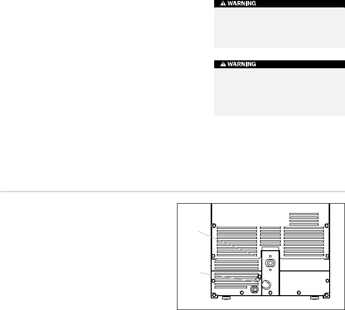
12)Place ice machine back in position and check leveling again. Make any necessary adjustments.
Drain |
Fitting |
Water |
Inlet |
Connect to drain
Dimensions in parentheses are in
10 |
millimeters unless otherwise specified. |
 Loading...