


COMMERCIAL GAS WATER HEATERS
FOR MODELS:
SERVICE HANDBOOK
HIGH EFFICIENCY COMMERCIAL GAS SERIES
•SUF 60 120
•SUF 100 150
•SUF 100 199
•SUF 100 250
•SUF 130 300
•SUF 130 400
PRINTED 0509 |
1 |
198152-002 |
|
|

ULTRAFORCE COMMERCIAL GAS WATER HEATER SUF 120 thru 400 SERVICE HANDBOOK
TABLE OF CONTENTS
INTRODUCTION............................................................... |
2 |
QUALIFICATIONS............................................................ |
2 |
TOOLS REQUIRED......................................................... |
3 |
GENERAL INFORMATION................................................ |
4 |
GAS PRESSURE SPECIFICATIONS ................................ |
4 |
INSTALLATION QUICK TIPS – SUF 120 and 150 GAS |
|
PRESSURE ..................................................................... |
5 |
ADJUSTMENT PROCEDURE: ......................................... |
5 |
GAS PRESSURE ............................................................. |
5 |
SUF120 AND 150 MODELS.............................................. |
5 |
HIGH ALTITUDE INSTALLATIONS ................................... |
5 |
SUF 120 - 150 ................................................................. |
5 |
INSTALLATION QUICK TIPS - SUF 199 AND 250 GAS |
|
PRESSURE ..................................................................... |
6 |
ADJUSTMENT PROCEDURE:.......................................... |
6 |
GAS PRESSURE ............................................................. |
6 |
SUF 199 AND 250 MODELS ............................................ |
6 |
HIGH ALTITUDE INSTALLATION...................................... |
6 |
INSTALLATION QUICK TIPS - SUF 300, 400 GAS |
|
PRESSURE...................................................................... |
7 |
ADJUSTMENT PROCEDURE:.......................................... |
7 |
GAS PRESSURE.............................................................. |
7 |
SUF 300,400,....................................................................7 |
|
HIGH ALTITUDE ADJUSTMENT ...................................... |
7 |
SUF 300,400,....................................................................7 |
|
INSTALLATION TIPS - SUF 300, 400 ............................... |
8 |
VENTING TABLES SUF 120 – 250.................................... |
9 |
VENTING TABLES SUF 300,400,.....................................9 |
|
VENTING - ALL MODELS – SINGLE PIPE POWER VENT – |
|
USING ROOM AIR.......................................................... |
10 |
VENTING – ALL MODELS – TWO PIPE DIRECT VENT – |
|
USING OUTSIDE AIR..................................................... |
11 |
VENT TERMINATION – DIRECT VENT – ALL MODELS. .12 |
|
DIRECT VENTING – ALL MODELS................................. |
13 |
CONTROL OVERVIEW .................................................. |
14 |
CONTROL OVERVIEW – ALL MODELS.......................... |
14 |
ADJUSTING TANK TEMPERATURE – OPERATING SET |
|
POINT - DIFFERENTIAL................................................. |
15 |
CHANGING THE DISPLAY UNITS.................................. |
16 |
FAULT AND WARNING CONDITIONS – ADVANCED |
|
DIAGNOSTIC INFORMATION......................................... |
17 |
ACCESS TO THE CURRENT FAULT OR WARNING....... |
18 |
VIEWING THE FAULT HISTORY - VIEWING |
|
INFORMATION ABOUT THE HEATER............................ |
19 |
CONTROL SEQUENCE (TYPICAL ALL MODELS)......... |
20 |
CONTROL SEQUENCE FLOW CHART........................... |
21 |
CONTROLS – CENTRAL CONTROL BOARD – CCB ...... |
22 |
CONTROLS – GAS VALVE SUF 120............................... |
23 |
CONTROLS – GAS VALVE SUF 150............................... |
23 |
CONTROLS – GAS VALVE SUF 199 and 250.................. |
24 |
ADJUSTMENT PROCEDURE:........................................ |
24 |
GAS PRESSURE ........................................................... |
24 |
SUF 199 AND 250 MODELS .......................................... |
24 |
CONTROLS – GAS VALVE SUF 199 and 250.................. |
25 |
CONTROLS – GAS VALVE , ORIFICE CHART– SUF300,400,...................................................................26 CONTROLS – PRESSURE SWITCHES – ALL MODELS..27 CONTROLS – PRESSURE SWITCHES – SUF 120 through
250................................................................................. |
28 |
CONTROLS – PRESSURE SWITCHES – SUF 300,400,. .29 |
|
CONTROLS – CONNECTIONS, IGNITER, FLAME |
|
SENSOR, SIGHT GLASS, POWERED ANODES............. |
30 |
HOT SURFACE IGNITER / FLAME SENSOR / CONTROL |
|
TIMING........................................................................... |
31 |
BLOWER SPEED CONTROL SUF 199 AND 250............. |
32 |
VARIABLE FREQUENCY DRIVE – SUF 400................... |
33 |
VARIABLE FREQUENCY DRIVE - BLOWER SPEED AND |
|
PRESSURE READINGS.................................................. |
34 |
WIRING DIAGRAM – SUF 120 – 300 .............................. |
35 |
WIRING DIAGRAM – SUF 400,.......................................36
State Water Heaters – Technical Training Department 1 |
Ashland City, Tennessee © 2009 |
Servicing should only be performed by a Qualified Service Agent |
198152-002 |
ULTRAFORCE COMMERCIAL GAS WATER HEATER
SUF 120 thru 400 SERVICE HANDBOOK
INTRODUCTION
The service handbook is designed to aid in |
inclusive. If you are experiencing a problem |
||||||||||||||
servicing |
and |
trou bleshooting |
S tate |
W ater |
not covered in this handbook, please contact |
||||||||||
Heaters Ultra Force |
SUF commercial water |
State Water Heaters Technical Information at |
|||||||||||||
heaters |
i n t he |
f ield. |
|
No |
duplication |
or1-800-365-0024, |
by |
e |
at |
||||||
reproduction |
of |
t his |
bo ok m ay be |
m adehelp@statewaterheaters.com or your local |
|||||||||||
without the express written authorization of |
State Water Heater representative for further |
||||||||||||||
State Water Heaters . |
|
|
|
|
|
|
assistance. |
|
|
|
|
||||
The |
fol lowing |
tex t |
and |
i llustrations |
w illOur website:www.statewaterheaters.com |
|
|||||||||
provide you with a step by step procedure to |
is also a resource for installation and service |
||||||||||||||
verify pr oper |
i nstallation, |
opera tion, |
and information. Thi s |
handbook i s i ntended |
for |
||||||||||
troubleshooting procedures. Additional quick |
use by licensed plumbing professionals and |
||||||||||||||
reference |
data i s i ncluded |
to |
assist |
you in reference should be made to the installation |
|||||||||||
servicing these products. |
|
|
|
|
|
manual accom panying the |
prod uct. |
This |
|||||||
|
|
|
|
|
|
|
|
|
|
|
|||||
The information contained in this handbook |
handbook contains supplemental information |
||||||||||||||
is |
designed |
to |
answer |
co mmonly |
face dto the produ ct’s |
i nstallation |
and |
ope ration |
|||||||
situations enc ountered |
in |
the |
ope ration |
of |
manual. |
|
|
|
|
||||||
this product line and |
is |
not meant to be |
all |
|
|
|
|
|
|||||||
QUALIFICATIONS
ANSI Z223.1 Sec 3.3.83
"Qualified Agency"
"Any individual, firm, corporation or company |
Service of this water heater requires ability |
||||||||||||||
that ei ther |
i n |
person o r |
|
through |
equivalent to |
th at |
of a Qual ified S ervice |
||||||||
representative |
i s e ngaged i n |
an d |
iAgents |
(l icensed t radesman) |
i n |
the |
fi eld |
||||||||
responsible for (a) the installation, testing or |
involved. Installation skills such as plumbing, |
||||||||||||||
replacement |
of |
g as |
p iping |
or |
(b) |
theair supp ly, |
vent ing, gas |
s upply, e lectrical |
|||||||
connection, i nstallation, |
testing, |
re pair |
or supply |
are |
required in addition to electrical |
||||||||||
servicing of appliances and equipment; that |
testing |
ski lls. S ome |
pro ducts m ay requ ire |
||||||||||||
is experienced in such work; that is familiar |
combustion |
|
testi |
ng |
equipment |
and |
|||||||||
with all precautions required; and |
that has |
certification. |
If |
you |
do |
not |
possess |
these |
|||||||
complied w ith al l |
the |
re quirements o f |
the skills or do |
not have the proper tools you |
|||||||||||
authority having jurisdiction." |
|
|
|
should |
not |
attem pt |
to |
serv ice |
thi s |
w ater |
|||||
|
|
|
|
|
|
|
heater. |
|
|
|
|
|
|
|
|
State Water Heaters – Technical Training Department 2 |
Ashland City, Tennessee © 2009 |
Servicing should only be performed by a Qualified Service Agent |
198152-002 |
ULTRAFORCE COMMERCIAL GAS WATER HEATER
SUF 120 thru 400 SERVICE HANDBOOK
TOOLS REQUIRED
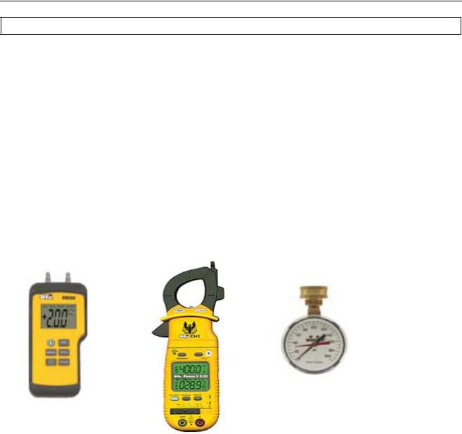
●ELECTRICAL MULTIMETER CAPABLE OF MEASURING CONTINUITY/ OHMS, AC
& DC VOLTS, AMPERES, MICROAMPERES, MILLIVOLTS, and FREQUENCY(Hz) ○ UEi Model DL289 or equivalent
●DIGITAL MANOMETER + 60” W. C. in .01” increments
Note: A digital manometer is required for testing pressure switches and can replace a gas pressure gauge, draft gauge or slack tube manometer for checking gas pressure.
○ UEi model EM200 or equivalent
●WATER PRESSURE GAUGE w/ LAZY HAND AND HOSE BIBB CONNECTION
●THERMOMETER
●1-1/16 INCH SOCKET WITH EXTENSION FOR ANODE REPLACEMENT
●SET OF NUMBERED DRILL BITS
|
|
|
|
WATER PRESSURE |
|
|
|
|
TEST GAUGE W/ LAZY |
|
|
|
|
HAND AND HOSE BIBB |
|
|
DIGITAL MULTIMETER |
|
CONNECTION |
DIGITAL MANOMETER |
|
|
|
|
|
|
|
|
|
|
|
|
|
|
State Water Heaters – Technical Training Department 3 |
Ashland City, Tennessee © 2009 |
Servicing should only be performed by a Qualified Service Agent |
198152-002 |

ULTRAFORCE COMMERCIAL GAS WATER HEATER
SUF 120 thru 400 SERVICE HANDBOOK
GENERAL INFORMATION
INSTALLATION REQUIREMENTS FOR THE |
|
|
|
equipment is installed in a crawl space or an attic, |
||||||||||||||||||||||
COMMONWEALTH OF MASSACHUSETTS |
|
|
|
the hard wired carbon monoxide detector with alarm |
|
|||||||||||||||||||||
For |
al l |
side w all |
terminated, |
hor izontally |
|
vented and battery back-up may be installed on the next |
||||||||||||||||||||
power vent, direct vent, and power direct vent gas |
adjacent |
f loor |
l evel. |
I n |
t he |
e vent |
t hat |
the |
||||||||||||||||||
fueled w ater heat ers |
installed |
i n ev ery dwelling, requirements of |
this subdivision can not be met at |
|||||||||||||||||||||||
building |
or |
structure used |
in w hole or |
in |
part f or the t ime of |
c ompletion |
of |
i nstallation, |
t he |
ow ner |
||||||||||||||||
residential |
pur poses, |
including |
t hose |
ow ned |
or shall have a period of thirty (30) days to comply with |
|
||||||||||||||||||||
operated by the Commonwealth and where the side |
the above requirements provided that during said |
|||||||||||||||||||||||||
wall exhaust vent termination is less than seven (7) |
thirty |
( 30) |
day |
p eriod, a |
bat tery op erated |
carbon |
||||||||||||||||||||
feet above finished grade in the area of the venting, |
monoxide detector with an alarm shall be installed |
|
||||||||||||||||||||||||
including but not limited to decks and porches, the |
APPROVED CARBON MONOXIDE DETECTORS |
|
||||||||||||||||||||||||
following requirements shall be satisfied: |
|
|
|
|
Each |
carbon |
monoxide |
de tector |
as |
r equired |
in |
|||||||||||||||
INSTALLATION OF CARBON MONOXIDE |
|
|
|
accordance with the above provisions shall comply |
||||||||||||||||||||||
DETECTORS |
|
|
|
|
|
|
|
|
|
|
|
|
with NFPA 720 and be ANSI/UL 2034 listed and |
|||||||||||||
At the time of installation of the side wall horizontal |
CSA certified. |
|
|
|
|
|
|
|
|
|||||||||||||||||
vented gas fueled equipment, the installing plumber |
SIGNAGE |
|
|
|
|
|
|
|
|
|
||||||||||||||||
or gas fitter shall observe that a hard wired carbon |
A m etal |
or |
p lastic i dentification |
plate s hall |
b e |
|||||||||||||||||||||
monoxide detector with an alarm and battery back- |
permanently mounted to the exterior of the building |
|||||||||||||||||||||||||
up |
is in stalled |
on |
t he f loor |
le vel wh ere |
t he |
g asat a minimum height of eight (8) feet above grade |
||||||||||||||||||||
equipment |
is |
t o |
b e |
i nstalled. |
In add ition, |
t hedirectly in line with the exhaust vent terminal for the |
|
|||||||||||||||||||
installing plumber or gas fitter shall observe that a |
horizontally vented gas fueled heating appliance or |
|
||||||||||||||||||||||||
battery |
operated |
or |
har d |
w ired |
carbon |
monoxide |
equipment. The sign shall read, in print size no less |
|
||||||||||||||||||
detector |
w ith |
an |
al arm |
i s |
i nstalled |
on |
eacthan one-half (1/2”) inch in size, |
|
|
|
|
|||||||||||||||
additional level of the dwelling, building or structure |
“GAS VENT DIRECTLY BELOW. KEEP CLEAR |
|
||||||||||||||||||||||||
served by the sidewall horizontal vented gas fueled |
|
|||||||||||||||||||||||||
equipment. |
It |
s hall |
b e |
the |
re sponsibility |
o f |
the |
|
|
OF ALL OBSTRUCTIONS.” |
|
|
|
|||||||||||||
property owner to secure the services of |
qualified |
|
|
|
|
|
|
|
|
|
|
|
||||||||||||||
licensed |
pr ofessionals |
for |
|
the i nstallation of |
har d |
|
|
|
|
|
|
|
|
|
|
|
||||||||||
wired carbon monoxide detectors. In the event that |
|
|
|
|
|
|
|
|
|
|
|
|||||||||||||||
the |
s ide |
wall |
hor izontally |
v ented |
gas |
fueled |
|
|
|
|
|
|
|
|
|
|
||||||||||
GAS PRESSURE SPECIFICATIONS
MODELS |
Natural |
Propane |
Natural |
Propane |
Natural |
Propane |
|
120-150 |
120-150 |
199-250 |
199-250 |
300/400/500 |
300/400/500 |
|
|
|
|
|
|
|
Maximum Gas Supply Pressure |
10.5” WC |
14.0“WC |
10.5“WC |
14.0“WC |
11.0”WC |
14.00”WC |
|
(2.59kPa) |
( 3.45kPa) |
(2.59kPa) |
( 3.45kPa) |
(2.74kPa) |
(3.49kPa) |
|
|
|
|
|
|
|
Nominal Gas Supply Pressure |
7.0”WC |
11.0“WC |
7.0“WC |
11.0“WC |
7.0”WC |
11.0”WC |
|
(1.74kPa) |
( 2.74kPa) |
(1.74kPa) |
( 2.74kPa) |
(1.74kPa) |
(2.74kPa) |
|
|
|
|
|
|
|
Minimum Gas Supply Pressure |
4.8”WC |
8.5“WC |
4.8”WC |
8.5“WC |
5.2”WC |
11.0“WC |
(Low Gas Press. Switch |
(1.20kPa) |
( 2.12kPa) |
(1.20kPa) |
( 2.12kPa) |
(1.54kPa) |
( 2.74kPa) |
Setting) |
|
|
|
|
|
|
|
|
|
|
|
|
|
Manifold Pressure |
4.0”WC |
10.0“WC |
0“WC |
0“WC |
4.00“WC |
10.0“WC |
|
(0.98kPa) |
(2.49 kPa) |
( 0 kPa) |
( 0 kPa) |
( 1.25kPa) |
( 2.49kPa) |
|
|
|
|
|
|
|
State Water Heaters – Technical Training Department 4 |
Ashland City, Tennessee © 2009 |
Servicing should only be performed by a Qualified Service Agent |
198152-002 |
ULTRAFORCE COMMERCIAL GAS WATER HEATER SUF 120 thru 400 SERVICE HANDBOOK
INSTALLATION QUICK TIPS – SUF 120 and 150 GAS PRESSURE
ADJUSTMENT PROCEDURE:
GAS PRESSURE
SUF120 AND 150 MODELS
Main line gas pressure to the water heater for natural gas should be between a maximum of 10.5"W.C. (2.59kPa) for natural gas, 14.0"W.C.(3.45kPa) for propane and a minimum of 4.8W.C.(1.18kPa) for Natural Gas, and 8.5"W.C. (2.08kPa) for Propane Gas.
A supply gas pressure regulator (service regulator) must be installed on the gas supply line within 10' (305 cm) of the unit.
Also see gas pressure specification table on page 4.
1.Check gas line pressure with a manometer. 2.Check manifold pressure gauge (manometer) connected to the manifold pressure tap on the gas control valve,
If full rate adjustment is required, remove cover screw from top of the gas control valve. Using a small screwdriver, turn adjusting screw clockwise to increase or counterclockwise to decrease gas pressure to obtain 4.0" W.C.(1 K pa) for natural gas and 10.0" W.C. (2.5 kPa) for L.P. Gas.
3.Cycle the burner on and off several times to check its operation.
4.Check the operation of the limit and operating
controls.
5.Check the vent system seams and joints and ensure that there is no discharge of flue products into the room.
6.Check the input rate.
HIGH ALTITUDE INSTALLATIONS SUF 120 - 150
For appliance installation locations with elevations above 6,500 feet (1982 meters) consult the “High Altitude Installation” section of the owners manual.
a.Attach a pressure gauge (manometer) to the manifold pressure tap and refer to page 4 for correct pressure.
b.Use this formula to “clock” the meter. Be sure other gas consuming appliances are not operating during this interval.
Btuh = 3600 X H/ T
T = Time in seconds to burn 1 cubic foot of gas. (With a stopwatch read the gas meter and measure the amount of time required for the heater to consume 1 cubic foot of gas.)
H = Heating value of gas (in Btu’s per cubic foot of gas).
Btuh = Actual heater input rate, in Btuh. EXAMPLE: (Using SUF-150 heater)
T = 25.25 seconds H = 1050 Btu/ft.3 BTUH = ?
Compare result to the de-rated input required for
the elevation at the installation location.
Should it be necessary to adjust the gas pressure to the burner, to obtain the full input rate, the steps below should be followed:
c. Remove the pressure regulator cover screw and adjust the pressure by turning the adjusting screw with a small screwdriver. Do not exceed 4.0" (1 kPa) natural gas models and 10.0" w.c. (2.5kPa) on the propane models. Clockwise to increase gas pressure and input rate. Counterclockwise to decrease gas pressure and input rate.
d.“Clock” the meter as in step (b) above.
e.Repeat steps (c) and (d) until the specified input rate is achieved.
f.Turn the manual gas valve to “OFF”. Replace the pressure regulator cover screw. Remove the pressure gauge or manometer from the manifold pressure tap. Replace the set screw in the manifold pressure tap. If the gas pressure regulator cannot be adjusted to give the full input rating with sufficient gas pressure at the valve, check to ensure the unit is equipped with the correct orifice.
State Water Heaters – Technical Training Department 5 |
Ashland City, Tennessee © 2009 |
Servicing should only be performed by a Qualified Service Agent |
198152-002 |
ULTRAFORCE COMMERCIAL GAS WATER HEATER SUF 120 thru 400 SERVICE HANDBOOK
INSTALLATION QUICK TIPS - SUF 199 AND 250 GAS PRESSURE
ADJUSTMENT PROCEDURE:
GAS PRESSURE
SUF 199 AND 250 MODELS
IMPORTANT NOTE
THE SUF 199 AND 250 MODELS INCORPORATE A NEW GAS CONTROL, WHICH OPERATES AT A MANIFOLD PRESSURE OF 0"W.C. (0 kPa) FOR BOTH NATURAL AND PROPANE GAS. SEE THE GAS PRESSURE CHART ON PAGE 4. THESE MODELS ARE CONFIGURED PRIOR TO BEING SHIPPED FROM THE FACTORY AND NO ADJUSTMENTS ARE NECESSARY PRIOR TO STARTUP. THE CONTROLLER MONITORS THE AIR FLOW AND MAKES ADJUSTMENTS TO THE FAN SPEED WHICH IN EFFECT CONTROLS THE AMOUNT OF GAS FLOW. THEREFORE, THE UNIT WILL SELF ADJUST TO ACQUIRE THE CORRECT
AMOUNT OF INPUT.
"Supply gas pressure to the water heater must not exceed a maximum of 10.5" w.c.
(295kPa) for natural gas, or 14" w.c. (3.45 kPa) for propane. The minimum supply gas pressure is 4.8" w.c. (1.20 kPa) for natural gas and 8.5" w.c. (2.12 kPa) for propane gas."
Once the unit is installed and filled with water and the inlet pressures confirmed, simply turn the switch "on" and observe operation. Cycle the unit "off" and "on" several times to ensure proper operation.
HIGH ALTITUDE INSTALLATION
The SUF 199 and 250 models are suitable for installation up to 10,100 feet above sea level with no adjustments.
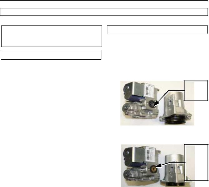
GAS ORIFICE
The SUF 199 and 250 models do not have a natural gas orifice. A .230” orifice is used on LP gas models.
Venturi
Gasket
w/o orifice
Gas Control Without Orifice
Natural Gas
Venturi Gasket w/ LP Gas Orifice (.230” Brass)
Gas Control with .230” LP Orifice
A supply gas pressure |
regulator |
(service regulator) must be installed on |
|
the gas supply line within 10' (305 cm) |
|
of the unit. |
|
|
|
State Water Heaters – Technical Training Department 6 |
Ashland City, Tennessee © 2009 |
Servicing should only be performed by a Qualified Service Agent |
198152-002 |
ULTRAFORCE COMMERCIAL GAS WATER HEATER SUF 120 thru 400 SERVICE HANDBOOK
INSTALLATION QUICK TIPS - SUF 300, 400 GAS PRESSURE
ADJUSTMENT PROCEDURE:
GAS PRESSURE
SUF 300,400,
A minimum dynamic gas supply pressure of 5.2" w.c. (1.29 kPa) for Natural Gas and 11" w.c. (2.74 kPa) for LP Gas is required before
making any adjustment to the gas control pressure regulator. Attempts to adjust the regulator during periods of low gas supply pressure could result in over firing of the water heater when the gas supply pressure returns to normal.
1.Check gas line pressure with a manometer, adjust the gas supply line pressure Gas Pressure table on page 4.
2.Check manifold pressure using a pressure gauge (manometer) connected to the manifold pressure tap on the gas control valve, If full rate adjustment is required, remove cover screw from
top of the gas control valve. Using a small screwdriver, turn adjusting screw clockwise to increase or counter clockwise to decrease gas pressure to obtain 4.0" w.c. (0.996 kPa) for Natural Gas and 10" w.c. (2.49kPa) for LP gas.
3.Cycle the burner on and off several times to check its operation.
4.Check the operation of the limit and operating controls.
5.Check the vent system seams and joints and
ensure that there is no discharge of flue products into the room.
6. Check the input rate as shown on page 5.
HIGH ALTITUDE ADJUSTMENT SUF 300,400,
For high altitude adjustments, contact the help line on the front of the water heater or contact help@statewaterheaters.com .
State Water Heaters – Technical Training Department 7 |
Ashland City, Tennessee © 2009 |
Servicing should only be performed by a Qualified Service Agent |
198152-002 |
ULTRAFORCE COMMERCIAL GAS WATER HEATER
SUF 120 thru 400 SERVICE HANDBOOK
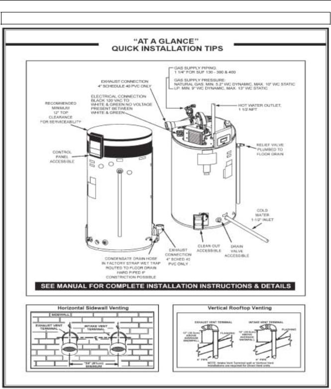
INSTALLATION TIPS - SUF 300, 400
State Water Heaters – Technical Training Department 8 |
Ashland City, Tennessee © 2009 |
Servicing should only be performed by a Qualified Service Agent |
198152-002 |

ULTRAFORCE COMMERCIAL GAS WATER HEATER
SUF 120 thru 400 SERVICE HANDBOOK
VENTING TABLES SUF 120 – 250
Maximum equivalent feet of intake and vent pipe using 3” PVC is 50 feet (15.2m). Equivalent feet must include any 90° elbows (two 45° elbows equal one 90° elbow). Three inch diameter 90° elbows are equivalent to 5' (1.5m) of pipe.
Maximum equivalent feet of intake and vent pipe using 4” PVC is 120 feet (36.6m).
Equivalent feet must include any 90° elbows (two 45° elbows equal one 90° elbow). Four inch diameter 90° elbows are equivalent to 5' (1.5m) of pipe.
Vent Length Table Equivalent Feet (Meters) 120 through 250
Number of 90° |
3" Minimum |
3" Maximum |
4"Maximum |
Elbows |
Pipe (Ft./M.) |
Pipe (Ft./M.) |
Pipe (Ft./M.) |
|
|
|
|
ONE (1) |
7/2.1 |
45/13.7 |
115/35 |
|
|
|
|
TWO (2) |
7/2.1 |
40/12.2 |
110/33.5 |
|
|
|
|
THREE (3) |
7/2.1 |
35/10.7 |
105/32 |
|
|
|
|
FOUR (4) |
7/2.1 |
30/9.1 |
100/30.5 |
|
|
|
|
FIVE (5) |
7/2.1 |
--- |
95/29 |
|
|
|
|
SIX (6) |
7/2.1 |
--- |
90/27.4 |
|
|
|
|
VENTING TABLES SUF 300,400,
Vent Length Table Equivalent Feet (Meters) 300,400,
Number of |
4" PVC |
90°Elbows |
Maximum Feet / meters of Pipe |
|
|
ONE (1) |
65' / 19.7 m |
|
|
TWO (2) |
60' / 18.2 m |
|
|
THREE (3) |
55' / 16.7 m |
|
|
FOUR (4) |
50' / 15.2 m |
|
|
FIVE (5) |
45' / 13.6 m |
|
|
SIX (6) |
40' / 12.1 m |
|
|
State Water Heaters – Technical Training Department 9 |
Ashland City, Tennessee © 2009 |
Servicing should only be performed by a Qualified Service Agent |
198152-002 |

ULTRAFORCE COMMERCIAL GAS WATER HEATER
SUF 120 thru 400 SERVICE HANDBOOK
VENTING - ALL MODELS – SINGLE PIPE POWER VENT – USING ROOM AIR
State Water Heaters – Technical Training Department 10 |
Ashland City, Tennessee © 2009 |
Servicing should only be performed by a Qualified Service Agent |
198152-002 |
ULTRAFORCE COMMERCIAL GAS WATER HEATER
SUF 120 thru 400 SERVICE HANDBOOK
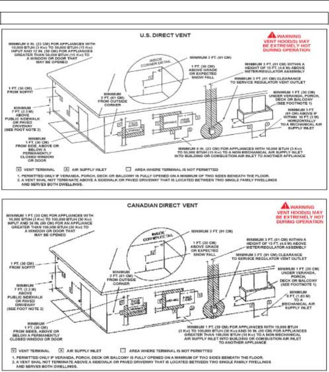
VENTING – ALL MODELS – TWO PIPE DIRECT VENT – USING OUTSIDE AIR
State Water Heaters – Technical Training Department 11 |
Ashland City, Tennessee © 2009 |
Servicing should only be performed by a Qualified Service Agent |
198152-002 |
 Loading...