


Spinning Bike Computer
Spinning® Computer
Installation and Service Manual


Table of Contents
FCC Regulatory Statements.................................................................................1
Parts List................................................................................................................2
Parts List- cont’d...................................................................................................3
Computer Window and Buttons...........................................................................4
Setup Mode............................................................................................................ 5
Setup Mode- cont’d...............................................................................................6
Setup Mode- cont’d...............................................................................................7
Sync Mode .............................................................................................................8
Re-Syncing process..............................................................................................9
Installation of Cadence Sensor – All Spinners®...............................................10
Installation Procedure V Bikes...........................................................................11
Installation Procedure Pro 5800 / 6800 / Elite 5900 ..........................................12
Installation Procedure Elite 6900 and NXT 7000...............................................13
Installing or Replacing the Batteries .................................................................14
FAQ’s and Troubleshooting...............................................................................15
FAQ’s and Troubleshooting – cont’d ................................................................16
Specifications......................................................................................................17
Marketing Statement Regarding Heart Rate......................................................18
Layout Diagram...................................................................................................19
Maintenance Checklist........................................................................................20
Spinning Education.............................................................................................21

1
1. This device complies with Part 15 of the FCC Rules. Operation is subject
to the following two conditions: (1) this device may not cause harmful
interference, and (2) this device must accept any interference received,
including interference that may cause undesired operation.
2. Changes or modifications not expressly approved by Star Trac could void
the user’s authority to operate the equipment.
FCC Regulatory Statements
2
All 727-0083 Spinning
®
Computer Kits include:
Parts List
Spinner Computer Kit Quantity Description
727-0092 1 Spinner Computer Assembly
580-0310 4 AA Panasonic Batteries
727-0093 1 Spinner Computer Mounting Bracket
140-3362 1 V2 Bracket Mounting Insert
140-3363 1 Pro Bracket Mounting Insert
727-0084 1 Spinner Computer Cadence
727-0094 1 Cadence Magnet Assembly
620-7654 1 Spinner Computer Manual
290-0039 1 M5 Allen Assembly Tool
290-0041 1 M2 Allen Assembly Tool
3
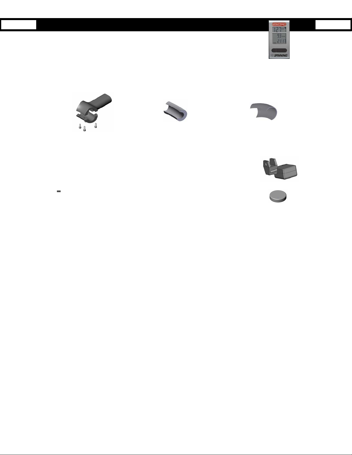
The Spinner bike computer consists of the following:
• Computer - mounts on the handlebars. This is the user interface and will show HR, RPM, kCal,
total distance and elapsed time. The computer receives signals from both the cadence unit and
a heart rate strap.
• Mounting Bracket and Inserts – mounts onto V-Bikes and Pro-Bikes. The thicker wall insert is used on the V-Bike
bracket assembly. While the thinner wall insert is used on the earlier versions of the Pro-Bike (i.e. Johnny G series).
Computer Mounting Bracket Clamp
V2 Insert (Thick Wall)
Pro Series Insert (Thin Wall)
• Cadence sensor - mounts under the left (looking from back of bike) flywheel mount. It
transmits a signal to the computer in which it calculates the user’s RPM speed.
• Magnet - mounts on the left (looking from back of bike) side of the flywheel. It activates the
Cadence sensor when it passes by the internal reed switch.
Before installing the Spinning
®
Computer, verify that all the parts needed for mounting on your bikes are included. If any of the
items are missing, call StarTrac at 800-503-1221 to order a replacement kit.
Parts List- cont’d
4
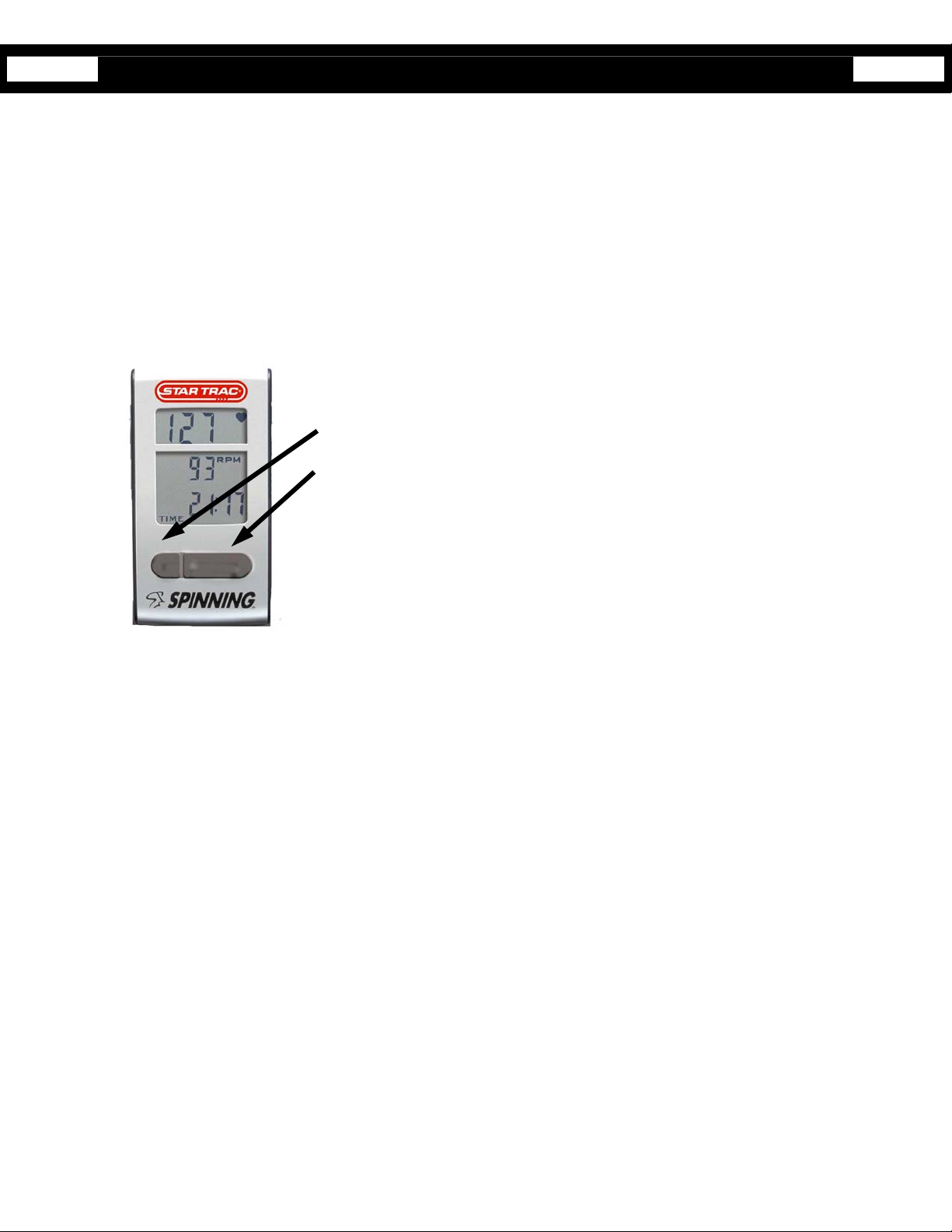
Start pedaling then press any button to turn on the spinning computer.
Pressing the Left button (LIGHT BUTTON) turns on the backlight for low lit rooms.
Pressing the Right button (TOGGLE BUTTON) displays the following information:
HR- Displays the Heart Rate of the user wearing a compatible Polar HR telemetry strap in beats per minute.
RPM- Shows the pedaling speed of the user in Revolutions Per Minute.
Total Distance- Distance measured in miles or kilometers depending on the setup selection.
Elapsed Time – The length of time in minutes from the time the computer has been activated or reset.
Buttons:
Light button – Turns on the backlight to enable viewing in low lit settings.
Toggle Button - Toggles between: Total Distance and Elapsed time.
Computer Window and Buttons
5
Setup is required only if you need to change a setting or view information.
To activate Set-Up Mode:
1. Press any button to activate computer.
2. Wave a magnet along the right side of the Spinning
®
Computer until the display window shows
all LCD segments flash.
3. Press Toggle (right) button to scroll through available set-up options.
4. Press the Light (left) button to change settings on the current display option.
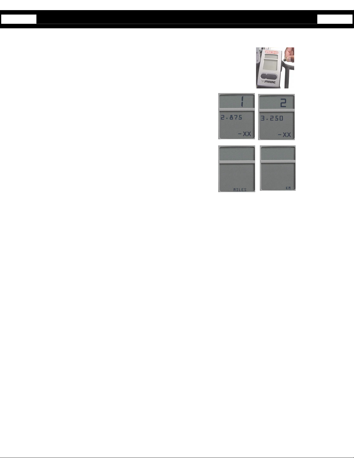
Setup mode options:
GEAR and Software Version - Gear Ratio, Select 1 (2.875) for V Bike
models or 2 (3.250) for all other models.
• Units - Miles or KM
Setup Mode

6
• BLON – (Default Back Light On) the amount of time the backlight will stay on when
the left button is pressed. NOTE: A shorter backlight time will result in longer
battery life (recommended). Select between 1 second to 60 seconds using the
Light button and press Toggle button to save.
• BLU – (Back Light Usage) Total time in minutes that the back light has been on
since the last data clearing. Press the Light button to clear data, if desired, then
press Toggle button to accept and advance to the next setting
• UH – (Usage Hours) Total operation time in hours of display since the last data
clearing. Press the Light button to clear data, if desired, then press Toggle button
to accept and advance to the next setting
• ODO – Total miles / KM
Pressing the toggle button again will exit setup mode.
Setup Mode- cont’d

7
• SON – (Summary ON Time) Number of seconds that the summary will be
displayed at the end of the workout. Options: 30, 60, 90, or 120 seconds select by
using the Light button and press Toggle button to accept.
5. To exit Set-Up mode, press the Toggle button several times until the computer returns to Workout Mode (Refer to figure in
page 4).
6. Once out of Set-Up mode and in the Workout mode, one could start monitoring the workout.
Setup Mode- cont’d
8
Syncing will need to be performed in any of the following events:
• First receiving the Spinning Computer Kit.
• Changing the 4AA batteries on the Computer.
• The original cadence and computer are no longer a pair. (i.e. when users swap
handlebars with the computer attached.)
Syncing process when first receiving the kit or installing/replacing the 4 AA batteries:
1. Remove the battery lid on the backside of the Spinning Computer and insert or replace
the 4 AA batteries.
2. Once the batteries are installed, the user will see characters on the display window which
confirms that the Workout mode has been activated.
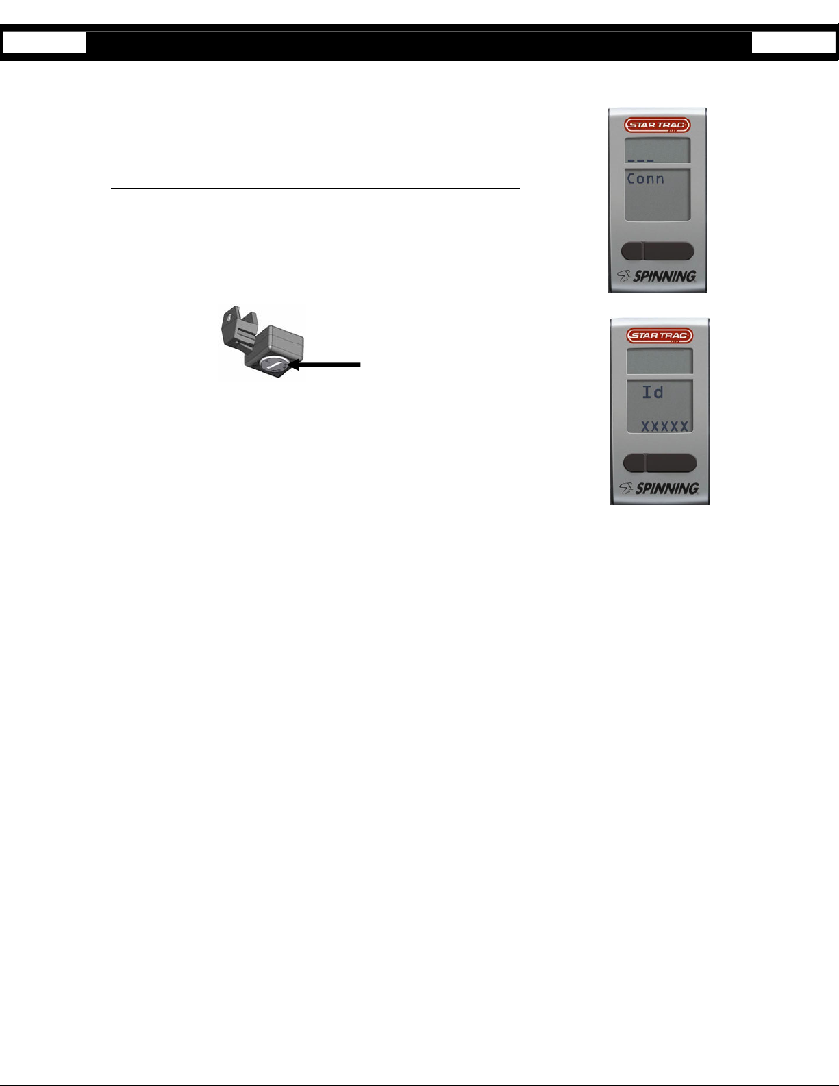
3. To begin the Syncing process, press and hold Toggle and Light buttons simultaneously.
The display should now show “Conn _ _ _” on the window.
4. Within one minute, press the Reset button on the Cadence and wave the magnet along
any of the Cadence sides.
5. Note: If Cadence and magnet are already mounted onto the Spinning bike, move
flywheel of Spinning bike to pass magnet by Cadence.
6. Once the magnet passes by the Cadence (may have to pass magnet by cadence several
times), the syncing process will be confirmed when a random ID is displayed “Id xxxxx”
(e.g. Id 45896)
7. Accept ID by pressing the Toggle button.
8. Once the Syncing process is done, the display should start showing the Workout mode.
Sync Mode
Press Reset Button
 Loading...