


Spinner® Bike
Installation Instructions
NXT 7000
ELITE 6900 |
PRO 6800 |
Page 1 of 9Star Trac Product Support 800-503-1221
Installation Instructions
SPIN BIKE ASSEMBLY AND SETUP
Use the following procedures to unpack and assemble your STAR TRAC SPINNER ® BIKE.
Prepare the area that you will be unpacking and assembling the bike to be free from debris that may cause damage. Observe all safety precautions and care while unpacking and assembling the bike.
UNPACKING
Open the shipping carton, carefully remove all parts from the shipping carton and foam inserts, inspect all packaging material for parts or screws and verify that the following parts are included in your shipment:
NXT Parts List
Description |
Qty. |
Description |
Qty. |
Handlebar Post |
1 |
M10x1.5, 55mm Button Head Screw |
4 |
Handlebar |
1 |
M10x1.5, 65mm Button Head Screw |
4 |
M8x1.25, 16mm Flat Head Screw |
2 |
M10x1.5 Nyloc Hex Nut |
8 |
M8x1.25, 16mm Socket Set Screw |
1 |
10mm Washer, Flat |
16 |
Seat Post |
1 |
Wrench Hex, 5mm |
1 |
Seat Slider Assy, with Saddle |
1 |
Wrench Hex, 4mm |
1 |
Pedal set |
1 set |
Multi Wrench |
1 |
Front Leg Assy. With Transport Wheels |
1 |
Spare Parts Kit (USA Only) |
1 Kit |
Rear Leg Assy. |
1 |
|
|
|
|
|
|
Pro/Elite Parts List |
|
|
|
Description |
Qty. |
Description |
Qty. |
Handlebar Assy. |
1 |
M10x1.5, 55mm Flat Head Screw |
4 |
Seat Post |
1 |
M10x1.5 Nut |
4 |
Seat Slider Assy, with Saddle |
1 |
10mm Washer, Flat |
4 |
Pedal Set |
1 set |
Wrench Hex, 5mm |
1 |
Front Leg Assy. With Transport Wheels |
1 |
Wrench Hex, 4mm |
1 |
Rear Leg Assy. |
1 |
Multi Wrench |
1 |
|
|
Spare Parts Kit (USA Only) |
1 Kit |
Spare Parts Kit- Save the box of spare parts in a safe place so you have service parts when needed in the future. The spare parts kit contains a spare saddle, brake pad and pedals straps. These items are not included in the parts warranty.
NOTE: If you are missing any of the parts listed above, inspect the packing material and the box for items that may have been overlooked.
If parts are missing, or if you have any product questions, please call Star Trac’s Service Department at (800) 503-1221, please have your Spinner® serial number ready.
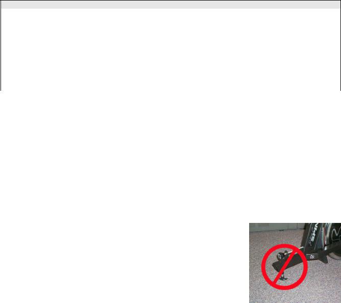
CAUTION: Damage to the bike during assembly is not covered as part of the limited Star Trac warranty. Take care not to drop or lean the bike on the handle bar pop pin. Carefully stand the bike up in the normal upright position on a stable surface so it will not tip over during assembly.
Page 1 of 9
Page 2 of 9Star Trac Product Support 800-503-1221
Assembly
Following these steps in order will minimize the build time and ensure proper assembly.
Note: Not all of the following procedures are performed on all models; Spinner ® Pro, Elite and NXT.
If the procedure is particular to that model only it will be noted as follows: (NXT Only) or (Pro/Elite Only) or (NXT/Elite Only)
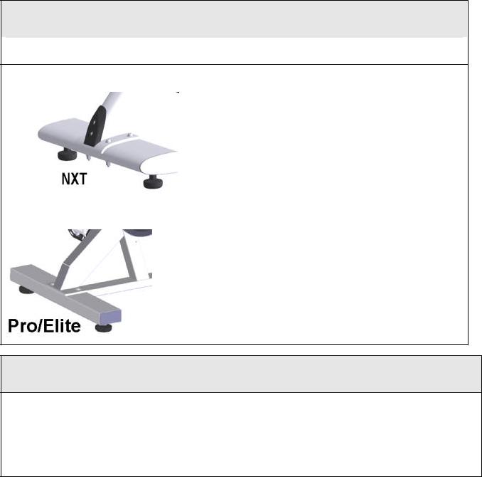
Installation of the Rear Leg Assembly
Lift up the rear of the bike frame and place the rear leg assembly in position under the frame, aligning the holes in the leg with the holes in the frame.
|
NXT Only |
1. |
Position the leg so the thicker end faces toward the front |
|
|
|
|
|
of the bike |
|
|
|
2. |
Using the 5mm hex wrench and a 13mm combination |
|
|
|
|
wrench insert 2- M10X55mm (rear-most holes) and 2- |
|
|
|
|
M10X65mm (front-most holes) button head screws, nuts |
|
|
|
|
and washers (under bolt head and nut), to secure the |
|
|
|
|
rear leg assembly to the frame. The nut should be on |
|
|
|
|
the bottom of the bike and the head of the screw on the |
|
|
|
|
top of the bike. |
|
|
|
3. |
Tighten all hardware securely using a torque wrench to |
|
|
|
|
85 Inch Pounds |
|
|
|
|
|
|
Pro & Elite Only |
1. |
Lift up the rear of the bike frame and place the rear leg |
|
|
|
|
|
assembly in position under the frame, aligning the holes |
|
|
|
|
in the leg with the holes in the frame. |
|
|
|
2. |
Using the 5mm hex wrench and a 13mm combination |
|
|
|
|
wrench insert 2- M10X55mm flat head screws, nuts and |
washers to secure the rear leg assembly to the frame. The nut should be on the bottom of the bike and the head of the screw on the top of the bike.
Tighten all screws/nuts securely using a torque wrench to 85 Inch Pounds
Installation of the Front Leg Assembly
NOTE: The front foot assembly has wheels attached to the front edge. Be sure the wheels face forward when installing the front leg assembly.
Stand the bike frame upright and gently tip the front of the bike up and position the front foot under the frame, with the wheels facing forward.
Attach the front foot assembly to the frame, aligning the holes in the foot with the holes in the frame.
Page 2 of 9
 Loading...