


S-RBX
620-7992 Rev 001
S
TAR
T
RAC
F
ITNESS™
P
ERSONAL
V
IEWING
S
CREEN
U
SER'S
M
ANUAL—
S-S
ERIES
STAR TRAC
14410 Myford Road
Irvine, CA 926060 USA
S-UBx, S-RBx, S-TBTx
S-TRx, S-TRc

2
620-7992 Rev 001

3
620-7992 Rev 001
T
ABLE OF
C
ONTENTS
Introduction .............................................................................................................................................. 4
Before You Get Started ............................................................................................................................ 5
Warnings and Cautions ........................................................................................................................... 6
Important Safety Precautions .................................................................................................................. 7
Unpacking Your Personal Viewing Screen ............................................................................................. 8
Installing your STAR TRAC Personal Viewing Screen .........................................................................10
S-UBx, S-RBx, and S-TBTx ...........................................................................................................10
S-TRc and STRx ............................................................................................................................13
Installing the Power Supply on the S-TRx .......................................................................................15
Setting Up your NTSC / ATSC Personal Viewing Screen ......................................................................17
Basic Operations ...........................................................................................................................17
Adjusting Picture Menu Options .....................................................................................................18
Adjusting Audio Menu Options .......................................................................................................19
Adjusting Setup Menu Options .......................................................................................................21
Adjusting Channel Menu Options ...................................................................................................25
Setting Up your PAL / SECAM Personal Viewing Screen .....................................................................27
Basic Operations ...........................................................................................................................27
Adjusting Picture Menu Options .....................................................................................................28
Adjusting Sound Menu Options ......................................................................................................29
Adjusting Time Menu Options ........................................................................................................30
Adjusting System Options Menu ....................................................................................................32
Adjusting Lock Menu Options ........................................................................................................33
Adjusting Channel Menu Options ...................................................................................................35
FAQ’s and Troubleshooting ...................................................................................................................38
Cleaning the PVS ..........................................................................................................................38
Troubleshooting .............................................................................................................................38
Headphone Jack Replacement ......................................................................................................40
Regulatory Information ...........................................................................................................................41
Copyright 2010. Star Trac by Unisen, Inc. All rights reserved, including those to reproduce this book or parts thereof in any form without first obtaining
written permission from Star Trac.
Every effort has been made to keep this information current; however, periodically, changes are made to the information herein, and these changes will
be incorporated into new editions of this publication. All product names and logos are trademarks of their respective owners. Printed in the USA.

4
620-7992 Rev 001
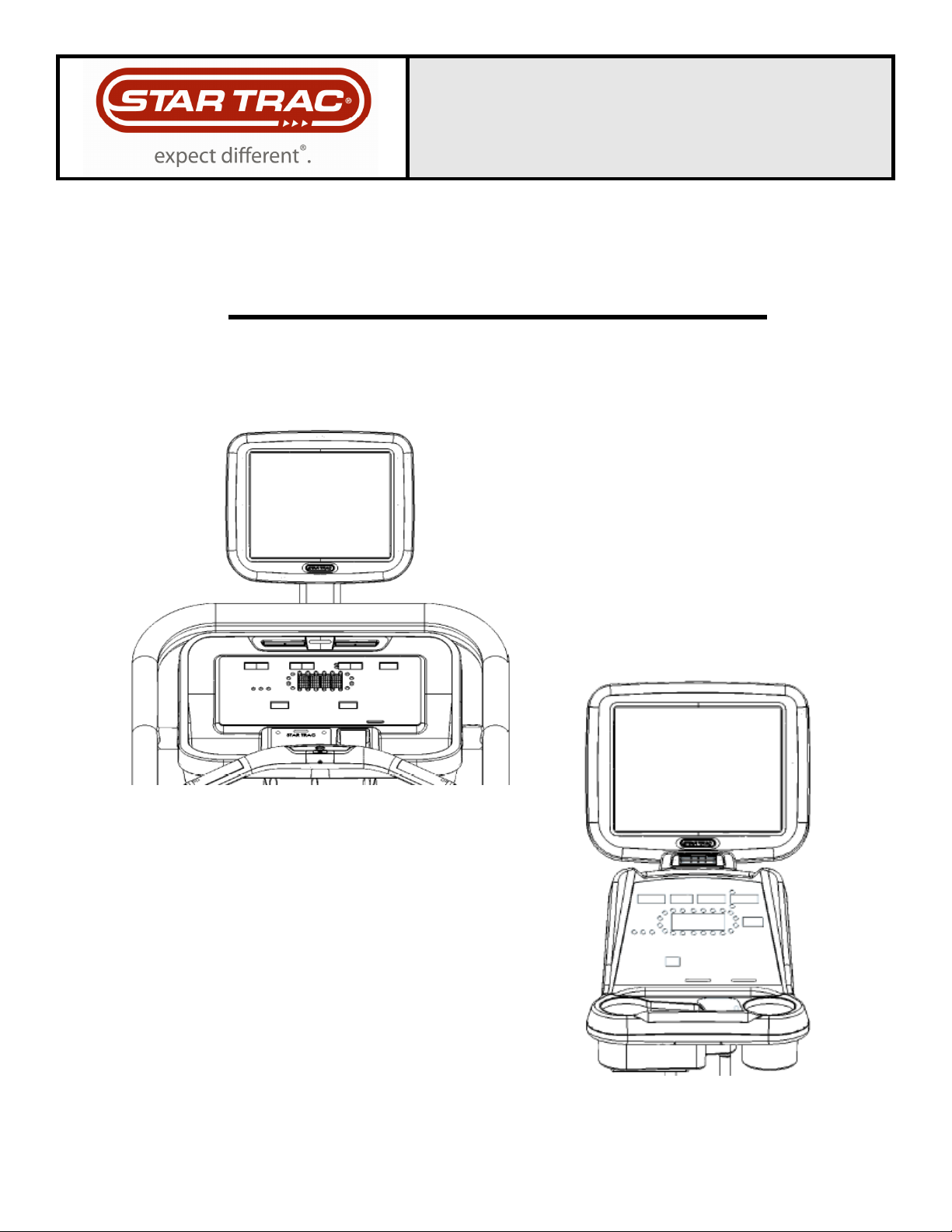
Thank you for adding the STAR TRAC PERSONAL VIEWING SCREEN (PVS) to your Star Trac
Purchase. The Personal Viewing Screen has been designed to provide the user with the most re-
warding experience based upon the carefully planned features it possesses. The design elements
of this Personal Viewing Screen will provide you with a comfortable, intuitive, safe and reliable ex-
perience, guiding you to a habit-forming lifestyle. Star Trac's mission is to provide products to mold
lifelong habits for health and fitness.
ABOUT THIS MANUAL
This manual is applicable to the STAR TRAC S-UBx UPRIGHT BIKE, S-RBx RECUMBENT BIKE,
S-TBTx TOTAL BODY TRAINER, and the S-TR TREADMILLS The manual is divided into nine sec-
tions, as follows:
Introduction
Provides an overview of each section within the manual.
Before You Get Started
Provides guidelines to help you have a successful installation.
Warnings and Cautions
Helpful safety tips to keep you out of harms way.
Important Safety Precautions
Provides important safety tips to keep you out of harms way.
Unpacking your Personal Viewing Screen
Provides a description of what you will find in your PVS kit.
Installing Your STAR TRAC Personal Viewing Screen (PVS)
Provides a step-by-step instruction set for installing your PVS on the S-UBx, S-RBx, S-TBTx
and S-TR.
Setting Up Your STAR TRAC Personal Viewing Screen (PVS)
Provides step-by-step instruction set for configuring your PVS with either the NTSC/ATSC or
PAL/SECAM screen.
FAQ’s and Troubleshooting
Frequently asked questions and troubleshooting methods to help solve problems that may
occur with your PVS.
Regulatory Information
Provides regulatory information for the Star Trac Personal Viewing Screen.
I
NTRODUCTION

5
620-7992 Rev 001
B
EFORE
Y
OU
G
ET
S
TARTED
C
HECK
F
ACILITIES
P
REPAREDNESS
For a proper installation, please read this guide thoroughly and follow the instructions. Star Trac’s
goal is to help you have a successful and reliable installation, for this reason we have come up with
some helpful tips and check list to accomplish this goal.
E
QUIPMENT
L
AYOUT
Check to see that the equipment you will be adding the PVS to are placed where they will be used. It
is recommended that you follow your installation guides for each one of your Star Trac pieces of
equipment in making sure that there is ample space around them to ensure a safe and enjoyable
experience.
I
NPUT
S
IGNAL
In the world of entertainment today you have many choices. Star Trac recommends you know what
type of video signal (cable, analogue, digital, satellite, antenna) is in the club facility and if it has a
good signal. Don’t forget every installation is different. Check to see that you have a coaxial cable
connection at each location where a PVS will be installed.
C
ABLING
When Radio Frequency signals travel through cabling the signal will degrade over distance. Connec-
tors may degrade the signal as well. Check each output before connecting to your PVS and make
sure you have a clean strong signal to ensure an enjoyable experience. The Star Trac PVS requires
a minimum signal strength of 45dBmV for analogue channels, and 40% for digital channels. Your
club may require signal amplifiers to achieve a good strong signal. Star Trac recommends you use a
qualified installer for your Audio Visual needs.
E
LECTRICAL
R
ECEPTACLES
The Personal Viewing Screen requires a plug-in 60 watt power supply to operate (
included in each kit
with the exception of the S-TRc
). Check with your club facility to ensure ample electrical receptacles
are placed next to the equipment for a safe and proper install. Check with your contractor to make
sure you have enough power.
6
620-7992 Rev 001
W
ARNINGS
A
ND
C
AUTIONS
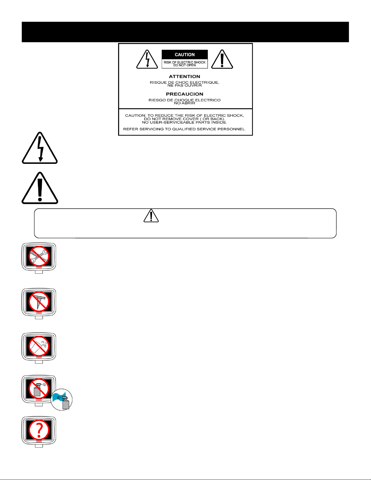
This lighting flash with arrowhead symbol, within an equilateral triangle, is intended to alert
the user to the presence of un-insulated “dangerous voltage” within the product’s enclo-
sure that may be of sufficient magnitude to constitute a risk of electric shock to persons.
This exclamation point within an equilateral triangle is intended to alert the user to the
presence of important operating and maintenance (servicing) instruction in the literature
accompanying the appliance.
WARNING:
To reduce the risk of fire or electric shock, do not expose this appliance to rain or moisture.
DO NOT disassemble the PVS.
Any unauthorized maintenance will void the warranty. Inexperienced technicians can cause
serious damage, electric shock, and other hazards.
Contact your dealer or an experienced technician for repair.
DO NOT place sharp tools such as a pin or other metallic object near the display.
May result in scratching the surface of the monitor as well as the frame.
Keep your monitor away from liquid or a humid place.
May cause electric shock and damage the display.
When strange sound or smoke occurs, be sure to unplug your power cord.
These problems can cause a serious electric shock and other hazards.
DO NOT spray any fluid directly on the surface of the monitor.
Spray the cleaner fluid on a soft cloth to wipe the surface of the monitor.

7
620-7992 Rev 001
I
MPORTANT
S
AFETY
P
RECAUTIONS
Electrical energy can perform many useful functions, but it can also cause personal injuries and property
damage if improperly handled. This product has been engineered and manufactured with the highest prior-
ity on safety. But IMPROPER USE CAN RESULT IN POTENTIAL ELECTRICAL SHOCK OR FIRE HAZ-
ARD. In order to prevent potential danger, please read the following instructions when installing, operating
and cleaning the product. To ensure your safety and prolong the service life of your new product, please
read the following precautions carefully before using the product.
1. Read these instructions---All operating instructions must be read and understood before the product is
operated.
2. Keep these instructions---These safety and operating instructions must be kept in a safe place for fu-
ture reference.
3. Heed all warnings---All warnings on the product and in the instructions must be observed closely.
4. Follow all instructions---All operating instructions must be followed.
5. Power source---This product is intended to be supplied by a listed power supply indicated on the mark-
ing label. If you are not sure of the type of power supply to your home, consult your product dealer or
local power company. For added protection for this product during a lightning storm, or when it is left
unattended and unused for long periods of time, unplug it from the wall outlet and disconnect the cable
system.
6. Power cord protection---Protect the power cord from being walked on or pinched particularly at plugs,
convenience receptacles, and the point where they exit from the apparatus.
Note: where the mains plug or an appliance coupler is used as the disconnect device, the disconnect
device shall remain readily operable.
7. Overloading---Do not overload wall outlets, extension cords, or convenience receptacles on other
equipment as this can result in a risk of fire or electric shock.
8. Replacement parts---In case the product needs replacement parts, make sure that the service person
replaces parts specified by the manufacturer, or those with the same characteristics and performance
as the original parts. Use of unauthorized parts can result in fire, electric shock and/or other dangers.
9. Safety checks---Upon completion of service or repair work, request the service technician to perform
safety checks to ensure that the product is in proper operating condition.
10. Clean only with damp cloth---Unplug this product from the wall outlet before cleaning. Do not use liq-
uid cleaners or aerosol cleaners. Use a damp cloth for cleaning.
11. Panel protection---The display panel used in this product is made of glass. Therefore, it can break
when the product is dropped or impacted upon by other objects. Be careful not to be injured by broken
glass pieces in case the display panel breaks.
12. Pixel defect---The display panel is a very high technology product, giving you finely detailed pictures.
Occasionally, a few non-active pixels may appear on the screen as a fixed point of blue, green or red.
Please note that this does not affect the performance of your product.
Warning:
To prevent the spread of fire, keep candles or other open flames
away from this product at all times.

8
620-7992 Rev 001
U
NPACKING
Y
OUR
P
ERSONAL
V
IEWING
S
CREEN
Inspect the shipping box for any parts that may be missing BEFORE discarding the box. Items can shift dur-
ing transportation, and may be accidentally discarded with the box. If any parts are missing, please contact
Star Trac Product Support at 800-503-1221. Have the serial number of the PVS, and a list of the missing
parts ready so they may be shipped to you. The Personal Viewing Screen is shipped in one box separate
from your exercise equipment.
PVS kits are available in two different signal formats; NTSC/ATSC (typically US, Japan) and PAL/SECAM
(typically Europe, Middle East), make sure the kit you have is appropriate for the country of the club facility.
The following items will be in the box:
NTSC/ATSC Kit (US, Japan)
•
PVS assembly with mounting bracket, cables, and display cap with grommet
(There are 5 cables in the neck)
•
Center console keypad assembly
•
Entertainment headphone jack and Mount
•
Hardware tool kit, including:
•
(3) M8 buttonhead screws
•
(3) 5/16 lock washer
•
(2) 5” tie straps
•
5MM hex Allen key.
•
60w Power Supply
(NOT INCLUDED IN THE S-TRc KIT)
•
Power cord, CEE 7/7
(NOT INCLUDED IN THE S-TRi KIT)
•
Power cord, Nema 6-15
(NOT INCLUDED IN THE S-TRi KIT)
•
Power cord, BS 1363
(NOT INCLUDED IN THE S-TRi KIT)
•
Owners manual
•
Warranty card.

9
620-7992 Rev 001
PAL/SECAM Kit (Europe, Middle East)
•
PVS assembly with mounting bracket, cables, and display cap with
grommet (There are 5 cables in the neck)
•
Center console keypad assembly
•
Entertainment headphone jack and mount
•
Hardware tool kit, including:
•
(3) M8 buttonhead screws
•
(3) 5/16 lock washer
•
(2) 5” tie straps
•
F-type to PAL/SECAM coaxial adapter
•
5MM hex Allen key.
•
60w power supply
(NOT INCLUDED IN THE S-TRc KIT)
•
Power cord, CEE 7/7
(NOT INCLUDED IN THE S-TRi KIT)
•
Power cord, Nema 6-15
(NOT INCLUDED IN THE S-TRi KIT)
•
Power cord, BS 1363
(NOT INCLUDED IN THE S-TRi KIT)
•
Owners manual
•
Warranty card.
Required Tool for Installation
•
5MM hex Allen key
•
#2 Phillips screwdriver
•
Wire cutters
(Not Included)
•
Pliers
(Not Included)
•
Step stool
(Not Included)
•
Flat Head screw driver
(Not Included)
10
620-7992 Rev 001
The Star Trac Personal Viewing Screen is different for each of your Star Trac S-Series Cardio products.
Make sure you have the proper kit for the S-Series product you are installing. The S-UBx, S-RBx and S-TBTx
will follow the same basic steps for installation. For the S-TR turn to appropriate section of this manual.
I
NSTALLING
Y
OUR PVS
O
N
T
HE S-UBx, S-RBx
A
ND S-TBTx
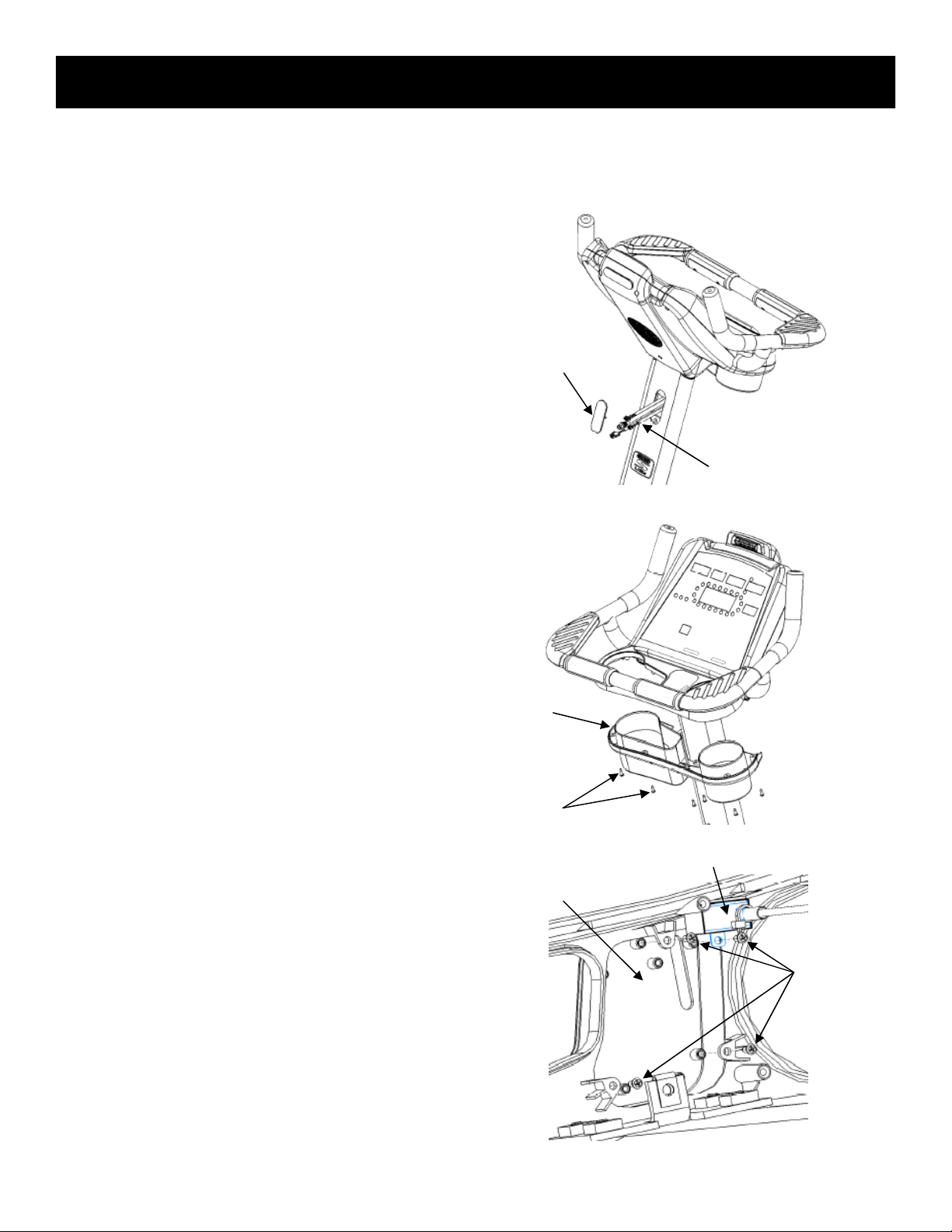
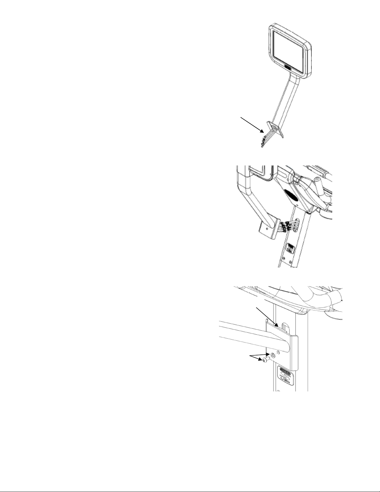
STEP 1.
Using a flat head screwdriver, remove the TV
HOLE CAP, from the back of the display. (You
will no longer need this cap and, if desired, you
can store it away for any possible future use).
Pull out the (4) cables from the hole.
Note: three (3) cables are attached with the TV hole
cap with a cable tie, and the coaxial cable is a loose
cable.
STEP 2.
Using a #2 Phillip screwdriver, remove the (9)
screws that hold the display’ bottom cover plas-
tics in place. Retain the screws for later use.
STEP 3.
Using a #2 Phillip screwdriver, remove the (4)
screws that hold the center console at the bot-
tom side of the cover (Three for center console
and one for Wireless HR receiver).
TV Hole Cap
Cable Set
Bottom Cover
(9) Screws
Center Console
Screws
Wireless HR Receiver
11
620-7992 Rev 001
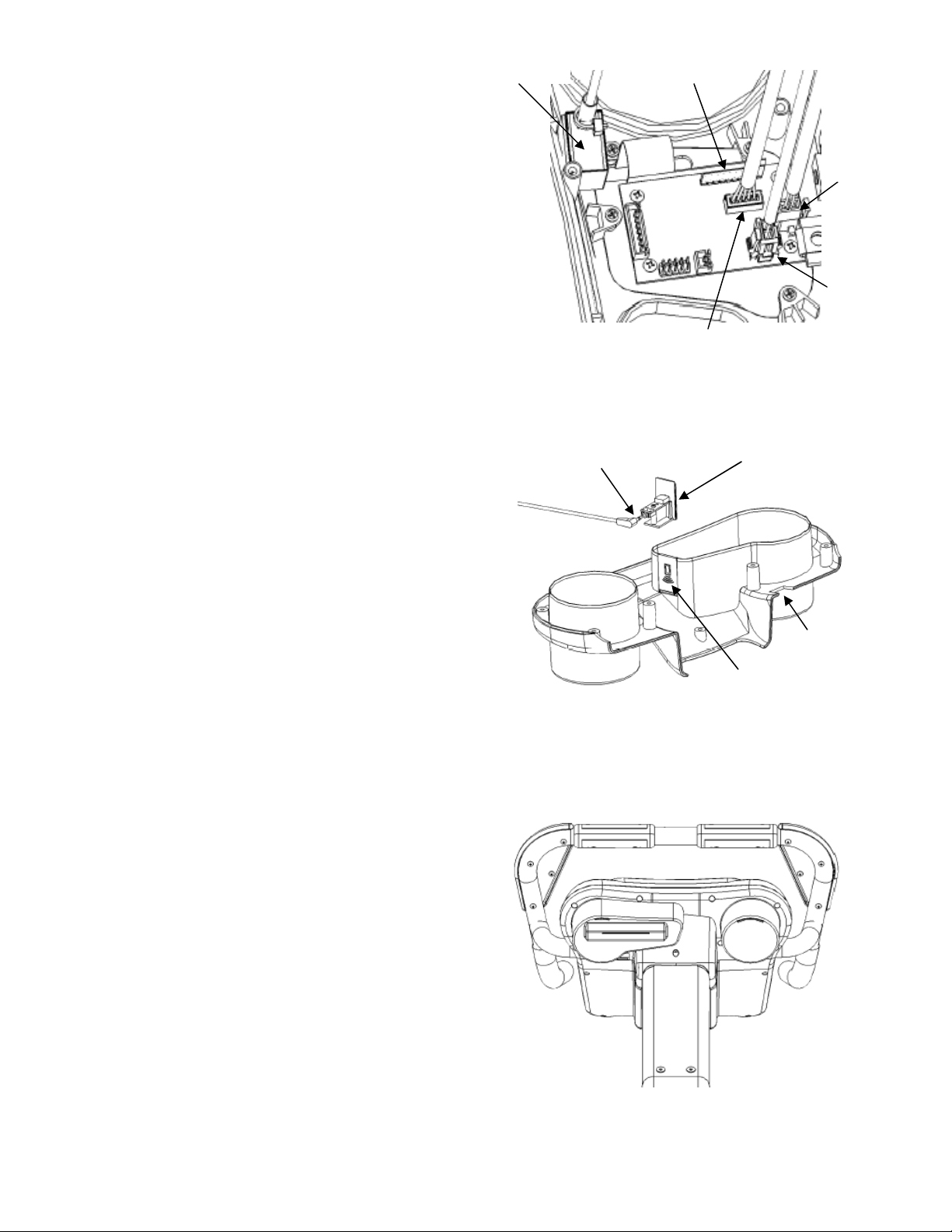
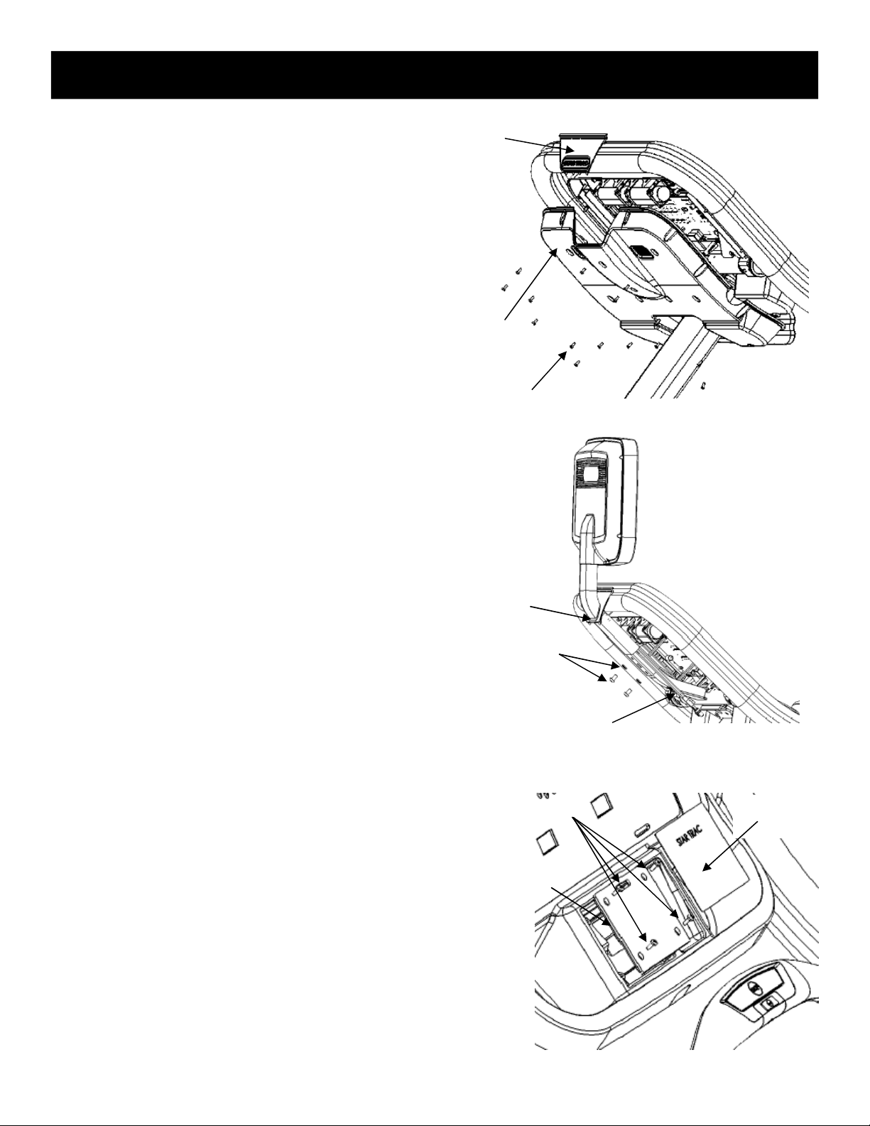
STEP 4.
Replace the TV control pad:
•Using a #2 Phillip screwdriver, fasten the TV con-
trol pad with the (3) screws and install the wire-
less HR receiver back to the same location.
•
Plug in the TV keypad connector into JP5
•
Plug in the interface control connector into
JP4
•
Plug in the power-in connector into JP7
•
Plug in the power-out connector into JP6
STEP 5.
Using a pair of pliers, remove the IR-Reader
plastics from the bottom cover, and replace it
with the headphone adaptor. And then, plug in
the 90° angle headphone plug as shown.
STEP 6.
Install the bottom cover back and secure using
the (9) screws you saved from earlier step.
Polar Receiver
TV Keypad Cable
Interface Control
(5-Contacts)
Power-out
Power-in
Bottom Cover
IR-Reader
Headphone Adaptor
Headphone Plug
12
620-7992 Rev 001
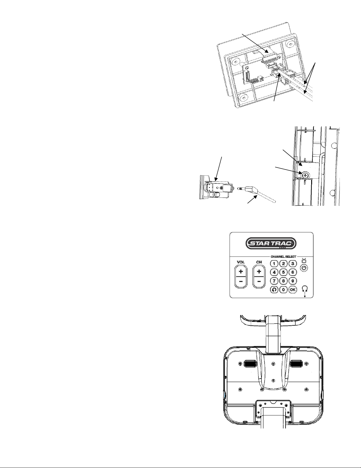
STEP 7.
Unpack the TV kit from the PVS package and
pull out the (4) cables from the square hole on
the neck bracket.
STEP 8.
Connect the (4) cables on the TV Kit with the
(4) cables on the unit as shown:
•
Antenna cable (coaxial)
•
Power cable (2-Contacts)
•
Interface cable (5-Contacts)
•
Headphone cable (3-Contacts)
Insert the connecters and wires through the
neck hole into the tube.
STEP 9.
Insert the TV bracket tab into the cable hole on
the neck, and push in and upwards to align
hole.
Install the screw and washer, and use the 5mm
Allen wrench to tighten the screw.
(4) Cables
Tab
Screw & Washer
This completes the installation of the Personal Viewing Screen. Now it is time to set it up. Turn
to the appropriate section for your Personal Viewing Screen.
Note:
The shown PVS assembly procedures are for S-UBx bike. The PVS assembly procedures for S-RBx and S-TBTx are
the same as the S-UBx bike, however the brackets are different.
13
620-7992 Rev 001
STEP 3.
Now, replace the TV keypad on the front dis-
play. Carefully remove the label of the center
console with a flat screw driver. And then, re-
move the (4) screws that hold the center con-
sole in place. Retain all the screws for later
use.
STEP 1.
Using a #2 Phillips screwdriver, remove the (19)
screws that hold the back cover of the display.
Next, remove the back cover and the upper cap
cover with “Star Trac Logo” on it (You will no
longer need this cap cover and, if desired, you
can store it away for any possible future use).
Retain all the screws for later use.
STEP 2.
Take the PVS from its package and remove the
bubble wrap. Insert the PVS into the rectangle
tube on the back of the treadmill. Adjust the
new cap into place, (make sure it is below
handrail), then fasten with (2) M8 screws and
(2) washers.
Note: Keep all (4) cables on the right side.
I
NSTALLING
Y
OUR PVS
O
N
T
HE
S
-TRc
A
ND
S
-TRx
Screws
Cap
Back
Cover
(4) Screws
CENTER
CONSOLE
LABEL, CENTER
CONSOLE
Cap
(4) Cables
Screws and
washers
14
620-7992 Rev 001
STEP 4.
Insert the keypad cable into the oblong hole of the
console, and plug it into the board (as shown on
the right figure).
Plug in the Interface remote control cable (5-
contacts), power-in cable (2-contacts), and power
-out cable (2-contacts) to each header as shown
on the right figure.
STEP 5.
Using a #2 Phillips screwdriver, remove the screw
that holds in the blank headphone jack cap at the
lower front of the display. Retain the screw (You
will no longer need the cap and, if desired, you
can store it away for any possible future use).
Now take the Entertainment headphone jack from
the PVS hardware kit, and plug in the headphone
cable to the jack. Use the previously retained
screw to reinstall the headphone jack. Tighten
snugly.
STEP 6.
Install the center console back to the front display
cover and secure with the (4) screws removed in
step 3.
Remove the protective paper on the back side of
the keypad, and attach it to the console plastic.
Be sure to make good alignment between the
console plastic and keypad, also Make sure there
are no air bubbles trapped between the keypad
and the console plastic.
Interface control
cable (5-contacts)
Power-in and
power-out cables
(2-contacts)
Keypad cable
Blank Cap
Screw
Headphone
Jack
Headphone
Cable
STEP 7.
Replace the top back cover. Using a #2 Phillips
screwdriver, insert (19) screws, retained from ear-
lier step, into the plastic cover. Do not tighten
screws yet.
Check the cap with the neck and grommet. Make
sure the cap is flush with the top back plastic, and
adjust if necessary. Tighten screws to secure the
back plastics.
This completes the installation of the PVS on the S-TRc treadmill.
If
you have an S-TRx continue to next section to install the power supply
.
 Loading...