


STAR TRAC
14410 Myford Road
Irvine, CA 926060 USA
WORK INSTRUCTIONS,
E-TBT / E-TBTe INSTALLATION

GENERAL
Before using this product, it is essential to read ALL installation Instructions and this ENTIRE operations manual; the manual describes equipment setup and instructs members on how to use it correctly and safely.
TOOLS REQUIRED
1.Phillips screwdriver, #2 (Included)
2.Hex (Allen) key, 3/16 (Included)
3.Hex (Allen) key, 16” (Included)
4.Hex (Allen) key, 5MM (Included)
5.Torque wrench (not included)
FACTORY CERTIFIED INSTALLER
If you are a Factory Certified Installer you must:
•Adhere to all torque and assembly specifications.
•Use a CALIBRATED TORQUE WRENCH with the necessary hex key sockets
•NOT USE a powered drill, powered driver or powered impact tool for any part of the assembly.
•Complete the assembly checklist is completed on each Star Trac product.
•Complete the final programming, functional and cosmetic checklists for each Star Trac product.
Copyright 2008. Star Trac by Unisen, Inc. Star Trac Fitness, Star Trac®, and the Star Trac Logo are registered trademarks of Unisen Inc. All rights reserved, including those to reproduce this book or parts thereof in any form without first obtaining written permission from Star Trac.
iPod® is a registered trademark of Apple, Inc.
MYE® is a registered trademark of MYE Entertainment LLC.
Every effort has been made to keep this information current; however, periodically, changes are made to the information herein, and these changes will be incorporated into new editions of this publication. All product names and logos are trademarks of their respective owners. Printed in the USA.
3 |
620-7921 Rev A |
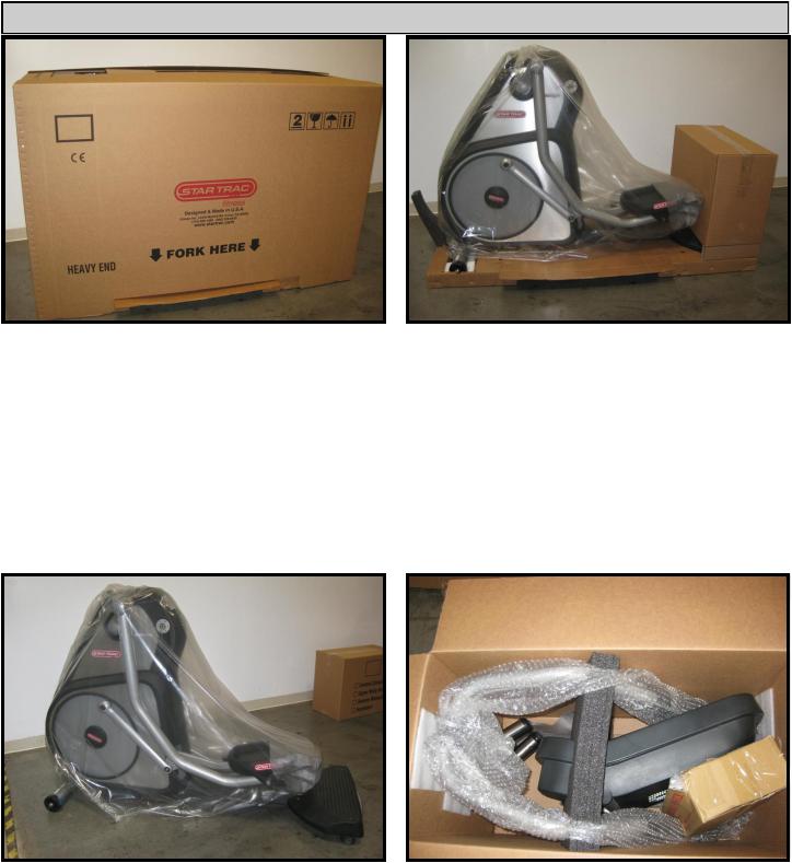
UNPACKING INSTRUCTIONS
Step 1.
Lay the box with heavy end facing down in the area where it is going to be assembled. Cut and remove packaging straps then open and remove the top cover.
Step 2.
Lift and remove the box from the pallet base.
Step 3.
Lift the unit off of the pallet base, then remove all packaging materials.
4
Step 4.
Open the display assembly box and carefully remove its content.
620-7921 Rev A
Step 5.
Remove remaining packaging materials and lay all components on the floor.
Step 6. |
1 |
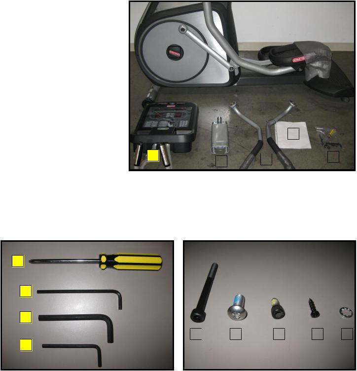
Verify the following components are included in the package:
1.TBT frame.
2.Display console assembly.
3.Upper neck.
4.Left and right upper body arms.
5.Owner’s manual, installation manual and warranty registration card.
6.Hardware kit.
2
1
2
3
4
Step 7.
Verify the following tools are included in the kit:
Item |
Description |
QTY |
|
|
|
1 |
#2 Phillips screwdriver |
1 |
|
|
|
2 |
3/16 Hex (Allen) key |
1 |
|
|
|
3 |
5/16” Hex (Allen) key |
1 |
|
|
|
4 |
5mm Hex (Allen) key |
1 |
|
|
|
|
|
|
|
5 |
|
|
|
|
|
|
|
|
|
|
|
|
|
|
|
6 |
|
|
4 |
|
|||
3 |
|
|||||
|
|
|
|
|
||
|
|
|
|
|
|
|
1 |
|
2 |
|
3 |
|
4 |
|
5 |
Step 8.
Verify the following hardware is included in the kit:
Item |
Description |
QTY |
|
|
|
1 |
6mm x 50mm socket head cap screw |
4 |
|
|
|
2 |
5/16 - 18 x 3/4 button head screw |
2 |
|
|
|
3 |
1/4 - 20 x 1/2 socket head screw |
10 |
4 |
M4 x 0.7 x 19mm Philips head screw |
6 |
|
|
|
5 |
Washer |
4 |
|
|
|
5 |
620-7921 Rev A |
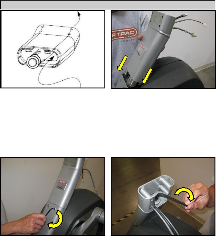
INSTALLATION INSTRUCTIONS
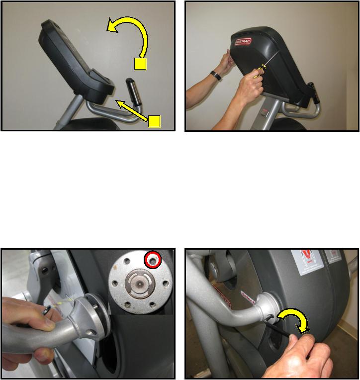
Step 1.
Route display cables up through upper half of neck through the holes provided.
Step 2.
Insert the upper half of the neck into the lower half.
Caution: Be careful not to pinch any cables between the two sections of the assembled neck.
Step 3.
Install two 5/16” - 18 X 3/4” button head screws into front neck using a 3/16” hex key. Tighten bolts to 200 in-lbs (23 N-m).
6
Step 4.
Secure the neck by tightening the 3/8-16 x 2” socket head cap screw using a 5/16” hex key. Tighten bolt to 300 in-lbs (34 N-m).
620-7921 Rev A
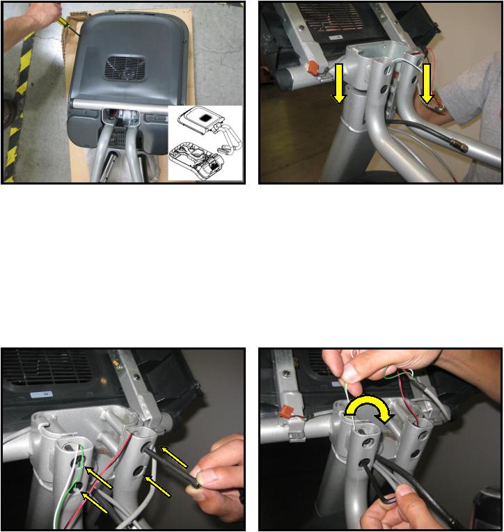
Step 5.
Using provided screwdriver, remove the M4 x 0.7 screws that hold the display assembly together, then separate the back of the display from the front.
Note: Retain the screws for later use.
Step 7.
Line up the four holes of the mounting bracket with holes of the neck, then insert four 6mm x 50mm socket head cap screws.
Step 6.
Slide the back of the display with the mounting bracket onto the upper neck of the Total Body Trainer.
Caution: Be careful not to pinch any cables between the two sections of the assembled neck
Step 8.
Using provided 5mm hex key, tighten down the screws to 240 in-lbs (27 N-m).
7 |
620-7921 Rev A |

3
2
4
1
Step 9.
Identify the four cables coming out of the neck and mounting bracket:
1.Heart rate cable
2.Main I/O cable
3.Coax cable
4.DC power cable
Note: If the unit is not equipped with Personal Viewing Screen, the coax and DC power cables should be tucked down the neck as they are part of the PVS Kit.
Step 11.
Next, plug-in the heart rate cable into the HR board connector.
Step 10.
Plug-in the 12-pin main I/O cable into the front display circuit board at J4 connector.
Step 12.
Plug back the HR ground cable into the quick disconnect tab on the display frame.
8 |
620-7921 Rev A |
2
1
Step 13.
Assemble the front and back display parts together by sliding the bottom of the front display under the 2 tabs at the base first, then pressing front display against the back cover.
Caution: Be careful not to pinch any wires.
Step 15.
Locate left side upper body arm, move to left side of the Total Body Trainer. Attach the left upper body arm to the left hub, align the pin to the unthreaded hole.
Step 14.
Using provided Phillips head screw driver, secure the front display to the back with (8) M4 x 0.7 x 19mm long Phillips head screws.
Step 16.
Install the left arm and secure with (5) 1/4-20 x 1/2 socket head screws. Tighten the screws to 240 in-lbs (27 N-m) of torque with the 3/16” hex key. Repeat for the opposite side.
9 |
620-7921 Rev A |
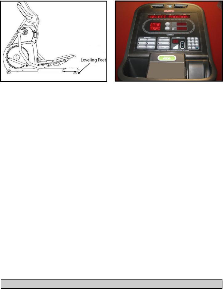
Step 17.
Place the Total Body Trainer on the floor in the position it will be used. Then adjust leveling feet to assure that the Total Body Trainer is leveled to the floor and does not rock back and forth.
Step 18.
Perform a visual inspection, and test the features and functions of the unit prior to use.
Note: Refer to the User’s Manual for other settings and instructions.
YOUHAVEHAVENOWNOWCOMPLETEDHE INSTALLATIONTHE TOTAL BODYOF YOURTRAINERTOTALINSTALLATBODY TRAINERON
10 |
620-7921 Rev A |

Use the checklist below to ensure the proper installation of the Total Body Trainer:
 1. All parts, tools and hardware in the package are accounted for.
 2. All screws are tightened and torqued down to their specified values.
 3. Upper body arms are properly mounted and secured.
 4. Upper body arms move freely, along the entire range of motion.
 5. Upper neck is properly mounted and secured.
 6. Display’s mounting bracket and back cover are properly mounted and secured.
 7. All cables and harnesses are properly plugged to their respective connectors.
 8. The front and back display plastics are properly installed and secured.
 9. Verify unit is leveled to the floor.
 10.Once powered up, all features of the unit function properly.
ATTENTION
•Star Trac recommends that the Total Body Trainers be spaced a minimum of 20.0 inches (0.5
m)apart to allow safe and easy ingress and egress. Even more importantly, there must be at least 48 inches (1.25 m) of free space behind the Total Body Trainer.
•As with any motorized equipment, the area where Total Body Trainers are located must be free of obstructions and fixtures with sharp edges to prevent injury in the event that a user trips or loses balance and falls.
For technical assistance call Star Trac Customer Service: 1 800 503 1221
11 |
620-7921 Rev A |
EMBEDDED DISPLAY CONSOLE INSTALLATION INSTRUCTIONS
|
|
2 |
|
|
|
|
|
3 |
|
1 |
|
|||
|
|
|
||
|
|
|
|
4
5
Step 1.
Remove all contents from the packaging and verify that you have the following parts:
1.Embedded display console.
2.Operation manual.
3.Tool kit.
4.Power adaptor (60W AC).
5.Power cord.
1
2 |
|
3 |
Step 2.
Verify the tool kit has the following parts:
Item |
Description |
QTY |
|
|
|
1 |
Assembly instructions |
1 |
|
|
|
2 |
Screw, Phillips Head, M4 x 19mm |
18 |
|
|
|
3 |
Washer, flat, M4 |
5 |
|
|
|
Step 3.
Be careful with the display and place it face down on top of a non-scratching surface to protect it from being damaged.
Step 4.
Remove the back cover from the embedded display assembly and place it in a safe place for later use.
12 |
620-7921 Rev A |
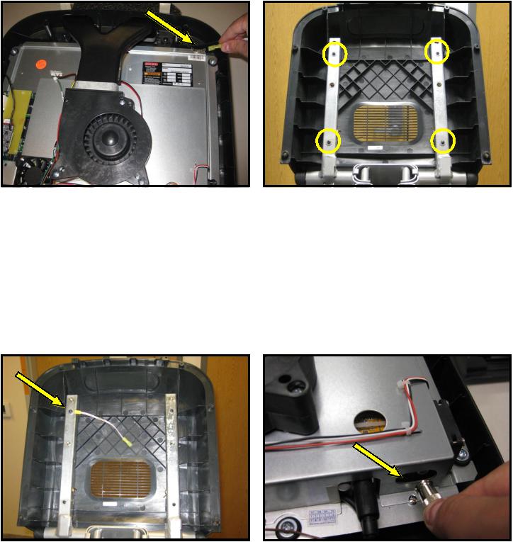
Step 5.
Disconnect the ground cable from the ground quick disconnect tab on the embedded display. Save the cable for later use.
Step 7.
Attach the ground cable to upper left screw on the mounting bracket and secure tightly.
Step 6.
Mount the back cover to the display mounting bracket using four (4) M4 x 0.7 x 19mm long Phillips head screws and four (4) M4 flat washers.
Step 8.
Pullout the coax adapter from the tuner card on the embedded display.
13 |
620-7921 Rev A |
Before |
|
After |
|
|
|
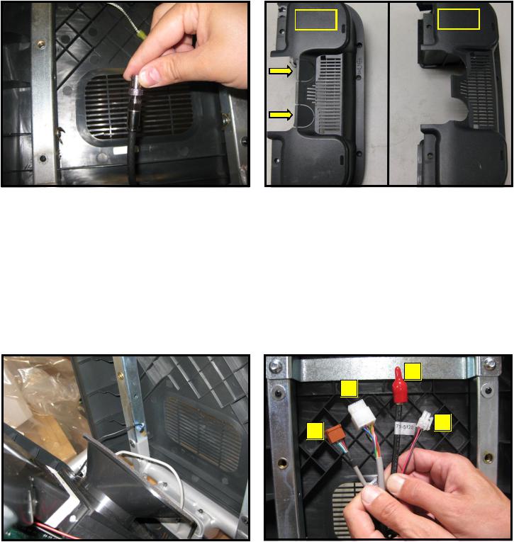
Step 9. |
Step 10. |
Now screw in the coax adaptor to the coax ca- |
Go back to the embedded display assembly and |
ble coming out of the base neck. |
remove the plastic tabs from the lower back |
|
cover. |
3
2
4
1
Step 11. |
Step 12. |
|
Take the embedded display assembly to the |
Identify the four cables coming out of the neck |
|
base unit. Hold the front display plastics at the |
and mounting bracket: |
|
top with one hand while connecting the cables |
1. |
Heart rate cable |
and harnesses with the other. |
2. |
Main I/O cable |
|
3. |
Coax cable |
|
4. |
DC power cable |
14 |
620-7921 Rev A |
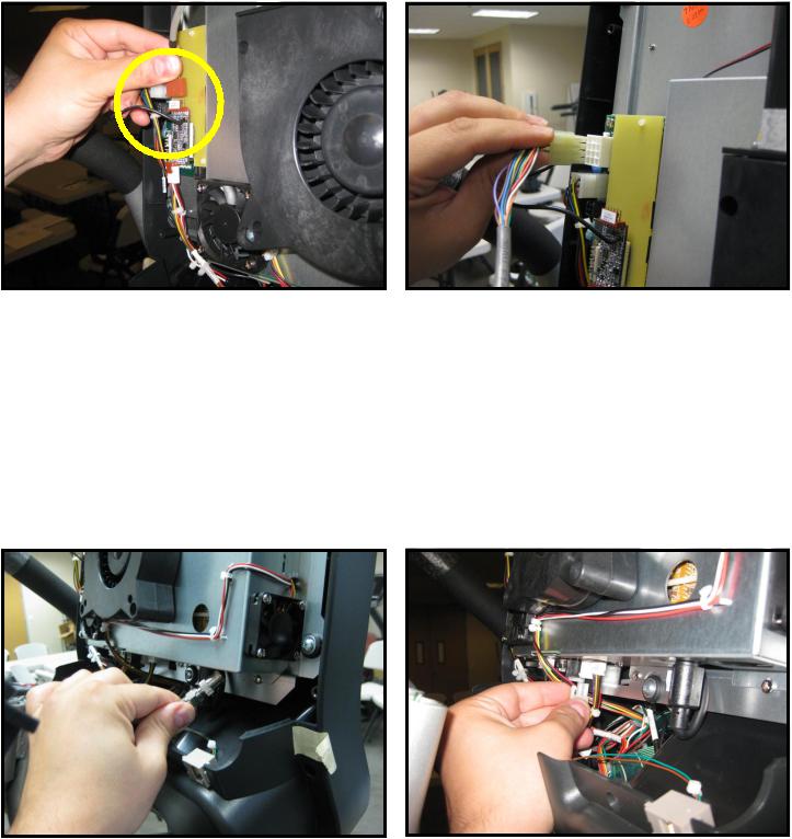
Step 13.
Plug-in the heart rate cable from the neck into the heart rate board connector on the FitCPU board of the embedded display assembly.
Step 15.
Next plug in the coax cable to the coax adapter on the tuner card of the embedded display assembly.
Step 14.
Plug-in the 12-pin main I/O cable from the neck to the 12 pin connector on the FitCPU board of the embedded display assembly.
Step 16.
Now plug in the DC power cable from the base neck to DC connectors on the embedded display assembly.
15 |
620-7921 Rev A |
Step 17.
Plug in the Heart rate ground cable into the quick disconnect tab on the display mount.
Step 18.
Plug in the ground cable coming from upper left side of the display mounting bracket into the quick disconnect tab on the embedded display assembly.
2
1
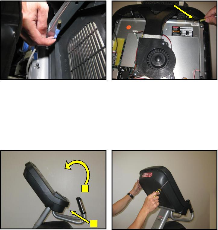
Step 19.
Assemble the front and back display parts together by sliding the bottom of the front display under the 2 tabs at the base first, then pressing front display against the back cover.
Caution: Be careful not to pinch any wires.
Step 20.
Using a Phillips head screw driver, secure the front display to the back with (8) M4 x 0.7 x 19mm long Phillips head screws.
16 |
620-7921 Rev A |
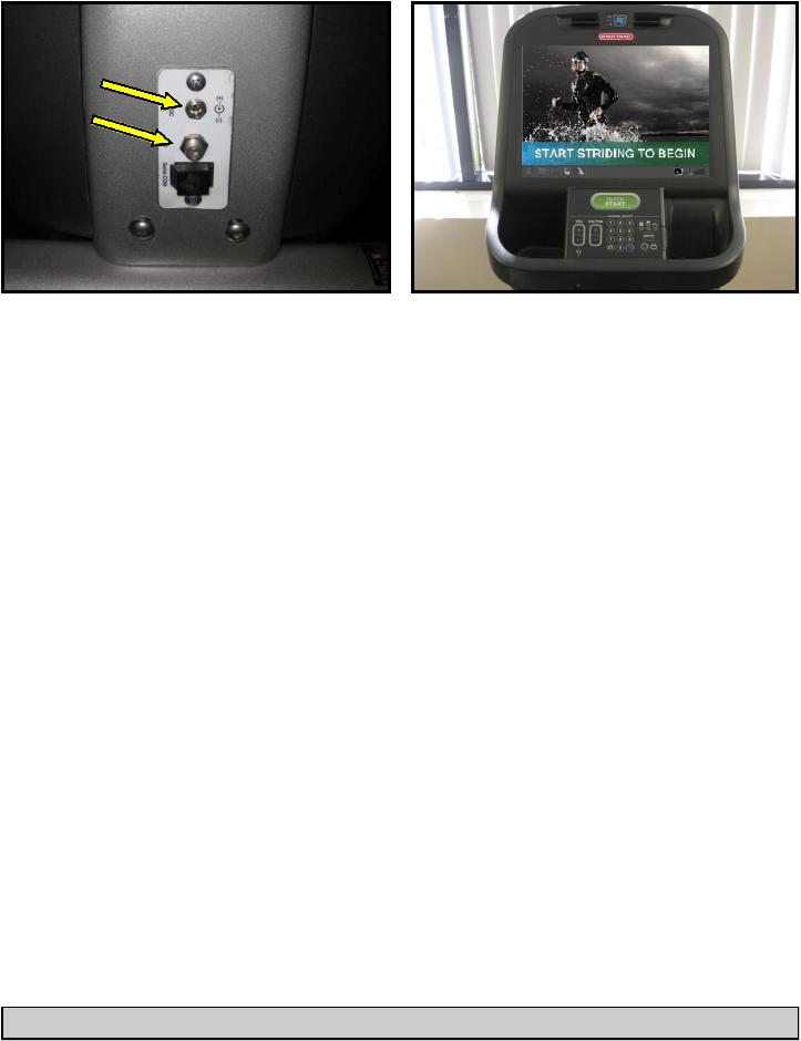
Step 21.
Now it is time to connect entertainment cable and power to the unit. Connect the in-house entertainment cable to the RF input at the base of the unit.
Take the power supply from the kit and plug the small barrel connector to the DC input. Then take the power adapter cable from the kit and plug it into the power supply and the electrical receptacle.
Step 22.
Turn power on. Perform a visual inspection, and test the features and functions of the unit prior to use.
Note: Refer to the User’s Manual for other settings and instructions.
YOU HAVE NOW COMPLETED THE EMBEDDED DISPLAY INSTALLATION
17 |
620-7921 Rev A |
 Loading...