


Operating Manual
Model 34700-2K/17700-2K
Recovery/Recycling/Recharging Unit
Model 17700-2K (for R-12 refrigerant)
Model 34700-2K (for R-134a refrigerant)
Recover, Recycle, and Recharge Unit
SAFETY DEFINITIONS: Follow all WARNING, CAUTION, IMPORTANT, and NOTE messages in this manual. These messages are defined as follows: WARNING means you may risk serious personal injury or death; CAUTION means you may risk personal injury, property damage, or unit damage; IMPORTANT means you may risk unit damage; and NOTEs provide clarity and helpful tips. These safety messages cover situations ROBINAIR is aware of. ROBINAIR cannot know, evaluate, and advise you as to all possible hazards. You must verify that conditions and procedures do not jeopardize your personal safety.
DISCLAIMER: Information, illustrations, and specifications contained in this manual are based on the latest information available at the time of publication. The right is reserved to make changes at any time without obligation to notify any person or organization of such revisions or changes. Further, ROBINAIR shall not be liable for errors contained herein or for incidental or consequential damages (including lost profits) in connection with the furnishing, performance, or use of this material. If necessary, obtain additional health and safety information from the appropriate government agencies and the vehicle, refrigerant, and lubricant manufacturers.
WARNINGS
ALLOW ONLY QUALIFIED PERSONNEL TO OPERATE THE UNIT. Before operating the unit, read and follow the instructions and warnings in this manual. The operator must be familiar with air conditioning and refrigeration systems, refrigerants, and the dangers of pressurized components. If the operator cannot read English, operating instructions and safety precautions must be read and discussed in the operator’s native language.
Si el operador no puede leer el inglés, las instrucciones de operación y las precauciones de seguridad deberán leerse y comentarse en el idioma nativo del operador.
Si l’utilisateur ne peut lire l’anglais, les instructions et les consignes de sécurité doivent lui être expliquées dans sa langue maternelle.
PRESSURIZED TANK CONTAINS LIQUID REFRIGERANT. Do not overfill the internal storage vessel because overfilling may cause explosion and personal injury or death. Do not recover refrigerants into non-refillable containers; use only federally authorized refillable containers (DOT spec. 4BW or 4BA).
ALL HOSES MAY CONTAIN LIQUID REFRIGERANT UNDER PRESSURE. Contact with refrigerant may cause personal injury. Wear protective equipment, including safety goggles. Disconnect hoses using extreme caution.
DO NOT BREATHE REFRIGERANT AND LUBRICANT VAPOR OR MIST. Exposure may cause personal injury, especially to the eyes, nose, throat, and lungs. Use the unit in locations with mechanical ventilation that provides at least four air changes per hour. If accidental system discharge occurs, ventilate the work area before resuming service.
DO NOT USE AN EXTENSION CORD. An extension cord may overheat and cause fire. If you must use an extension cord, use the shortest possible cord with a minimum size of 14 AWG.
TO REDUCE THE RISK OF FIRE, do not use the unit in the vicinity of spilled or open containers of gasoline or other flammable substances.
DO NOT USE COMPRESSED AIR TO PRESSURE TEST OR LEAK TEST THE UNIT OR VEHICLE AIR CONDITIONING SYSTEM. Some mixtures of air and R-134a refrigerant are combustible at elevated pressures. These mixtures are potentially dangerous and may result in fire or explosion causing personal injury or property damage.
USE THE 17700-2K UNIT WITH R-12 REFRIGERANT ONLY. The unit is for recovering, recycling, and recharging only R-12 refrigerant! Do not attempt to adapt the unit for another refrigerant. Do not mix refrigerant types through a system or in the same container; mixing of refrigerants will cause severe damage to the unit and the vehicle air conditioning system.
USE THE 34700-2K UNIT WITH R-134a REFRIGERANT ONLY. The unit is for recovering, recycling, and recharging only R-134a refrigerant! Do not attempt to adapt the unit for another refrigerant. Do not mix refrigerant types through a system or in the same container; mixing of refrigerants will cause severe damage to the unit and the vehicle air conditioning system.
HIGH VOLTAGE ELECTRICITY INSIDE THE UNIT HAS A RISK OF ELECTRICAL SHOCK. Exposure may cause personal injury. Disconnect the power before servicing the unit.
OPERATING NOTE: At temperatures exceeding 120°F / 49°C, wait 10 minutes between recovery jobs.

|
Table of Contents |
Introduction .............................................................................................. |
2 |
Glossary of Terms ................................................................................. |
2 |
Setup Instructions.................................................................................... |
2 |
Initial Setup ............................................................................................. |
4 |
Vacuum Pump Initial Fill ......................................................................... |
5 |
Installation Routine ................................................................................. |
5 |
Operating Guidelines ............................................................................... |
6 |
Using the Selection Menu ....................................................................... |
6 |
Change Filter .......................................................................................... |
6 |
Recycle ................................................................................................... |
7 |
Tank Refill ............................................................................................... |
7 |
Vacuum Oil Time .................................................................................... |
7 |
Filter Capacity......................................................................................... |
7 |
Basic/Advanced Prompts ....................................................................... |
8 |
Selecting a Unit (Metric/English) ............................................................ |
8 |
Language Select ..................................................................................... |
8 |
Change Defaults ..................................................................................... |
9 |
Using the Control Panel .......................................................................... |
9 |
Keypad Functions ................................................................................. |
10 |
Operating Instructions........................................................................... |
11 |
Operating Tips ...................................................................................... |
11 |
Recovering Refrigerant ......................................................................... |
12 |
Evacuating the A/C System .................................................................. |
14 |
Replenishing A/C System Oil ............................................................... |
16 |
Recharging the A/C System ................................................................. |
17 |
Maintenance Instructions ...................................................................... |
19 |
Replacing the Filter-Drier ...................................................................... |
19 |
Changing the Vacuum Pump Oil .......................................................... |
20 |
Checking for Leaks ............................................................................... |
21 |
Electrical Protection .............................................................................. |
22 |
General Maintenance ........................................................................... |
22 |
Replacement Parts List ......................................................................... |
22 |
Flow Diagram.......................................................................................... |
24 |
Wiring Diagram....................................................................................... |
25 |
Limited Warranty .................................................................................... |
26 |
U.S. Patents: 4,523,897; 4,688,388 Re 33,212; 4,768,347; 4,805,416; 4,809,520; 4,878,356; 4,938,031; 5,005,369; 5,005,375; 5,038,578; 5,042,271; 5,209,653; 5,248,125; Australian Patent: 613,058; Canadian Patents: 1,311,621; 1,311,622; 2,012,620; 2,026,348; European Patent: 0 315 296 Bl; German Patent: 031296 Mexican Patent: 16208 OTHER U.S. AND FOREIGN PATENTS PENDING.
Mfd. by Robinair, SPX Corporation, Montpelier, OH 43543
1
34700-2K/17700-2K Cool-Tech Recovery/Recycling/Recharging Unit

Introduction
This manual contains important safety procedures concerning the operation, use, and maintenance of this product. Failure to follow the instructions contained in this manual may result in serious injury. If you are unable to understand any of the contents of this manual, please bring it to the attention of your supervisor. Do not operate this equipment unless you have read and understood the contents of this manual.
The 34700-2K models are used for R-134a vehicles, whereas the 17700-2K models are used for R-12 vehicles. Both models are designed to be compatible with existing service equipment and standard service procedures.
The 34700-2K and the 17700-2K models are UL-listed, single-pass systems that meet the SAE specifications for recycled refrigerant.
To validate your warranty, complete the warranty card attached to your unit, and return it within ten days from date of purchase.
Glossary of Terms
A/C System |
The air conditioning system being serviced. |
Unit |
The refrigerant recovery/recycling/recharging unit. |
Internal Storage Vessel The refillable refrigerant storage vessel designed
|
specifically for this unit. |
Source Tank |
A disposable tank of new refrigerant used to refill |
|
the internal storage vessel. |
Setup Instructions
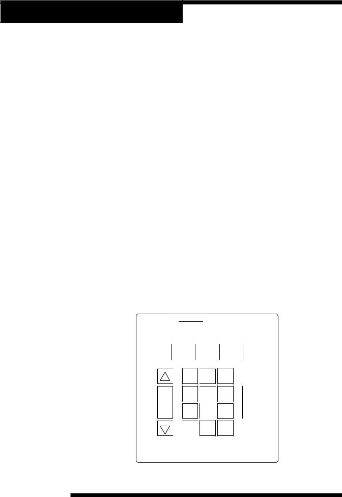
Low Side
Gauge High Side
Gauge
Keypad
|
0 |
|
2 |
2 |
2 |
0 |
1 |
1 |
|
00 |
|
10 |
|
0 |
|
|
0 |
|
0 |
|
3
RECOVER VACUUM
|
6 |
0 |
|
7 |
0 |
4 |
0 |
0 |
5 |
00 |
|
|
4 |
|
5 |
|
|
|
|
|
|
6 |
|
|
|
|
|
|
7 |
0 |
|
|
|
|
|
0 |
|
|
|
|
|
CLOSED
8 0
6 0
0
0 0 7
9
0
1 0 0
0
|
10 |
1 |
|
00 |
5 |
|
00 |
|
50 |
RECOVER VACUUM
2 |
5 |
0 |
|
|
00 |
|
|
2 |
0 |
5 |
|
2 |
0 |
|
5 |
|
|
|
|
0 |
|
3 |
|
|
0 |
|
|
50 |
|
HIGH
CLOSED
300 |
|
|
|
|
|
|
00 |
|
|
|
|
|
|
|
|
35 |
|
|
|
|
|
25 |
0 |
|
|
|
|
25 |
00 |
|
|
|
|
|
|
|
0 |
|
|
|
|
|
|
40 |
|
|
|
|
|
|
RECOVER |
VACUUM |
|
VAC-CHARGE |
CHARGE |
|
|
|
START |
|
STOP |
|
|
|
|
1 |
2 |
3 |
|
|
|
MENU |
4 |
5 |
6 |
F1 |
CHARGE |
7 |
8 |
9 |
|
||
OIL INJECT |
|
|
|
|
||
|
|
|
CLEAR |
0 |
ENTER |
|
RECOVER |
|
VACUUM |
|
VAC-CHARGE |
|
CHARGE |
||
|
|
|
|
|
|
|
|
|
|
|
|
|
|
|
|
|
|
START STOP
|
|
|
1 |
2 |
3 |
|
|
|
4 |
5 |
6 |
|
|
|
MENU |
|
F1 |
Low Side High Side |
Main Power |
7 |
8 |
9 |
|
Valve |
Valve |
Switch |
CLEAR |
0 |
ENTER |
|
|
|
|
||
INST0925
Diagram of the Control Panel
2
© 2001 Robinair, SPX Corporation
HIGH
LOW
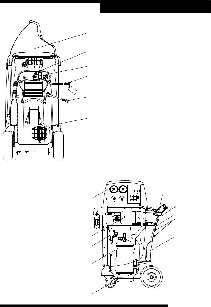
Diagram of Unit’s Components—
Internal View
1.Control Panel Assembly
2.Vacuum Pump
3.Internal Storage Vessel
4.Scale Assembly
5.Oil Drain Bottle
6.Hose Holder
7.Air Purge Control
8.Vacuum Pump Oil Fill
9.Sight Glass
10.Oil Drain
Setup Instructions
1
2
Diagram of Unit’s Components—
Side View
3
1. 1-800 Phone Number Decal
4
2. High Side Inlet
3. Low Side Inlet
4. Power Cord with Tag
55. Fill Hose
6. Tank Strap
6
INST0691
8
LOW |
HIGH |
|
1 |
2 |
3 |
CLOSED |
CLOSED |
|
|||
|
|
|
4 |
5 |
6 |
RECOVER |
RECOVER |
OIL INJECT |
7 |
8 |
9 |
VACUUM |
VACUUM |
CHARGE |
1 |
0 |
9
10
6
2 |
5 |
|
7
3
4 |
INST0946 |
3
34700-2K/17700-2K Cool-Tech Recovery/Recycling/Recharging Unit
Setup Instructions
KEYPAD FUNCTIONS
In addition to the number keys, the keypad contains special keys that accomplish specific operating functions.
START |
START— Begins, or resumes, a function. |
|
|
|
STOP— Terminates, or pauses, a function. |
|
|
|
STOP |
||
|
|
RECOVER— Activates the recovery sequence. |
|
|
|
RECOVER |
||
|
|
VACUUM— Activates vacuum and automatic recycling sequence. |
|
|
|
VACUUM |
||
|
|
VAC-CHARGE— Activates vacuum and automatic recycling sequence, |
|
|
|
VAC-CHARGE |
||
|
|
followed by a charge. |
|
|
|
|
|
CHARGE— Charges A/C system with a programmed amount of |
CHARGE |
||
|
|
refrigerant. |
|
|
|
MENU |
MENU— Enters the selection menu. |
|
|
|
UP/DOWN ARROWS— Scroll through menu items. |
|
|
|
|
|
|
|
|
|
|
|
|
F1 |
F1 (Inject Oil)— Injects oil into A/C system (active at end of vacuum). |
|
|
|
|
|
RECOVER |
|
VACUUM |
|
|
VAC-CHARGE |
|
CHARGE |
|||||||||||
|
|
|
|
|
|
|
|
|
|
|
|
|
|
|
|
|
|||
|
|
|
|
|
|
|
|
|
|
|
|
|
|
|
|
|
|||
|
|
|
|
|
START |
|
|
|
|
|
STOP |
||||||||
|
|
|
|
|
|
|
|
|
|
|
|
|
|
|
|
|
|
||
|
|
|
|
|
1 |
|
|
2 |
3 |
|
|
|
|
||||||
|
|
|
|||||||||||||||||
Diagram of Keypad |
4 |
|
|
5 |
|
|
6 |
|
|
|
|
||||||||
|
|
|
|
|
|||||||||||||||
|
|
|
|
|
|
||||||||||||||
|
|
|
|
|
|
|
|
|
|
|
|
|
|
|
|
|
|
|
|
|
|
|
|
|
|
|
|
|
|
|
|
|
|
|
|
|
|
F1 |
|
|
MENU |
|
|
|
|
||||||||||||||
|
7 |
|
|
8 |
|
|
9 |
|
|
|
|
||||||||
|
|
|
|
|
|
|
CLEAR |
|
0 |
|
|
ENTER |
|||||||
|
|
|
|
|
|
|
|
|
|
||||||||||
4
© 2001 Robinair, SPX Corporation

Setup Instructions
INITIAL SETUP
CAUTION! R-134a systems have special fittings (per SAE specifications) to avoid cross-contamination with R-12 systems. Do not attempt to adapt your unit for another refrigerant — system failure will result! Read and follow all warnings at the beginning of this manual before operating the unit.
CAUTION! Avoid the use of an extension cord, because the extension cord may overheat. However, if you must use an extension cord, use a No. 14 AWG minimum, and keep the cord as short as possible.
1.The first time the unit is powered up, it will start in the initial setup mode. If the initial setup must be performed again, it may be selected using the menu function.
2.The first step is to select a language. Use the UP and DOWN arrow keys to select the desired language. Press START to save the currently displayed language.
3.Next select the operating units. Toggle between UNITS ENGLISH and UNITS METRIC using the arrow keys. Press START to save the currently displayed choice.
4.Toggle between BASIC/ADVANCED using the ARROW keys. Use the BASIC PROMPT option to receive step-by-step, on-screen prompting through any procedure. Use ADVANCED PROMPT once you know the procedure and no longer need the step-by-step routine. Press START to save the currently displayed choice.
NOTE: This manual is written using the BASIC prompt option
Diagram of Hose Connections
Vacuum Pump Components |
1. |
Fill Hose |
||
|
|
|
||
1. Oil Filler Tube |
4. Sight Glass |
2. |
Quick-Couplers (34700 Only) |
|
2. Pump Exhaust |
5. Oil Drain Fitting |
|
|
|
3. Oil Fill Port |
6. Inlet |
|
|
|
|
|
1 |
|
|
|
6 |
2 |
|
|
|
3 |
HIGH |
|
|
LOW |
|
|
4 |
OPEN |
|
|
CLOSE |
|
1 |
|
|
|
|
5 |
|
|
|
2 |
|
INST0692 |
|
IMPORTANT!
You must press the MENU key to access all the functions.
INST0701
5
34700-2K/17700-2K Cool-Tech Recovery/Recycling/Recharging Unit

Setup Instructions
NOTE: The vacuum pump is shipped without oil in the reservoir. Before starting the pump, oil must be added to the pump, or damage to the pump may occur.
5.Press the START key to begin the oil fill process.
6.Attach the flexible tube and cap to the oil bottle, and pour eight ounces of vacuum pump oil into the fill port.
7.Press the START key. While the vacuum pump is running, slowly add oil until the level rises to the center of the reservoir's sight glass.
8.Press the STOP key, and replace the black plastic plug on the fill port.
9.Connect the service hoses, open both panel valves, and press START.
10.Connect the fill hose to a full source tank.
11.Open the tank valve. Invert the tank and install it on the back of the unit, making sure to secure the tank strap.
NOTE: If using a refillable tank, install the tank upside down, and connect the fill hose to the vapor valve.
12.Press START, and the unit will automatically run a five-minute vacuum to clear all internal air.
13.After the vacuum is complete, press START to begin filling the internal storage vessel.
14.The unit stops when a sufficient amount of refrigerant has been transferred to the internal tank, or when the source tank is empty. Press the STOP key to pause the process. Press STOP again to exit, or START to resume. This process takes 15-20 minutes.
NOTE: Add at least 8 lb. (3.6 kg) of refrigerant before stopping the process to ensure enough refrigerant is available for charging.
15.When the fill process is complete, you may press STOP to exit.
16.The unit is now ready to operate.
NOTE: There is no need to calibrate the scale, because it is calibrated at the factory.
1 
 2
2 
 3
3
4 
 5
5 
 6
6
7 8 
 9
9

 0
0 

IMPORTANT!
For maximum performance, change the vacuum pump oil frequently.
IMPORTANT!
The pump must be running when adding oil.
1
2
3
1.Oil Fill
2.Sight Glass
3. Oil Drain
INST0947
6
© 2001 Robinair, SPX Corporation

Operating Guidelines
USING THE SELECTION MENU
1.Press the MENU button. The top line of the display reads SETUP MENU.
2.Use the UP and DOWN arrow keys to scroll through the menu choices displayed on the second line. The menu choices are:
1. SELECT LANGUAGE |
7. VACUUM OIL TIME |
2. SELECT UNITS (ENGLISH/METRIC) |
8. CHANGE VACUUM PUMP OIL |
3. TANK REFILL |
9. SELECT PROMPTS |
4. RECYCLE ONLY |
10. CHANGE DEFAULTS (password protected) |
5. FILTER CAPACITY |
11. VERSION X.XX |
6. CHANGE FILTER
3.Press START to make a choice from the menu. Press STOP to pause any process, and STOP a second time to exit any process.
CHANGE FILTER
The filter-drier removes acid, particulates, and water from the refrigerant. Change the filter-drier after 150 pounds (68 kg) of refrigerant has been filtered. See the REPLACING THE FILTER DRIER section on the following page, as well as the Maintenance Section, for instructions.
RECYCLE
Manual recycling may be necessary if excessive air and/or moisture is recovered from the A/C system.
1.Press the MENU key. Use the arrow keys to select RECYCLE ONLY, and press START to begin.
2.Press the START button to start recycling. To pause recycling, press the STOP key. To terminate recycling, press the STOP key again, or press START to resume.
TANK REFILL
1.Press the MENU key. Use the arrow keys to select TANK REFILL, and press START to begin.
2.Connect the fill hose to the source tank.
3.Open the tank valve. Invert the tank, install it on the back of the unit, and secure the tank strap.
7
34700-2K/17700-2K Cool-Tech Recovery/Recycling/Recharging Unit

Operating Guidelines
NOTE: If using a refillable tank, install the tank upside down, and connect the fill hose to the vapor valve.
4.Press the START key, and the tank automatically refills. The unit stops when a sufficient amount of refrigerant has been transferred to the internal tank, or if the source tank is empty. Press the STOP key to pause the process. Press STOP again to exit, or START to resume.
5.When the fill process is complete, press STOP to exit.
VACUUM OIL TIME
This function displays how long the vacuum pump has run since the last oil change.
1.Press the MENU key. Use the arrow keys to select VACUUM OIL TIME, and press START to begin.
2.The display reads: OIL TIME = XX:XX This shows how long the pump has run since the last oil change. The time resets to zero after a VACUUM PUMP OIL CHANGE. See page 20 of this manual for details.
3.Press STOP to exit.
FILTER CAPACITY
This function is used to show the operator how many pounds or kilograms of refrigerant have been recovered since the last filter change.
1.Press the MENU key. Use the arrow keys to select FILTER CAPACITY, and press START to begin.
2.The display reads: FILTERED= XXXlbs(kg). This shows how much refrigerant has passed through the filter. The amount filtered resets to zero after a FILTER CHANGE. See page 19 of this manual for details.
3.Press STOP to exit.
SELECT PROMPT (BASIC/ADVANCED)
Use the BASIC PROMPT option to receive step-by-step, on-screen prompting through any procedure. Use ADVANCED PROMPT once you know the procedure and no longer need the step-by-step routine.
1.Press the MENU key. Use the arrow keys to choose SELECT PROMPT, and press START to begin.
2.Toggle between BASIC/ADVANCED using the ARROW keys.
3.Press START to save the current choice and exit.
NOTE: This manual is written for the BASIC PROMPT option.
8
© 2001 Robinair, SPX Corporation
 Loading...