


Installation Instructions
for Topload Washers
Inside..................................... |
|
Washer Dimensions........................................................... |
2 |
Before You Start................................................................ |
2 |
Installation......................................................................... |
3 |
Installer Checklist.............................................................. |
Back Cover |
Date Purchased ________________
Model Number ________________
Serial Number _________________
Para bajar una copia de estas instrucciones en español, visite www.speedqueen.com. Keep these instructions for future reference.
(If this machine changes ownership, this manual must accompany machine.)
www.speedqueen.com |
Part No. 201471R2 |
May 2010 |

Washer Dimensions
28 in. (71.1 cm) |
22.13 in. (56.2 cm) |
in. (73.7 cm) |
*43 in. (109.2 cm) |
*36 in. (91.4 cm) |
*53 in. (134.6 cm) |
*40.25 in. (102.2 cm) |
*29 |
|
|
|
|
|
|
|
|
|
|
|
|
|
|
|
|
|
|
|
|
|
|
|
|
|
|
|
|
|
|
|
|
|
|
|
|
|
|
|
|
|
|
|
|
|
|
|
|
|
|
|
|
|
|
|
|
|
|
|
|
|
|
|
|
|
|
|
|
|
|
|
|
|
|
|
|
|
|
|
|
|
|
|
|
|
.4 in. |
|
|
|
|
|
|
|
|
|
|
|
|
|
|
|
|
|
|
|
|
|
|
|
|
|
|
|
|
|
|
|
|
|
|
|
|
|
|
|
|
|
|
|
|
|
|
|
|
|
|
|
|
||
|
|
|
|
|
|
25.6 in. (65 cm) |
|
|
|
|
|
|
(10.2 mm) |
|
|
|
|
|
|
|
|
26 in. (66 cm) |
|
|
|
|
|
||||||
|
|
|
|
|
|
|
|
|
|
|
|
|
|
|
|
|
|
|
|
|
|
||||||||||||
*With leveling legs turned into base. |
|
|
|
|
|
|
|
|
|
|
|
|
|
|
|
|
|
|
|
|
|
|
|
|
|
TLW2075N |
|||||||
Figure 1
Before You Start
Supplies
For most installations, the basic supplies you will need are:

 1
1

 2
2
3 |
4 |
5 |

 6
6
TLW1978N
1Safety Glasses
2Wood Block
3Wrench
4Screwdriver
5Pliers
6Level
Parts Included
An accessories bag has been shipped inside your washer. It includes:
Two fill hoses with washers and filter screens. Refer to step 3 of Installation.
Four rubber feet. Refer to step 5 of Installation.
Beaded strap. Refer to step 4 of Installation.
Installation Instructions.
User’s Guide.
Product Registration Card.
Warranty Bond.
NOTE: If the washer is delivered on a cold day (below freezing), or is stored in an unheated room or area during the cold months, do not attempt to operate it until the washer has had a chance to warm up.
NOTE: Install dryer before washer. This allows room for attaching exhaust duct.
Figure 2
2 |
© Copyright, Alliance Laundry Systems LLC – DO NOT COPY or TRANSMIT |
201471 |
Installation
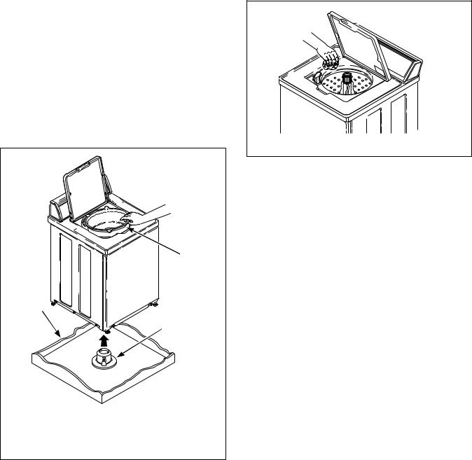
Step 1: Remove the Shipping Brace and Shipping Plug
Remove the shipping brace from under the lid.
The shipping plug will be released from the base of the washer when removing the cardboard base from the washer. Refer to Figure 3.
NOTE: Do not tilt washer to front or sides when moving.
Save the shipping brace and plug. They must be reinstalled whenever washer is moved or transported to a new location. This will prevent damage to the washer. Refer to the User’s Guide for instructions on reinstalling the shipping materials.
1
3
2
TLW1975N
1Shipping Brace
2Shipping Plug
3Cardboard Base
Figure 3
Step 2: Wipe Out Inside of Washtub
Prior to first wash, use an all purpose cleaner, or a detergent and water solution, and a damp cloth to remove shipping dust from inside of washtub.
TLW2009N
Figure 4
201471 |
© Copyright, Alliance Laundry Systems LLC – DO NOT COPY or TRANSMIT |
3 |

Step 3: Connect Fill Hoses
WARNING
Under certain conditions, hydrogen gas may be produced in a hot water system that has not been used for two weeks or more. HYDROGEN GAS IS EXPLOSIVE. If the hot water system has not been used for such a period and before using the washer, turn on all hot water faucets and let the water flow from each for several minutes. This will release any accumulated hydrogen gas. The gas is flammable. Do not smoke or use an open flame during this time.
W029
Water Supply
Water supply faucets must fit standard 3/4 inch (19.1 mm) female garden hose couplings. DO NOT USE SLIP-ON OR CLAMP-ON CONNECTIONS.
Water supply faucets should be readily accessible to permit turning them off when washer is not being used.
Recommended cold water temperature is 50o to 75o Fahrenheit (10o to 24o Celsius). Recommended maximum hot water temperature is 125o Fahrenheit
(51o Celsius). Warm water is a mixture of hot and cold water. Warm water temperature is dependent upon water temperature and pressure of both the hot and cold water supply lines.
WARNING
To prevent personal injury, avoid contact with inlet water temperatures higher than 125° Fahrenheit (51° Celsius) and hot surfaces.
W748
Water pressure must be a minimum of 20 to a maximum of 120 pounds per square inch (138 to 827 kPa) static pressure measured at the faucet.
NOTE: Water pressure under 20 pounds per square inch (138 kPa) will cause an extended fill time in the washer.
Turn on the water faucets and flush the lines for approximately two minutes to remove any foreign material that could clog the screens in the water mixing valve.
NOTE: When installing in newly constructed or renovated buildings, it is very important to flush the lines since build-up may have occurred during construction.
Connecting Hoses
Remove the two plain rubber washers and two filter screens from the accessories bag. Install them into each end of the fill hoses as shown in Figure 5. The screen must be facing outward.
Screw hose couplings with the filter screens onto the water faucets until they are finger-tight. Then, using a pliers, screw approximately 1/4 turn. Use the red color-coded hose for the hot water connection and the blue color-coded hose for the cold water connection.
Screw hose couplings from other end of hoses onto the water mixing valve until they are finger-tight. Then, using a pliers, screw approximately 1/4 turn. Refer to Figure 6. Make sure the red color-coded hose from the hot water faucet goes to the water mixing valve marked “H” and the blue color-coded hose from the cold faucet goes to the valve marked “C”.
IMPORTANT: Do not cross thread or overtighten couplings. This will cause them to leak.
Turn water on and check for leaks. If leaks are found, turn off the water, unscrew hoses and reinstall them until there are no leaks.
IMPORTANT: Turn off water supply whenever there will be an extended period of non-use.
4 |
© Copyright, Alliance Laundry Systems LLC – DO NOT COPY or TRANSMIT |
201471 |
 Loading...