


REFERENCE & INSTALLATION MANUAL
SPECTRA CONTROL PANELS V2.1
1728EX and 1728 |
|
1738EX and 1738 |
|
|
|

TABLE OF CONTENTS |
|
Introduction .......................................................................................................................................... |
4 |
Features............................................................................................................................................................................................... |
4 |
Specifications....................................................................................................................................................................................... |
4 |
Detectors, Keypads and Expansion Modules ...................................................................................................................................... |
5 |
Installation ............................................................................................................................................ |
7 |
Location and Mounting ........................................................................................................................................................................ |
7 |
Earth Ground ....................................................................................................................................................................................... |
8 |
AC Power............................................................................................................................................................................................. |
9 |
Backup Battery .................................................................................................................................................................................... |
9 |
Auxiliary Power Terminals ................................................................................................................................................................... |
9 |
Telephone Line Connection............................................................................................................................................................... |
10 |
Bell Output Connection...................................................................................................................................................................... |
10 |
Programmable Output Connections................................................................................................................................................... |
10 |
Single Zone Inputs............................................................................................................................................................................. |
11 |
Double Zone Inputs (with ATZ Option only)....................................................................................................................................... |
11 |
Keypad and Keypad Zone Connections ............................................................................................................................................ |
12 |
Keyswitch Connections...................................................................................................................................................................... |
13 |
Fire Circuits........................................................................................................................................................................................ |
13 |
Programming Methods........................................................................................................................ |
13 |
WinLoad Software for Windows......................................................................................................................................................... |
13 |
Programming Using a Keypad........................................................................................................................................................... |
13 |
Configuring The LED Keypads .......................................................................................................................................................... |
14 |
Programming Using A Paradox Memory Key .................................................................................................................................... |
16 |
Access Codes ..................................................................................................................................... |
16 |
Access Code Length.......................................................................................................................................................................... |
17 |
Installer Code (Default: 000000)........................................................................................................................................................ |
17 |
System Master Code (Default: 123456)............................................................................................................................................. |
17 |
User Code Options ............................................................................................................................................................................ |
17 |
Lock Master Code.............................................................................................................................................................................. |
18 |
Duress Code...................................................................................................................................................................................... |
18 |
Zone Programming.............................................................................................................................. |
19 |
What is an Expansion Input? ............................................................................................................................................................. |
19 |
Reassign Keypad Zone 2 .................................................................................................................................................................. |
19 |
Reassign Zones to Expansion Inputs (1728EX & 1728 Only) ........................................................................................................... |
20 |
Zone Programming ............................................................................................................................................................................ |
20 |
Zone Definitions................................................................................................................................................................................. |
21 |
Exclusive Zone Definitions................................................................................................................................................................. |
22 |
Zone Partition Assignment................................................................................................................................................................. |
23 |
Zone Options ..................................................................................................................................................................................... |
23 |
Zone Speed ....................................................................................................................................................................................... |
25 |
EOL Zones......................................................................................................................................................................................... |
25 |
ATZ - Zone Doubling (1728 and 1738 only)....................................................................................................................................... |
25 |
Arming and Disarming Options........................................................................................................... |
27 |
Switch To Stay Arming....................................................................................................................................................................... |
27 |
Stay Arming with Delay...................................................................................................................................................................... |
27 |
Regular Arming switches to Force Arming......................................................................................................................................... |
27 |
Restrict Arming On Battery Fail ......................................................................................................................................................... |
27 |
Restrict Arming On Tamper Failure ................................................................................................................................................... |
27 |
Timed Auto-Arming............................................................................................................................................................................ |
28 |
No Movement Auto-Arming................................................................................................................................................................ |
28 |
Auto-Arming Options.......................................................................................................................................................................... |
28 |
One-Touch Arming............................................................................................................................................................................. |
29 |
Exit Delay........................................................................................................................................................................................... |
29 |
Bell Squawk On Arm/Disarm With Keypad........................................................................................................................................ |
29 |
Bell Squawk On Arm/disarm with Remote Control ............................................................................................................................ |
29 |
No Exit Delay When Arming with Remote Control............................................................................................................................. |
29 |
No Exit Delay Beeps and No Bell Squawk When Stay Arming.......................................................................................................... |
29 |
Alarm Options .................................................................................................................................... |
30 |
Bell Cut-Off Timer .............................................................................................................................................................................. |
30 |
Recycle Alarm.................................................................................................................................................................................... |
30 |
Tamper Recognition........................................................................................................................................................................... |
30 |
Keypad Panic Options ....................................................................................................................................................................... |
31 |
Panic Lockout Timer .......................................................................................................................................................................... |
31 |
Reporting and Dialer settings............................................................................................................. |
32 |
Reporting/Dialer (Enable/Disable) ..................................................................................................................................................... |
33 |
Report Codes..................................................................................................................................................................................... |
33 |
Central Station Telephone Numbers.................................................................................................................................................. |
36 |
Partition Account Numbers ................................................................................................................................................................ |
36 |
Reporting Formats ............................................................................................................................................................................. |
36 |
Pager Delay ....................................................................................................................................................................................... |
37 |
Event Call Direction ........................................................................................................................................................................... |
38 |
Dialing Method................................................................................................................................................................................... |
38 |
Pulse Ratio ........................................................................................................................................................................................ |
38 |
Bell on Communication Failure.......................................................................................................................................................... |
38 |
Dial Tone Delay ................................................................................................................................................................................. |
38 |
Maximum Dialing Attempts ................................................................................................................................................................ |
39 |
Delay Between Dialing Attempts........................................................................................................................................................ |
39 |
Alternate Dial Option.......................................................................................................................................................................... |
39 |
Recent Close Delay ........................................................................................................................................................................... |
39 |
Auto Test Report................................................................................................................................................................................ |
39 |
Power Failure Report Delay............................................................................................................................................................... |
39 |
Disarm Reporting Options.................................................................................................................................................................. |
40 |
Zone Restore Report Options............................................................................................................................................................ |
40 |
Telephone Line Monitoring (TLM)...................................................................................................................................................... |
40 |
Programmable Outputs...................................................................................................................... |
41 |
PGM Activation Event........................................................................................................................................................................ |
41 |
PGM Deactivation Event.................................................................................................................................................................... |
41 |
PGM Delay ........................................................................................................................................................................................ |
42 |
PGM Normal State............................................................................................................................................................................. |
42 |
PGM2 Strobe Options (1738EX and 1738 only)................................................................................................................................ |
42 |
Alarm Relay Options (1738EX and 1738 only) .................................................................................................................................. |
42 |
System Settings.................................................................................................................................. |
43 |
Hardware Reset................................................................................................................................................................................. |
43 |
Installer Lock...................................................................................................................................................................................... |
43 |
Keypad Lockout Feature.................................................................................................................................................................... |
43 |
Battery Charge Current...................................................................................................................................................................... |
43 |
Partitioning......................................................................................................................................................................................... |
43 |
System Real-Time Clock ................................................................................................................................................................... |
44 |
Clock Adjust....................................................................................................................................................................................... |
44 |
Keypad Tamper Supervision.............................................................................................................................................................. |
44 |
Keypad Audible Trouble Warning ...................................................................................................................................................... |
44 |
Confidential Mode.............................................................................................................................................................................. |
45 |
Installer Quick Functions Keys........................................................................................................................................................... |
45 |
4-Output Bus Module Supervision ..................................................................................................................................................... |
45 |
Printer Bus Module Supervision......................................................................................................................................................... |
46 |
Zone Expansion Bus Module Supervision ......................................................................................................................................... |
46 |
Wireless Bus Module Supervision ..................................................................................................................................................... |
46 |
Wireless Transmitter Low Battery Supervision .................................................................................................................................. |
46 |
Wireless Transmitter Supervision Options......................................................................................................................................... |
46 |
ReProgram All Expansion Modules ................................................................................................................................................... |
47 |
Settings for WinLoad Software........................................................................................................... |
48 |
Panel Answer Options ....................................................................................................................................................................... |
48 |
Panel Identifier................................................................................................................................................................................... |
48 |
PC Password ..................................................................................................................................................................................... |
48 |
PC Telephone Number ...................................................................................................................................................................... |
48 |
Call WinLoad Software ...................................................................................................................................................................... |
49 |
Answer WinLoad Software................................................................................................................................................................. |
49 |
Auto Event Buffer Transmission ........................................................................................................................................................ |
49 |
Call Back WinLoad............................................................................................................................................................................. |
49 |
User Operation................................................................................................................................... |
50 |
Trouble Display.................................................................................................................................................................................. |
50 |
Programming Access Codes ............................................................................................................................................................. |
51 |
Disarming & Deactivating an Alarm ................................................................................................................................................... |
52 |
Regular Arming.................................................................................................................................................................................. |
52 |
Stay Arming ....................................................................................................................................................................................... |
52 |
Instant Arming.................................................................................................................................................................................... |
52 |
Force Arming ..................................................................................................................................................................................... |
53 |
Manual Bypass Programming............................................................................................................................................................ |
53 |
One-Touch Arming............................................................................................................................................................................. |
54 |
Keyswitch Arming .............................................................................................................................................................................. |
54 |
Panic Alarms...................................................................................................................................................................................... |
54 |
Auto-Arming....................................................................................................................................................................................... |
54 |
Alarm Memory Display....................................................................................................................................................................... |
54 |
Programming Chime Zones............................................................................................................................................................... |
55 |
Keypad Muting................................................................................................................................................................................... |
55 |
Keypad Backlight (1686H and 1686V only) ....................................................................................................................................... |
55 |
FCC WARNINGS .................................................................................................................................. |
56 |
Index.................................................................................................................................................... |
58 |
LIST OF TABLES |
|
Transformer Requirements Table........................................................................................................................................................ |
9 |
Current Consumption Table................................................................................................................................................................. |
9 |
Decimal and Hexadecimal Programming Table................................................................................................................................. |
14 |
Zone Recognition Table..................................................................................................................................................................... |
19 |
Example............................................................................................................................................................................................. |
19 |
Zone Display with 10-Zone LED Keypad........................................................................................................................................... |
20 |
Special Keys for Telephone Numbers ............................................................................................................................................... |
36 |
Reporting Formats ............................................................................................................................................................................. |
36 |
Zone Tamper Report Code for Keypad Tamper Supervision Failure ................................................................................................ |
44 |
Trouble List ........................................................................................................................................................................................ |
50 |

PART 1: INTRODUCTION
1.1FEATURES
•Up to 16 fully programmable zones
•Two completely independent partitions. Many of the features and options in the Spectra System can be independently set for each partition such as event reporting, entry/exit delay, auto-arming and many more. All zones, the keyswitches and all user codes are assigned to specific partitions, which makes this a true partitioned system.
•Communication bus facilitates the adding, programming and monitoring of all expansion modules.
•1 Installer Code and 48 User Codes (including: 1 System Master, 2 Masters, and 1 Duress)
•1738/EX: 2 on-board, fully programmable outputs (PGMs) and 1 optional 5A alarm relay
•1728/EX: 1 on-board, fully programmable output
•Simple, direct and logical programming
•Event Call Direction: The Spectra Series Control Panel events are divided into 5 groups of events. Each of these event groups can be programmed with a separate dialing sequence.
•Two 32-digit Central Station Telephone Numbers and one 32-digit Backup Telephone Number
•Contact ID, Pager Format and many more High-Speed Communication Formats
•"False Alarm Prevention" features such as: Intellizone, Auto Zone Shutdown, Beep on Exit Delay, Programmable Delay Before Alarm Transmission, and Recent Closing Report
•Regular Arming, Stay Arming, Instant Arming, Force Arming, One-Touch Arming, Auto-Arming, or Keyswitch Arming
•256 Event Buffer with time stamp
•Telephone Line Supervision
•Keypad activated panic alarms
•Compatible with Winload Security System Management Software for Windows®
1.2SPECIFICATIONS
1.2.1SPECTRA 1728/EX AND 1738/EX CONTROL PANELS
• |
AC Power:* |
16VAC transformer with minimum 20VA rating (Rec.: 40VA), 50 to 60Hz |
• |
Battery: |
12VDC, 4Ah/7Ah |
• |
Aux. Power:+ |
600mA typical, 700mA maximum, fuseless shutdown @ 1.1A |
• |
Bell Output:++ |
1A, fuseless shutdown @ 3A |
• |
PGM Outputs: |
PGM1 = 150mA for 1728EX and 1728 |
|
|
PGM1 and PGM2 = 1A for 1738EX and 1738 only |
1.2.2SPECTRA KEYPADS (1686H, 1686V, 1689 & 1641)
• Power input: |
9-16VDC, |
•1 standard keypad zone
•On-board Tamper Switch (optional)
1686H & 1686V 10-Zone LED Keypad
• |
Current Consumption: |
62 to 116mA |
1689 16-Zone LED Keypad |
|
|
• |
Current Consumption: |
50 to 117mA |
1641 32-Character LCD Keypad |
|
|
• |
Current Consumption: |
60 to 80mA |
• |
PGM: |
1 with 50mA current limit |
• |
LCD: |
Super Twisted Nematic display (STN), Wide viewing angle, Backlight & |
|
|
Contrast adjustable |
* Only the 16.5VAC, 40VA version is UL listed. + 200mA typical for UL installations
++1A for UL installations total, including PGM options
4 REFERENCE & INSTALLATION MANUAL
1.3DETECTORS, KEYPADS AND EXPANSION MODULES
If you would like to obtain more information on our line of keypads, security system accessories or other security products, please contact your local Paradox distributor or visit our web site at http://www.paradox.ca.
1.3.1SPECTRA 1686H AND 1686V 10-ZONE LED KEYPADS
The elegant Spectra 1686H/1686V LED keypads’ patented Key-light feature provides a user-friendly display of the system’s current status. For example, if zone 5 is open, the [5] key turns on. What could be simpler? Designed to be compatible with any Spectra Series control panel, our Eurostyle Spectra keypads eliminate stocking and ordering concerns.
1.3.2SPECTRA 1689 16-ZONE LED KEYPADS
The Spectra 1689 LED keypad’s brilliant display provides instant feedback of the system’s current status. Designed to be compatible with any Spectra Series control panel, this ergonomic and user-friendly keypad will complete any installation.
1.3.3SPECTRA 1641 LCD KEYPAD
The 1641 is a 32-character programmable LCD keypad which includes a zone input as well as a PGM output. View zone, event and trouble status for one or more partitions, display entry/exit delay, adjust contrast, backlight, and many other features. Most messages in the LCD keypad are programmable.
1.3.4PRINTER BUS MODULE
The Printer Module (APR3-PRT1) provides you with the ability to automatically print events as they occur in the system or the events can be stored in the module’s event buffer so you can print the events manually. The events can be sent to a dot matrix printer or can be viewed and printed from a computer. Includes a 50mA PGM output. Due to its Auto-panel Recognition feature, modules with the APRprefix are compatible with Spectra (versions 2.0 and higher) and Digiplex. Modules with the APR3prefix are compatible with Spectra( versions 2.0 and higher), Digiplex and DigiplexNE.
1.3.54-OUTPUT BUS MODULE*
When connected to the Spectra communication bus, this module (APR3-PGM4) will provide four additional 5A programmable outputs to the Spectra system. Due to its Autopanel Recognition feature, modules with the APRprefix are compatible with Spectra (versions 2.0 and higher) and Digiplex. Modules with the APR3prefix are compatible with Spectra( versions 2.0 and higher), Digiplex and DigiplexNE.
*Not UL listed
SPECTRA SERIES 5
1.3.6INTOUCH VOICE-ASSISTED ARM/DISARM BUS MODULE*
Using a touch-tone telephone, users can arm or disarm their security system from a distance as well as activate or deactivate the APR3-ADM2’s on-board PGM output. Due to its Auto-panel Recognition feature, modules with the APRprefix are compatible with Spectra (versions 2.0 and higher) and Digiplex. Modules with the APR3prefix are compatible with Spectra( versions 2.0 and higher), Digiplex and DigiplexNE.
1.3.7ZONE EXPANSION BUS MODULES*
Connected to the Spectra control panel’s communication bus, the fully supervised zone expansion modules provide you with up to 4 (SPC/APR3-ZX4) or up to eight (SPC/APR3-ZX8) additional hardwired inputs and one normally open 50mA PGM output (SPC/APR3-ZX8 only). Due to its Auto-panel Recognition feature, a module with the APRprefix is compatible with Spectra (versions 2.0 and higher) and Digiplex. Modules with the APR3prefix are compatible with Spectra( versions 2.0 and higher), Digiplex and DigiplexNE.
1.3.8WIRELESS BUS MODULE*
Connected to the Spectra control panel’s communication bus, the fully supervised Wireless Bus Module (SPC-319) allows you to add up to eight fully programmable remote controls and up to eight Liberator Wireless Detectors and Contact Switches (door contacts). The SPC-319 also provides one programmable 5A relay (PGM). A second 5A programmable relay (PGM) is available as an option.
1.3.9PARAVOXTM - VOICE DIALER*
In areas where security system monitoring is not available, let the sophisticated Paravox voice dialer take over. Compatible with any control panel, the Paravox will verbally report system status by phone, advising of detection of burglary, fire, flood or any other situation programmed to generate a report condition. Fully programmable over the telephone (no external keypad required), the Paravox guides the end user through all system functions with a full set of voice prompts. All the user needs to remember is their P.I.N. The “Key Ahead” feature eliminates the frustration and time wasted for experienced operators by allowing them to key-in selections before a prompt ends.
1.3.10DIGITAL DETECTORS
The Paradox DigigardTM (50/60/70) digital motion detectors can immediately identify the signal produced by a moving human body and will not be triggered by any other occurrences in the protected area. False alarms are virtually eliminated. Using 100% digital detection technology and smart digital processing software leaves no room for error. With the Digigard 70, animal lovers can maximize their security protection. Thanks to the unique design of the patent-pending Digigard “pet-friendly” lens and dual “decision” optics, the Digigard 70 double-checks every movement signal.
Take all that’s good about infrared digital detection, add an advanced microwave “supervisor” and you have Digital Vision motion detectors. Once the Vision’s digital infrared detector identifies an intruder, its microwave sensor must confirm the presence of movement before an alarm is triggered.
*Not UL Listed
6 REFERENCE & INSTALLATION MANUAL

PART 2: INSTALLATION
2.1LOCATION AND MOUNTING
Before mounting the cabinet, push the five white nylon mounting studs into the back of the cabinet. Pull all cables into the cabinet and prepare them for connection before mounting the circuit board into the back of the cabinet. Select an installation site that isn't easily accessible to intruders and leave at least 2in. (5cm) around the panel box to permit adequate ventilation and heat dissipation. The installation site should be dry and close to an AC source, ground connection and telephone line connection.
Figure 2.1: Spectra 1738EX and 1738 Control Panel Overview
For the keypad’s zone, EOL and tamper configurations, refer to
Configuring The LED Keypads on page 14.
SPECTRA SERIES 7
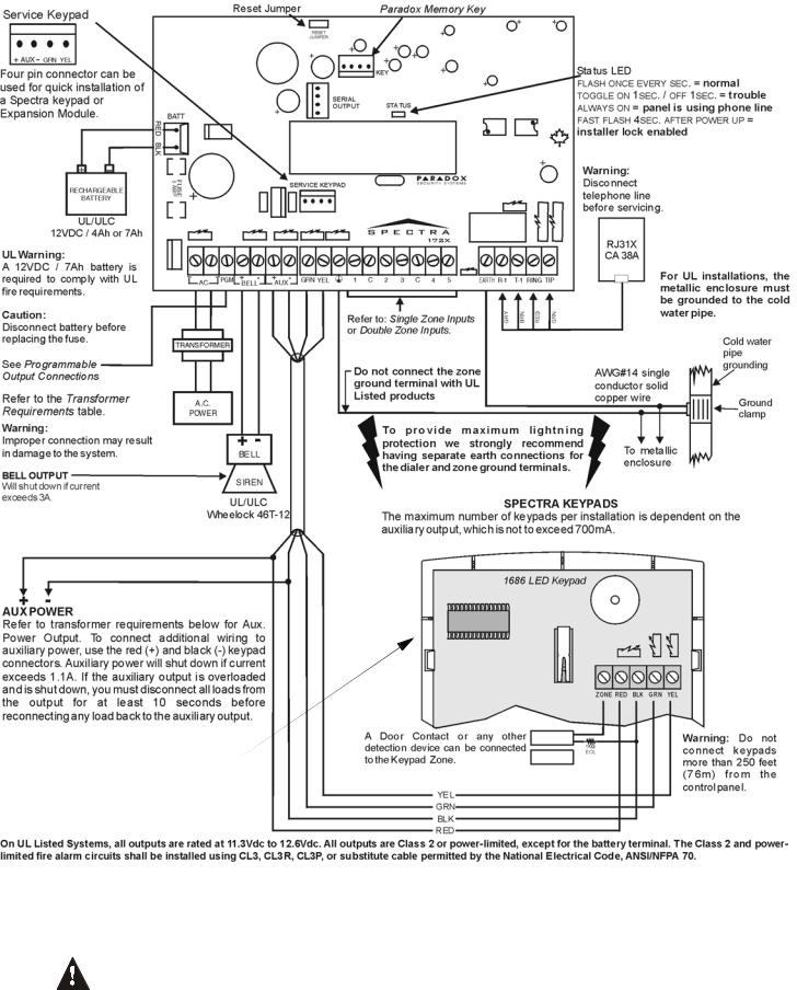
Figure 2.2: Spectra 1728EX and 1728 Control Panel Overview
For the keypad’s zone, EOL and tamper configurations, refer to
Configuring The LED Keypads on page 14.
2.2EARTH GROUND
Connect the zone and dialer ground terminals from the control panel to the metallic enclosure and cold water pipe or grounding rod as per local electrical codes.
For maximum lightning protection, use separate earth grounds for the zone and dialer grounds as shown in Figure 2.1 on page 7. For UL installations, the metallic enclosure must be grounded to the cold water pipe.
8 REFERENCE & INSTALLATION MANUAL
2.3AC POWER
Do not use any switch-controlled outlets to power the transformer. Connect the transformer as shown in Figure 2.1 on page 7. Use Table 1 to determine the required transformer.
Table 1: Transformer Requirements Table
Transformer: |
Amseco XP-1620 16VAC 20VA |
UL: Basler Electric BE156240CAA007 |
|
(Not verified by UL) |
16.5VAC 40VA |
Spectra DC Power Supply rated at: |
1.2A |
1.5A |
Auxiliary Supply can provide a maximum of: |
typ: 600mA, max: 700mA |
typ: 600mA, max: 700mA |
Acceptable Battery Charge Currents |
350mA |
350mA/700mA |
2.4BACKUP BATTERY
In order to provide power during a power loss, connect a 12VDC 4Ah rechargeable acid/lead or gel cell backup battery as shown in Figure 2.1 on page 7. Use a 7Ah battery to comply with UL fire requirements. Connect the backup battery after applying AC power. When installing verify proper polarity as reversed connections will blow the battery fuse. Also, refer to Battery Charge Current on page 43.
2.4.1BATTERY TEST
If the battery is disconnected or if the battery fuse is blown, a No/Low Battery failure will appear in the keypads’ Trouble Display (see page 50). This trouble will also appear if the battery’s capacity is too low or if the voltage drops to 10.5 volts or lower while the control panel is running on the backup battery. At 8.5 volts or lower, the panel shuts down and all outputs close.
2.5AUXILIARY POWER TERMINALS
The auxiliary power supply terminals can be used to power motion detectors, keypads and other modules or accessories in the security system. A fuseless circuit protects the power supply against current overload and automatically shuts down if the current exceeds 1.1A. If this occurs, the Maximum Auxiliary Current failure will appear in the keypads’ Trouble Display (see page 50). Therefore, the combined current consumption of devices connected to the auxiliary power supply should not exceed 700mA. If the auxiliary output is overloaded and is shut down, you must disconnect all loads from the output for at least 10 seconds before reconnecting any load back to the auxiliary output.
Modules with the APRprefix are compatible with Spectra (versions 2.0 and higher) and Digiplex. Modules with the APR3prefix are compatible with Spectra( versions 2.0 and higher), Digiplex and DigiplexNE.
Table 2: Current Consumption Table
Modules |
Current Consumption |
|
|
|
|
|
Typical |
Maximum |
Spectra 1686H and 1686V 10-Zone LED Keypad |
62mA |
116mA |
Spectra 1689 16-Zone LED Keypad |
50mA |
117mA |
Spectra 1641 LCD Keypad |
60mA |
80mA |
Wireless Expansion Bus Module (SPC-319) |
70mA |
70mA |
8-Zone Hardwire Bus Modules (APR3-ZX8) |
30mA |
30mA |
4-PGM Output Bus Module (APR3-PGM4) |
13mA |
150mA |
Printer Bus Module (APR3-PRT1) |
22mA |
40mA |
4-Zone Expansion Bus Module (SPC-ZX4) |
12mA |
12mA |
InTouch Voice-Assisted Arm/Disarm Bus Module (APR3-ADM2) |
70mA |
105mA |
Motion Detectors (see detector instructions for details) |
10 to 50mA |
|
SPECTRA SERIES 9
2.6TELEPHONE LINE CONNECTION
In order to report system events to the central station, you must connect the incoming telephone company wires into the TIP and RING connections of the control panel and then run the wires from T1 and R1 to the telephone or telephone system as shown in Figure 2.1 on page 7.
2.7BELL OUTPUT CONNECTION
The BELL+ and BELLterminals power bells, sirens and other warning devices requiring a steady voltage output during an alarm. The bell output supplies 12VDC upon alarm and can support one 30-watt or two 20-watt sirens. The bell output uses a fuseless circuit and will automatically shut down if the current exceeds 3A. When this occurs the Maximum Bell Current failure will only appear in the keypads’ Trouble Display (see page 50) during an alarm. If the load on the BELL terminals returns to normal, the control panel will re-instate power to the BELL terminals during the next alarm. When connecting sirens, please verify correct polarity. Connect the positive lead to the BELL+ terminal and the negative lead to the BELLterminal of the control panel as shown in Figure 2.1 on page 7.
If the BELL output is not being used, the Bell Disconnected failure will remain in the keypads’ Trouble Display (see page 50). To avoid this connect a 1KΩ resistor across the BELL terminals.
2.8PROGRAMMABLE OUTPUT CONNECTIONS
When a specific event occurs in the system, a PGM can reset smoke detectors, activate strobe lights, open/close garage doors and much more.
2.8.1 PGM FOR 1728EX AND 1728 |
Figure 2.3: PGM |
The Spectra 1728/EX control panels include one on-board programmable output (PGM). PGM1 provides a maximum 150mA output. If the current draw on the PGM is to exceed the current output, we recommend the use of a relay as shown in Figure 2-2. For details on how to program the PGM, refer to PGM Programming on page 41.
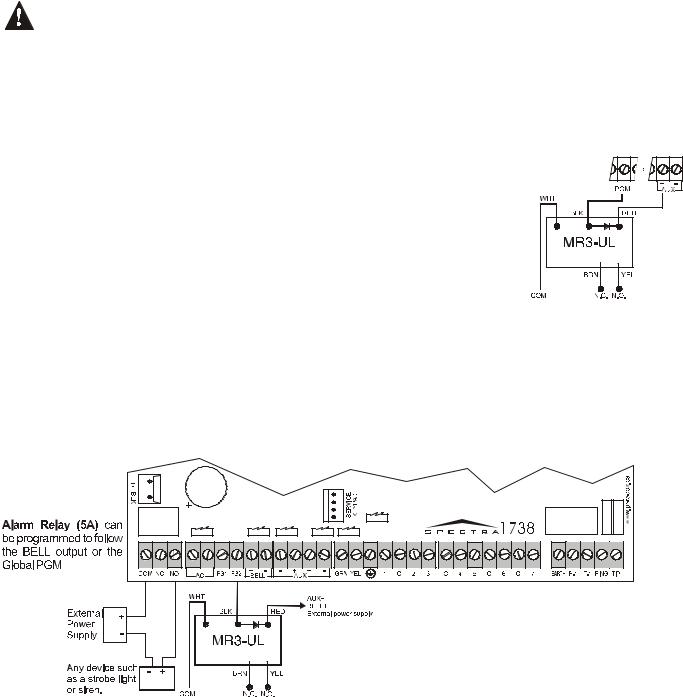
2.8.2 ALARM RELAY AND PGMS FOR 1738EX AND 1738
The Spectra 1738/EX control panels include two on-board programmable outputs (PGMs). PGM1 and PGM2 provide up to 1A and PGM2 can be used as a strobe output
(see page 42). The PGMs are limited by the power source being used. If powered by the BELL+ terminal, the combined current consumption of the bell output and PGM must not exceed 1A. If it is powered by the AUX+, the devices connected to the auxiliary power
supply and PGM must not exceed 1.1A. If it is powered by an external device, PGMs can supply 1A. If the current draw on the PGM is to exceed the current output, we recommend using a relay (see Figure 2.4). For details on how to program the PGM, refer to PGM Programming on page 41.
The Spectra 1738/EX control panels also have an optional 5A relay. This relay can be connected as shown in Figure 2.4. The Alarm Relay can be programmed to follow the bell output or the activation and deactivation of the Global PGM (see Alarm Relay Options on page 42).
Figure 2.4: Relay and PGM Connections
10 REFERENCE & INSTALLATION MANUAL
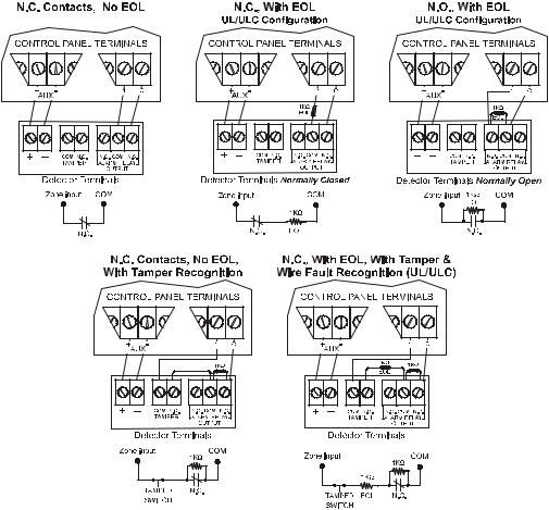
2.9SINGLE ZONE INPUTS
Detection devices such as motion detectors and door contacts are connected to the control panel's zone input terminals. Figure 2.5 on page 11 demonstrates single zone input terminal connections recognized by Spectra. Once connected, the associated zone's parameters must be defined. For details refer to Zone Programming on page 19.
Figure 2.5: Single Zone Input Connections
2.10 DOUBLE ZONE INPUTS (WITH ATZ OPTION ONLY)
Enabling the ATZ feature (see page 25) on the Spectra 1728 or 1738 allows you to install two detection devices per input terminal. The ATZ feature is a software oriented feature. Therefore, there is no need for extra modules. Simply connect the devices as shown in Figure 2.6. Devices connected to input terminals must be assigned to a zone and the zone's parameters must be defined. Refer to Zone Programming on page 19 for more information. The status of each zone will be displayed on the keypads and the control panel can send separate alarm codes for each zone.
SPECTRA SERIES 11
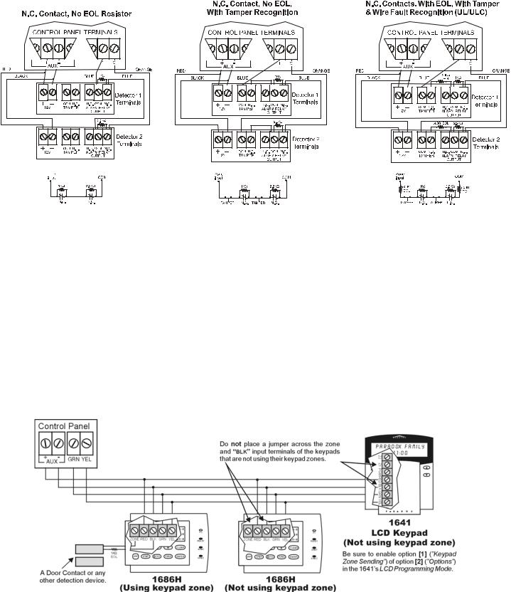
Figure 2.6: Double Zone (ATZ) Input Connections
2.11 KEYPAD AND KEYPAD ZONE CONNECTIONS
To connect the keypads to the control panel, remove the back cover and wire the GRN, YEL, RED, and BLK terminals of each keypad to the corresponding terminals on the control panel as shown in Figure 2.1 on page 7 or Figure 2.2 on page 8. There is no limit to the number of keypads that can be connected to the control panel so long as the current consumption does not surpass 700mA. For details on Keypad Tamper Supervision see section 10.8 on page 44.
Each keypad has one zone input terminal, allowing you to connect one motion detector or door contact directly to a keypad. The keypad can then communicate the status of the zone to the control panel. A maximum of two keypad zones can be used with each control panel. After connecting the device, the zone's parameters must be defined. For details on zone recognition and Zone Programming refer to page 19. Also, refer to the feature Reassign Keypad Zone 2 on page 19.
Example: A door contact located at the entry point of an establishment can be wired directly to the input terminal of the entry point keypad instead of wiring the door contact all the way to the control panel.
Figure 2.7: Keypad Zone Connections
12 REFERENCE & INSTALLATION MANUAL
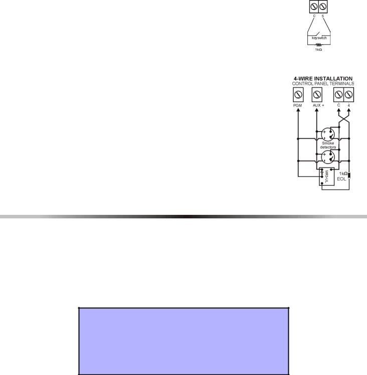
2.12 KEYSWITCH CONNECTIONS |
Figure 2.8: Keyswitch |
Keyswitches allow users to arm or disarm a partition by pushing a button or by activating a switch with a key. Connect the keyswitch as shown in Figure 2.8 directly to the control panel terminals. Once a keyswitch is connected, it must be assigned to a zone and its parameters must be programmed (see Zone Programming on page 19 and Keyswitch Options on page 25).
2.13 FIRE CIRCUITS
When a zone is programmed as a Fire zone, the zone becomes normally open and |
Figure 2.9: Fire Zones |
requires an EOL resistor. If a line short occurs or if the smoke detector becomes |
|
active, whether the system is armed or disarmed, the control panel will generate an |
|
alarm. If a trouble occurs on a Fire zone, the Fire Loop Trouble will appear in the |
|
keypads’ Trouble Display (see page 50) and the control panel can transmit the Fire |
|
Loop Trouble report, if programmed, in section [206]. |
|
2.13.1 4-WIRE INSTALLATION: |
|
Any on-board zone can be defined as a Fire Zone (see page 21) when |
|
using the 4-wire installation. Connect the smoke detectors as shown in |
|
Figure 2.9 directly to the control panel terminals. Program the PGM with the |
|
“[PG]/[FNC1] Key was Pressed” Activation Event (see page 41) so the |
|
smoke detectors can be reset by pressing the [PG] or [FNC1] key. Pressing |
|
the [PG] or [FNC1] key will interrupt power to the smoke detectors for 4 |
|
seconds (see PGM Delay on page 42). |
|
PART 3: PROGRAMMING METHODS
3.1WINLOAD SOFTWARE FOR WINDOWS
Program the Spectra Series control panels remotely or on-site using the Winload Software for Windows®. For more information, contact your local Paradox Distributor or visit our web site at http://www.paradox.ca. If you are using the WinLoad software, you must program the features explained on pages 48 and 49.
3.2PROGRAMMING USING A KEYPAD
Use the supplied Spectra 1728EX, 1728, 1738EX and 1738 Programming Guide to keep track of which sections were programmed and how. We recommend you read this entire manual before you begin programming.
How Do I Enter Programming Mode?
STEP 1: Press [ENTER]
STEP 2: Enter your [INSTALLER CODE] (default: 000000 or 0000)
STEP 3: Enter 3-digit [SECTION] you wish to program
STEP 4: Enter required [DATA]
3.2.1SINGLE DIGIT DATA ENTRY METHOD (HEXADECIMAL AND DECIMAL)
Single Digit Data Entry is used in all sections except those specified in the Feature Select Programming Method. After entering the programming mode as described in the shaded box above, some sections will require that you enter Decimal values from 000 to 255. Other sections will require that you enter Hexadecimal values from 0 to F. The required data will be clearly indicated in this manual as well as in the
Spectra 1728EX, 1728, 1738EX and 1738 Programming Guide. When entering the final digit in a section, the control panel will automatically save and advance to the next section. Except sections 001 to 016, after entering the first two digits the control panel will switch to Feature Select Programming.
SPECTRA SERIES 13
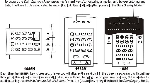
Table 3: Decimal and Hexadecimal Programming Table
Value or Action |
What Do I |
|
What Do I See? |
|
|
Press? |
|
|
|
|
|
10-Zone LED |
16-Zone LED |
LCD |
|
||
|
|
||||
|
|
|
|
|
|
Values 1 to 9 |
[1] to [9] |
[1] to [9] |
[1] to [9] |
[1] to [9] |
|
A (hexa only) |
[0] |
[0 (10)] |
[10] |
0 |
|
B (hexa only) |
[STAY] |
[STAY] |
[11] |
B |
|
|
|
|
|
|
|
C (hexa only) |
[BYP] |
[BYP] |
[12] |
C |
|
|
|
|
|
|
|
D (hexa only) |
[MEM] |
[MEM] |
[13] |
D |
|
|
|
|
|
|
|
E (hexa only) |
[TBL] / [TRBL] |
[TBL] |
[14] |
E |
|
|
|
|
|
|
|
F (hexa only) |
[PG] / [FNC1] |
[PG] |
[15] |
F |
|
Exit Without Saving |
[CLEAR] |
[ENTER] flashes |
[ARM1] & [STAY1] flash |
“SECTION [ |
]” |
|
|
|
|
|
|
Insert Blank Digit |
[FORCE] |
Displays next digit |
or next section |
|
|
|
|
|
|
|
|
Save Data |
[ENTER] |
Advances to the next section |
|
|
|
|
|
|
|
|
|
3.2.2FEATURE SELECT PROGRAMMING METHOD
After entering sections [001] to [016], [126] to [138], and [302] to [348], each option from [1] to [8] represents a specific feature or option. Press the key corresponding to the desired option and the corresponding light will illuminate or the option number will appear in the LCD display. This means the option is on. Press the key again to extinguish the corresponding light or remove the digit from the LCD display, thereby, turning off the option. Press the [FORCE] key to set all 8 options to off. Press the keys until the current section’s options are set. When the options are set, press the [ENTER] key to save and advance to the next section.
3.2.3DATA DISPLAY MODE (LED KEYPADS ONLY)
In the Data Display Mode you can view the programmed contents of each section one digit at a time. After entering the desired 3-digit section (see step 3 of the shaded box on page 13), press the [ENTER] key to access the Data Display Mode (will not function with sections using Multiple Feature Select Programming).
Figure 3.1: Data Display Mode (LED Keypads Only)
3.3CONFIGURING THE LED KEYPADS
Depending on the version of the keypad, two methods can be used to configure the LED keypads (1686H, 1686V and 1689):
14 REFERENCE & INSTALLATION MANUAL

3.3.1CONFIGURING THE 1686H, 1686V AND 1689 KEYPADS V2.0 OR HIGHER
The keypad’s zone number, EOL definition and tamper switch are programmed through the control panel’s programming mode. To do so:
How Do I Configure The Keypad?
STEP 1: Press
STEP 2: Enter your [INSTALLER CODE] (default: 000000 or 0000)
STEP 3: Press the [PG] (1686H/V) / [FNC1] (1689) key and hold it for 3 seconds.
STEP 4: Press the desired key ([1] to [3]. See below)
STEP 5: Press [ENTER] to exit programming mode
 PLEASE NOTE: After two minutes, the keypad exits programming mode.
Key [1] - Keypad Zone Selection
Key [1] determines whether the keypad’s zone is Keypad Zone 1 or Keypad Zone 2. When key [1] is OFF (not illuminated), the keypad’s zone is Keypad Zone 1. When key [1] is ON (illuminated), the keypad’s zone is Keypad Zone 2.
Key [1] OFF - Keypad Zone 1 (default) Key [1] ON - Keypad Zone 2
Key [2] - EOL Definition
Key [2] determines the keypad zone’s EOL definition. When key [2] is OFF (not illuminated), EOL is disabled and the keypad zone will use the on-board EOL resistor. When key [2] is ON (illuminated), EOL is enabled and the keypad zone requires that an external EOL resistor be connected (refer to Spectra 1738EX and 1738 Control Panel Overview on page 7 and Spectra 1728EX and 1728 Control Panel Overview on page 8 for more details).
Key [2] OFF - EOL disabled
Key [2] ON - EOL enabled (default)
Key [3] - On-Board Tamper
Key [3] enables or disables the keypad’s on-board tamper switch. When key [3] is OFF (not illuminated), the tamper switch is disabled. When key [3] is ON (illuminated), the tamper switch is enabled.
Key [3] OFF - On-board tamper switch disabled Key [3] ON - On-board tamper switch enabled
PLEASE NOTE: The keypad can be ordered with or without a tamper switch. If the keypad has no tamper switch, key [3] will be OFF by default. If the keypad has a tamper switch, key [3] will be ON by default.
3.3.2CONFIGURING THE 1686H, 1686V AND 1689 KEYPADS PRIOR TO V2.0
The keypad’s zone number and EOL definition are defined through the jumpers located on the PCB board. The jumpers are as follows:
J1 - Keypad Zone Select Jumper
Jumper J1 determines whether the keypad’s zone is Keypad Zone 1 or Keypad Zone 2. When the jumper is OFF, the keypad’s zone is Keypad Zone 2. When the jumper is ON, the keypad’s zone is Keypad Zone 1.
J1 OFF - Keypad Zone 2
J1 ON - Keypad Zone 1
SPECTRA SERIES 15
J2 - EOL Definition Jumper
Jumper J2 determines the keypad zone’s EOL definition. When the jumper is OFF, EOL is disabled and the keypad zone uses the on-board EOL resistor. When the jumper is ON, EOL is enabled and the keypad zone requires that an external EOL resistor be connected (refer to Spectra 1738EX and 1738 Control Panel Overview on page 7 and Spectra 1728EX and 1728 Control Panel Overview on page 8 for more details).
J2 OFF - EOL disabled
J2 ON - EOL enabled
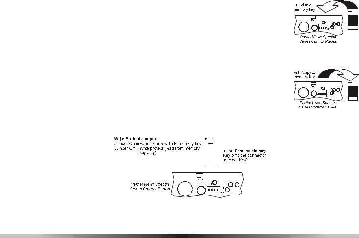
3.4PROGRAMMING USING A PARADOX MEMORY KEY
Copy the sections of one Spectra control panel into the Paradox Memory Key (PMC-3). Then copy the contents of the Memory Key into as many Spectra control panels as needed. Each panel is programmed in less than 3 seconds.
Download to DESTINATION Control Panel
1) Remove AC and battery power from the control panel. 2) Place the Memory Key on the serial connector labeled KEY of the Spectra Control Panel
that is to receive the contents of the Memory Key.
3) Reapply AC and battery power. 4) In installer programming mode, enter section [900], then press [ENTER] to acknowledge.
5)When the keypad emits a Confirmation Beep, remove the Memory Key.
6)Enter section [750] to reprogram the modules with the information downloaded from the Paradox Memory Key.
Copy to Memory Key from SOURCE Control Panel
1) Remove AC and battery power from the control panel.
2) Place Memory Key on the serial connector labeled KEY of the Spectra Control Panel that you want to copy. Make sure the write protect jumper of the Memory Key is on.
3) Reapply AC and battery power.
4) In installer programming mode, enter section [902], then press [ENTER] to acknowledge.
5)When the keypad emits a Confirmation Beep, remove the Memory Key. Remove the Memory Key’s jumper if you do not wish to accidentally overwrite its contents.
Figure 3.2: Paradox Memory Key
|
|
|
|
|
|
|
|
|
|
|
|
|
|
|
|
|
|
|
|
|
|
|
|
|
|
|
|
|
|
|
|
|
|
|
|
|
|
|
|
|
|
|
|
|
|
|
|
|
|
|
|
|
|
|
|
|
|
|
|
|
|
|
|
|
|
|
|
|
|
|
|
|
|
|
|
|
|
|
|
|
PART 4: ACCESS CODES |
||||||||
The Spectra Series control panels support the following access |
|
codes: |
|||||||
|
|||||||||
|
|
|
|
|
|
|
|
||
INSTALLER CODE: |
|
Used to program all control panel settings except User Access Codes. |
|||||||
SYSTEM MASTER CODE (001) |
|
Provides full access. Arm and disarm using any method described in the User Code |
|||||||
|
|
Options in section 4.4 as well as program the User Access Codes. |
|||||||
|
|
|
|
|
|
|
|
||
Master Code 1 (002): |
|
Permanently assigned to partition 1. Same as a regular User Code except it can |
|||||||
|
|
also program access codes for User Codes assigned to partition 1. |
|||||||
|
|
|
|
|
|
|
|
||
Master Code 2 (003): |
|
Permanently assigned to partition 2. Same as a regular User Code except it can |
|||||||
|
|
program access codes for User Codes assigned to partition 2. If the system is not |
|||||||
|
|
partitioned Master Code 002 will be assigned to partition 1. |
|||||||
|
|
|
|
|
|
|
|
||
45 User Codes (004 to 048): |
|
Can arm and disarm as per User Code Options in section 4.4. |
|||||||
16 REFERENCE & INSTALLATION MANUAL

4.1ACCESS CODE LENGTH
Section [127]: System Options
Option [2] |
OFF |
= 6-Digit Access Codes |
Option [2] |
ON |
= 4-Digit Access Codes (default) |
All access codes can be set to lengths of either 4- or 6-digits. When the 4-digit option is selected, entering a 4-digit code will allow access. Using the 6-digit option, entering 6 digits is required to allow access.
If the Access Code Length is changed from four digits to six digits when access codes have already been programmed, the control panel will automatically add the last 2 digits by using the first 2 digits. For example, if the access code is 1234 and you switch to 6 digits, the code will become 123412. Be sure to verify the access codes after switching from 4-digit access codes to 6-digit codes. When switching from six digits to four digits, the control panel will simply remove the final two digits of the access code. For example, 123456 will become 1234.
4.2INSTALLER CODE (Default: 000000 OR 0000)
The Installer Code is used to enter the control panel's programming mode (see page 13), which allows you to program all the features, options and commands of the control panel. The Installer Code can be 4- or 6-digits in length (see above) where each digit can be any value from 0 to 9. The Installer Code cannot be used to program
Master Code 1, Master Code 2 or User Access Codes. To program the Installer Code press: [ENTER] + [CURRENT INSTALLER CODE] + [281] + new 4- or 6-digit Installer Code
4.3SYSTEM MASTER CODE (Default: 123456 OR 1234)
The Installer Code can be used to program the System Master Code. With the System Master Code a user can use any arming method and can program any User Access Code, but not the User Code Options. The System Master Code can be 4 or 6 digits in length (see section 4.1), where each digit can be any digit from 0 to 9. To change the
System Master Code press:
[ENTER] + [INSTALLER CODE] + [301] + new 4- or 6-digit System Master Code
4.4USER CODE OPTIONS
Sections [302] to [348]: Options [1] to [7]
The User Code Options define which arming methods each user can use to arm or disarm the system. Regardless of these settings, all users can Regular Arm assigned partitions and all users except those with the Arm Only option can disarm an assigned partition, regardless of how it is armed. Select one or more of the options described on the following pages for each User Access Code, where sections [302] to [348] represent User Access Codes 002 to 048. For information on how User Access Codes are programmed, please refer to page 51.
4.4.1PARTITION 1 ASSIGNMENT
Sections [302] to [348]: User Codes 002 to 048
Option [1] |
OFF |
= Deny access to partition 1 |
Option [1] |
ON |
= User code has access to partition 1 (default) |
If Partitioned (see page 43), user codes with this option enabled can arm and disarm partition 1.
If the system is not partitioned, you must assign partition 1 to the User Access Code. Otherwise, the User Access Code will be considered disabled.
4.4.2PARTITION 2 ASSIGNMENT
Sections [302] to [348]: User Codes 002 to 048
Option [2] |
OFF |
= Deny access to partition 2 (default) |
Option [2] |
ON |
= User code has access to partition 2 |
If the system is partitioned (see page 43), user codes with this option enabled can arm and disarm partition 2. If the system is not partitioned, the control panel ignores this option.
SPECTRA SERIES 17
4.4.3BYPASS PROGRAMMING
Sections [302] to [348]: User Codes 002 to 048
Option [3] OFF |
= Bypass Programming Disabled |
Option [3] ON |
= Bypass Programming Enabled (default) |
User codes with this option enabled can perform Bypass Programming in assigned partitions.
4.4.4STAY ARMING
Sections [302] to [348]: User Codes 002 to 048
Option [4] OFF |
= Stay Arming Disabled |
Option [4] ON |
= Stay Arming Enabled for selected User Code (default) |
User codes with this option enabled can Stay Arm assigned partitions.
4.4.5FORCE ARMING
Sections [302] to [348]: User Codes 002 to 048
Option [5] |
OFF |
= Force Arming Disabled (default) |
Option [5] |
ON |
= Force Arming Enabled for selected User Code |
User codes with this option enabled can Force Arm assigned partitions.
4.4.6ARM ONLY
Sections [302] to [348]: User Codes 002 to 048
Option [6] |
OFF |
= Arm Only Disabled (default) |
Option [6] |
ON |
= Arm Only Enabled for selected User Code |
The user code with this option enabled can arm assigned partitions, but cannot disarm any partitions. The type of arming is dependent on the other User Code Options selected. Please note that with the Arm Only option, the user can cancel a recently armed system by re-entering the access code before the end of the
Exit Delay.
4.4.7PGM ACTIVATION
Sections [302] to [348]: User Codes 002 to 048
Option [7] OFF |
= User Code follows User Code Options and can activate a PGM (default) |
Option [7] ON |
= User Code can activate a PGM only |
With option [7] off, entering the access code will arm or disarm according to the programmed User Code Options as well as activate or deactivate a PGM. The appropriate PGM Activation/Deactivation Event must also be programmed (see page 41). With option [7] on, the control panel will ignore all other User Code Options. Therefore, entering the access code will only activate or deactivate the PGM.
4.5LOCK MASTER CODE
Section [127]: System Options
Option [4] |
OFF |
= Lock System Master Code Disabled (default) |
Option [4] |
ON |
= Lock System Master Code Enabled |
With this feature enabled, the control panel will lock the System Master Code (001). This means that the System Master Code cannot be deleted, but it can be changed.
4.6DURESS CODE
Section [127] = System Options
Option [6] |
OFF |
= Duress Code Disabled (default) |
Option [6] |
ON |
= User Code 048 becomes a Duress code |
With this feature enabled, User Code 048 becomes a Duress Code. When forced to arm or disarm their system, users can enter a Duress Code (User Code 048) to arm or disarm the system which can immediately transmit a silent alert to the Central Station, transmitting the duress report code programmed in section [196].
18 REFERENCE & INSTALLATION MANUAL
 Loading...