


 Loading...
Sony VPL-PX35, VPL-CX76, VPL-CX85, VPL CX75, VPL-FX51 User Manual
...DATA PROJECTOR
VPL-CX75 VPL-CX76 VPL-CX85
VPL-CX86
VPL-FX51 VPL-FX52 VPL-FX52L VPL-PX35 VPL-PX40 VPL-PX41
PROTOCOL MANUAL 1st Edition (Revised 7)

! WARNING
This manual is intended for qualified service personnel only.
To reduce the risk of electric shock, fire or injury, do not perform any servicing other than that contained in the operating instructions unless you are qualified to do so. Refer all servicing to qualified service personnel.
! WARNUNG
Die Anleitung ist nur für qualifiziertes Fachpersonal bestimmt.
Alle Wartungsarbeiten dürfen nur von qualifiziertem Fachpersonal ausgeführt werden. Um die Gefahr eines elektrischen Schlages, Feuergefahr und Verletzungen zu vermeiden, sind bei Wartungsarbeiten strikt die Angaben in der Anleitung zu befolgen. Andere als die angegeben Wartungsarbeiten dürfen nur von Personen ausgeführt werden, die eine spezielle Befähigung dazu besitzen.
! AVERTISSEMENT
Ce manual est destiné uniquement aux personnes compétentes en charge de l’entretien. Afin de réduire les risques de décharge électrique, d’incendie ou de blessure n’effectuer que les réparations indiquées dans le mode d’emploi à moins d’être qualifié pour en effectuer d’autres. Pour toute réparation faire appel à une personne compétente uniquement.
VPL-CX75/CX76/CX85/CX86/FX51/FX52/FX52L/PX35/PX40/PX41
Table of Contents
1.Introduction
2.RS-232C (VPL-CX75 and VPL-CX76 are excluded.)
2-1. |
Communication Specifications .......................................... |
1 |
|
2-2. |
Command Block Format .................................................... |
2 |
|
2-3. |
Block Format ..................................................................... |
3 |
|
2-4. |
Connection ......................................................................... |
4 |
|
2-5. |
Communication Procedure ................................................ |
4 |
|
2-5-1. |
Outline of Communication ....................................... |
4 |
|
2-6. |
Communication Rules ....................................................... |
5 |
|
2-7. |
Approximate Return Waiting Times ................................. |
5 |
|
3. |
NETWORK |
|
|
3-1. |
Introduction ........................................................................ |
6 |
|
3-1-1. |
Advertisement .......................................................... |
6 |
|
|
3-1-1-1. Function ................................................................. |
6 |
|
|
3-1-1-2. |
Setup Items ............................................................ |
6 |
3-1-2. |
Remote Control ........................................................ |
7 |
|
|
3-1-2-1. Function ................................................................. |
7 |
|
|
3-1-2-2. |
Setup Items ............................................................ |
7 |
3-2. |
SDAP Protocol ................................................................... |
8 |
|
3-3. |
SDCP Protocol ................................................................... |
9 |
|
3-3-1. |
Format ...................................................................... |
9 |
|
|
3-3-1-1. Header ................................................................... |
9 |
|
|
3-3-1-2. Community ............................................................ |
9 |
|
|
3-3-1-3. Command ............................................................ |
10 |
|
|
3-3-1-4. |
SET Request ........................................................ |
11 |
|
3-3-1-5. |
GET Request ....................................................... |
11 |
|
3-3-1-6. |
ERROR Response ............................................... |
11 |
3-3-2. |
Items ....................................................................... |
12 |
|
|
3-3-2-1. |
Model Dependent Category ................................ |
12 |
|
3-3-2-2. Equipment Information Acquisition (80**h) ...... |
12 |
|
|
3-3-2-3. Network Information Acquisition (90**h) ......... |
13 |
|
3-3-3. |
Error Code .............................................................. |
14 |
|
|
3-3-3-1. |
Item Error ............................................................ |
15 |
|
3-3-3-2. |
Community Error ................................................ |
15 |
|
3-3-3-3. |
Request Error ...................................................... |
16 |
|
3-3-3-4. |
Network Error ..................................................... |
16 |
|
3-3-3-5. |
Comm Error ........................................................ |
17 |
|
3-3-3-6. |
NVRAM Error .................................................... |
17 |
Appendix A.
Setup Method For VPL-PX35 and PX40
A-1. |
Command ......................................................................... |
18 |
|
A-1-1. |
Setting ..................................................................... |
18 |
|
A-1-2. |
Display ................................................................... |
19 |
|
A-2. |
Setting Command ............................................................ |
20 |
|
Appendix B
VPL-CX75/CX76/CX85/CX86/FX51/FX52/FX52L/PX35/PX40/PX41 |
1 |

1. Introduction
This protocol manual describes the basic configuration and basic operations of various commands used for projector. Projector can be controlled using the commands provided in “Appendix”. Using an external CONTROLLER , etc., inputs can be switched and the power can also be turned on and off. In the following paragraphs, “CONTROLLER” means an external device such as a PC which controls projector using these commands.
2. RS-232C (VPL-CX75 and VPL-CX76 are excluded.)
2-1. Communication Specifications
<RS-232C Communication Signal>
. Full duplex communication channels (Flow control not performed.)
. Start-stop synchronism system
. Baud rate: 38.4 kbps (bits per second)
. The bit configuration is defined as follows.
1 START Bit + 8 DATA Bits + 1 PARITY Bit + 1 STOP Bit
START |
D0 |
D1 |
D2 |
D3 |
D4 |
D5 |
D6 |
D7 |
PARITY |
STOP |
BIT |
(LSB) |
|
|
|
|
|
|
(MSB) |
(EVEN) |
BIT |
EVEN Parity.....Total number of “1”s from D0 to D7 is an even number.
VPL-CX75/CX76/CX85/CX86/FX51/FX52/FX52L/PX35/PX40/PX41 |
1 |

2-2. Command Block Format
The code from B0 to B7 as described below are transmitted.
B0
B1
B2
B3
B4
B5
B6
B7
Transmission from |
Reception in |
Reception in the Master side |
the Master side |
the Master side |
(With Data) |
|
|
|
|
|
|
|
START CODE : 0 x A9 |
|
ITEM NUMBER |
ACK / NAK |
ITEM NUMBER |
|
|
|
SET / GET |
ACK |
REPLY |
|
|
|
DATA |
DUMMY DATA |
DATA |
|
|
|
|
CHECK SUM |
|
|
|
|
|
END CODE : 0 x 9A |
|
B0 |
START CORD |
|
|
|
|
|
|
Common in the all FORMAT |
|
|
|
|
|
B6 |
CHECK SUM |
|
|
|
|
|
|
B1 to B5 are calculated by OR; |
|
|
|
|
|
|
<Example of Calculation> |
|
|
|
|
|
|
0 x A9 |
1010 |
1001 |
0 x A9 |
1010 |
1001 |
|
0 x A9 |
1010 |
1001 |
0 x 9A |
1001 |
1010 |
|
Answer |
1010 |
1001 |
Answer |
1011 |
1011 |
|
|
|
0 x A9 |
|
|
0 x BB |
B7 |
END CODE |
|
|
|
|
|
|
Common in the all FORMAT |
|
|
|
|
|
2 |
VPL-CX75/CX76/CX85/CX86/FX51/FX52/FX52L/PX35/PX40/PX41 |
2-3. |
|
Block Format |
|
|
|
|
|
Transmission from the Master side |
|
|
|
|
|
|
B0 |
|
START CODE |
B1 |
|
ITEM NUMBER |
|
|
|
B2 |
|
|
|
|
|
|
|
|
B3 |
|
SET / GET |
|
|
|
B4 |
|
DATA |
|
|
|
B5 |
|
|
|
|
|
|
|
|
B6 |
|
CHECK SUM |
|
|
|
B7 |
|
END CODE |
|
|
|
|
|
|
|
|
Reception in the Master side |
|
|
|
|
|
|
B0 |
|
START CODE |
B1 |
|
ACK / NAK |
|
|
|
B2 |
|
|
|
|
|
|
|
|
B3 |
|
ACK |
|
|
|
B4 |
|
DUMMY DATA |
|
|
|
B5 |
|
|
|
|
|
B6 |
|
CHECK SUM |
|
|
|
B7 |
|
END CODE |
|
|
|
|
|
|
|
|
Reception in the Master side (With Data) |
|
|
|
|
|
|
B0 |
|
START CODE |
B1 |
|
ITEM NUMBER |
|
|
|
B2 |
|
|
|
|
|
|
|
|
B3 |
|
REPLY |
|
|
|
B4 |
|
DATA |
|
|
|
B5 |
|
|
|
|
|
B6 |
|
CHECK SUM |
|
|
|
B7 |
|
END CODE |
|
|
|
Data transmission to the Projector
Start of Command
Set the Data Category Value desired.
Refer to the Appendix B Table 1 for details.
SET: 0 x 00 (Set data)
GET: 0 x 01 (Get data)
SET: Data to be set (Refer to the Appendix B Table 2) GET: Unused. Set Dummy data [0 x 00, 0 x 00]
Check Sum
End of Command
Receive results of the data transmission from the Projector.
Start of Command
Results correspond with the data transmission
Refer to the Appendix B Table 3 for the data in detail.
[0 x 03]
Express Reply data either of ACK, or NAK
This data does not mean any senses.
Dummy Data [0 x 00, 0 x 00] is stored.
Check Sum
End of Command
Receive data from the Projector
Start of Command
Data to acquire
Refer to the Appendix B Table 1 in detail.
[0 x 02]
Express data to be Reply data
Received data
Refer to the Appendix B Table 2 in detail.
Check Sum
End of Command
VPL-CX75/CX76/CX85/CX86/FX51/FX52/FX52L/PX35/PX40/PX41 |
3 |
2-4. Connection
<RS-232C Connection>
Communication is enabled by the use of a D-Sub 9 Pin cross (reverse) cable.
The pin assignment of D-Sub 9 Pin and D-Sub 25 Pin is as follows.
D-Sub 9 Pin |
D-Sub 25 Pin |
|
Name |
Shell = FG |
1 |
FG |
Grounding for safety protection or cable shield |
3 |
2 |
TxD |
Transmission data |
2 |
3 |
RxD |
Reception data |
7 |
4 |
RTS |
Transmission request |
8 |
5 |
CTS |
Transmission permission |
6 |
6 |
DSR |
Data set ready |
5 |
7 |
SG |
GND for signal |
1 |
8 |
DCD |
Data channel signal carrier detection |
4 |
20 |
DTR |
Data terminal ready |
9 |
22 |
RI |
Calling display (Presence/absence of calling signal) |
Pins indicated as D-Sub 25 Pin are not used.
Assured cable length: 15 m (However, assurance may not be applicable for some cables.)
The software for controlling the projector from a PC is intended for performing transmission and reception for only the TxD and RxD lines.
Therefore there is no handshake normally performed by RS-232C.
2-5. Communication Procedure
2-5-1. Outline of Communication
All communication between CONTROLLER (PC, etc.) and DEVICE (PROJECTOR) is performed by the command block format. Communication is started by the issue of a command at CONTROLLER and ended when the return Data is sent to CONTROLLER after DEVICE receives the command. CONTROLLER is prohibited from sending several commands at one time. This means that after CONTROLLER sends one command, it cannot send other commands until DEVICE returns the return Data. DEVICE sends the return Data after processing the command. The time from when CONTROLLER sends the command until the return Data is returned differs according to the contents of the command.
n
When Sircs Direct Command is sent, return Data may not be returned in some cases.
4 |
VPL-CX75/CX76/CX85/CX86/FX51/FX52/FX52L/PX35/PX40/PX41 |
2-6. Communication Rules
.When sending a command from CONTROLLER, the return Data from PROJECTOR should be received first before sending the next command. Even if the next command is sent before receiving the return Data, since PROJECTOR will not be able to receive that command, it does not return a response to CONTROLLER. Consequently, no error code is also sent.
The following lists the approximate waiting times for PROJECTOR to return the return Data after CONTROLLER sends the command.
.When a communication error occurs, PROJECTOR ignores the Data received until now, and set into the reception standby state.
.For undefined commands or commends determined as invalid by PROJECTOR, PROJECTOR will send the “NAK” return Data to CONTROLLER .
.Take note that when Data is written when the input signal of PROJECTOR is unstable, that Data (value) will not be incorporated.
.When INDEX specified SIRCS direct command is transmitted, leave an interval of 45 msec until the next transmission. (Do not return the return Data (ACK, NAK) when the SIRCS direct command is received.)
2-7. Approximate Return Waiting Times
The await-return time is approx. 30 msec.
n
This is the case, unless the communications are interfered anyway.
VPL-CX75/CX76/CX85/CX86/FX51/FX52/FX52L/PX35/PX40/PX41 |
5 |
3.NETWORK
3-1. Introduction
This section describes the specifications, performance and operations of the network service that is going to be installed in the target projector.
3-1-1. Advertisement
The advertisement service is provided to facilitate development of a PC application that can automatically detect a projector on the network. This function is achieved by broadcasting the equipment information periodically to the network.
3-1-1-1. Function
The equipment information shown below is transmitted as the broadcast packet periodically (at certain intervals).
Information |
Description |
|
|
Category |
Category of the equipment |
|
|
Equipment name |
Name of the equipment |
|
|
Serial number |
Serial number of the equipment |
|
|
Installation information |
Installation location of the equipment |
|
|
Community |
Community name of the equipment |
|
|
Power status |
Power status of the equipment |
|
|
m
. The category of projector is 0x0a.
. The power status sets ffffh if communication error occurs.
Protocol
The SDAP protocol is defined in order to provide this service.
Item |
Description |
|
|
Protocol name |
SDAP (Simple Display Advertisement Protocol) |
|
|
Transport |
UDP |
|
|
Port number |
53862 |
|
|
BC interval |
Once every 30 seconds (initial value) |
|
|
3-1-1-2. Setup Items
The items that can be set for the advertisement service are described below.
Setup items |
Description |
|
|
Port |
Port number |
|
|
Interval |
Broadcast interval |
|
|
6 |
VPL-CX75/CX76/CX85/CX86/FX51/FX52/FX52L/PX35/PX40/PX41 |
3-1-2. Remote Control
The remote control service is provided that can control the target equipment from remote location via network. The SDCP protocol that serves to acquire the basic information such as equipment name and serial numbers is installed in this projector.
3-1-2-1. Function
This responds to the control command and requests for acquiring the status and information supplied from clients.
Control request
Enables the input to be selected and picture control to be adjusted.
SIRCS request
Enables remote control by sending the SIRCS code.
Status request
Enables equipment status information such as power status, error information and power-on time to be acquired.
Information request
Enables equipment information such as equipment name, serial number and installation information to be acquired.
Protocol
Item |
Description |
|
|
Protocol name |
SDCP (Simple Display Control Protocol) |
|
|
Transport |
TCP |
|
|
Port number |
53484 |
|
|
TCP connection timeout |
30 seconds |
|
|
3-1-2-2. Setup Items
The items that can be set for the remote control service are described below.
Setup item |
Description |
|
|
Port |
Port number |
|
|
Timeout |
TCP connection timeout time |
|
|
VPL-CX75/CX76/CX85/CX86/FX51/FX52/FX52L/PX35/PX40/PX41 |
7 |
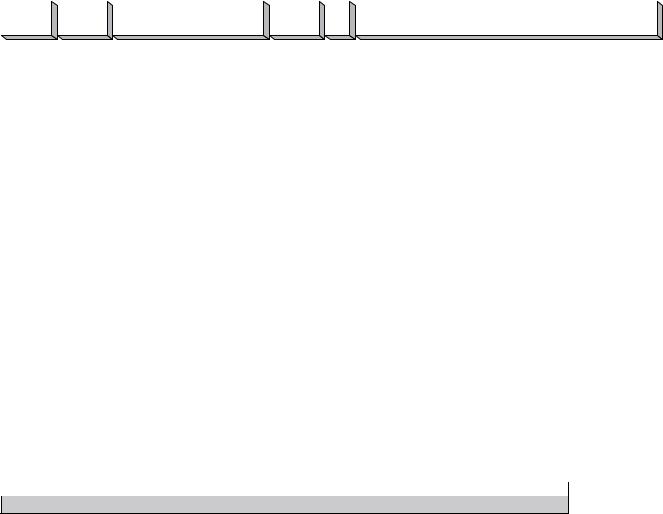
3-2. SDAP Protocol
This section describes the SDAP packet structure.
Header |
|
Community |
|
Product name |
|
|
Serial No. |
|
Power |
|
Location |
(4) |
|
(4) |
|
(12) |
|
|
(4) |
|
Status |
|
(24) |
|
|
|
|
|
(2) |
|
|||||
|
|
|
|
|
|
|
|
|
|
|
|
|
|
|
|
|
Fig.1 Packet structure |
|
|
||||
1)Header
The header consists of ID (16 bit), version (8 bit) and category (8 bits).
|
|
|
|
|
|
0 |
|
|
|
|
|
|
|
|
|
|
|
|
1 |
|
|
|
|
|
|
|
|
|
|
|
|
2 |
|
|
|
|
|
|
|
|
|
|
|
|
|
3 |
|
|
|
|
|
|
(Bit position) |
||||
0 |
|
1 |
|
2 |
3 |
|
4 |
5 |
|
6 |
|
7 |
|
8 |
|
9 |
|
0 |
1 |
|
2 |
3 |
|
4 |
|
5 |
|
6 |
|
7 |
|
8 |
9 |
|
0 |
1 |
|
2 |
|
3 |
|
4 |
|
5 |
|
|
6 |
7 |
|
8 |
|
9 |
|
0 |
|
1 |
|
|
|
|
|
|
|
|
|
|
|
|
|
|
|
|
|
|
|
|
|
|
|
|
|
|
|
||||||||||||||||||||||||||||||||
|
|
|
|
|
|
|
|
|
|
|
|
|
|
|
|
|
|
|
|
|
|
|
|
|
|
|
|
|
|
|
|
|
|
|
|
|
|
|
|
|
|
|
|
|
|
|
|
|
|
|
|
|
|
|
|
||
|
|
|
|
|
|
|
|
|
|
“DA” (16) |
|
|
|
|
|
|
|
|
|
|
|
|
|
|
|
|
|
Version (8) |
|
|
|
|
|
|
|
|
Category (8) |
|
|
|
|
|
|
||||||||||||||
Fig. 2 Header
ID
It is fixed to “DA”.
Version
This indicates the version number of protocol.
It is fixed to 01h (version 1).
Category
Category number 0x0a of the projector is entered here.
2)Community
The community that is set in the display equipment is entered. Community consists of four alphanumeric characters (case sensitive). The display equipment has the default value “SONY” when shipped
from the factory.
|
|
|
|
|
|
|
0 |
|
|
|
|
|
|
|
|
|
|
|
1 |
|
|
|
|
|
|
|
|
|
|
|
|
|
|
|
2 |
|
|
|
|
|
|
|
|
|
|
|
|
3 |
|
|
|
|
|
|
|
(Bit position) |
||||||||||
0 |
|
1 |
|
2 |
|
3 |
|
|
4 |
|
5 |
|
6 |
|
7 |
|
|
9 |
|
0 |
|
1 |
|
|
2 |
|
3 |
|
4 |
|
5 |
|
6 |
|
7 |
|
8 |
|
9 |
|
|
0 |
|
1 |
|
2 |
|
3 |
|
4 |
|
5 |
|
6 |
|
7 |
|
|
8 |
|
9 |
|
0 |
|
1 |
|
|
|
|
|
|
|
|
|
8 |
|
|
|
|
|
|
|
|
|
|
|
|
|
|
|
|
|
|
|
|
|
|
|
|
|
|
|
|||||||||||||||||||||||||||||||
Community (32)
Fig. 3 Community
3) Equipment Information
Product Name
Name of equipment (Maximum twelve characters)
In case, less than twelve characters, 00h is entered in the blank space.
Serial No.
Serial number is entered.
Power Status.
Power supply status of the equipment is entered.
Location
Information of installation location (Maximum twenty four characters)
In case, less than twenty four characters, 00h is entered in the blank space.
8 |
VPL-CX75/CX76/CX85/CX86/FX51/FX52/FX52L/PX35/PX40/PX41 |
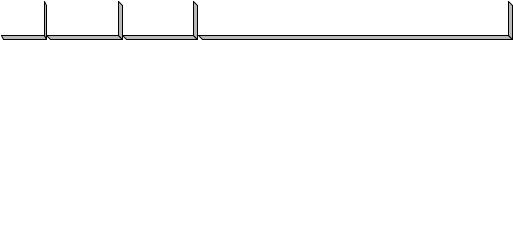
3-3. |
SDCP Protocol |
|
|||||
This section describes the packet structure of SDCP. |
|
||||||
|
|
|
|
|
|
|
|
Header |
|
Community |
|
Command |
|
|
Data (n) |
(2) |
|
(4) |
|
(4) |
|
|
|
|
|
|
|
|
|||
|
|
|
|
|
|
|
|
Fig. 1 Packet structure
3-3-1. Format
3-3-1-1. Header
The header consists of Version (8 bits) and Category (8 bits).
|
|
|
|
|
|
0 |
|
|
|
|
|
|
|
|
|
|
|
|
1 |
|
|
|
|
|
(Bit position) |
||
0 |
|
1 |
|
2 |
3 |
|
4 |
|
5 |
|
6 |
|
7 |
|
|
9 |
|
0 |
1 |
|
2 |
3 |
|
4 |
|
5 |
|
|
|
|
|
|
|
8 |
|
|
|
|
|
|
|||||||||||||||
|
|
|
|
|
|
|
|
|
|
|
|
|
|
|
|
|
|
|
|
|
|
|
|
|
|
||
|
|
|
|
Version (8) |
|
|
|
|
|
|
|
|
|
Category (8) |
|
|
|
|
|
||||||||
Fig. 2 Header structure
Version
This indicates the version number of protocol.
It is fixed to 02h (version 2).
Category
Category number 0x0a of the projector is entered here. Projector checks the category number. If a different category number is entered, the request is ignored.
3-3-1-2. Community
When the community Data matches the community that is set in the display equipment, the request is executed. Community consists of four alphanumeric characters (case sensitive). All display equipment has the default value “SONY” when shipped from the factory.
|
|
|
|
|
|
0 |
|
|
|
|
|
|
|
|
|
|
|
|
1 |
|
|
|
|
|
|
|
|
|
|
|
|
|
|
2 |
|
|
|
|
|
|
|
|
|
|
|
3 |
|
|
|
|
|
|
(Bit position) |
||||
0 |
|
1 |
|
2 |
3 |
|
4 |
5 |
|
6 |
|
7 |
|
8 |
|
9 |
|
0 |
1 |
|
2 |
3 |
|
|
4 |
|
5 |
|
6 |
|
7 |
|
|
8 |
9 |
|
0 |
1 |
|
2 |
|
3 |
|
4 |
|
5 |
|
6 |
7 |
|
8 |
9 |
|
0 |
|
1 |
|
|
|
|
|
|
|
|
|
|
|
|
|
|
|
|
|
|
|
|
|
|
|
|
|
|
|
||||||||||||||||||||||||||||||||
|
|
|
|
|
|
|
|
|
|
|
|
|
|
|
|
|
|
|
|
|
|
|
|
|
|
|
|
|
|
|
|
|
|
|
|
|
|
|
|
|
|
|
|
|
|
|
|
|
|
|
|
|
|
|
|
|
|
|
|
|
|
|
|
|
|
|
|
|
|
|
|
|
|
|
|
|
|
|
|
|
Community (32) |
|
|
|
|
|
|
|
|
|
|
|
|
|
|
|
|
|
|
|
|
|
|
|
|
||||||||||
n
Community should be entered with four characters. Three characters or less are not accepted.
VPL-CX75/CX76/CX85/CX86/FX51/FX52/FX52L/PX35/PX40/PX41 |
9 |
3-3-1-3. Command
This section describes the format of the request command and the response command.
|
|
|
|
|
|
0 |
|
|
|
|
|
|
|
|
|
|
|
|
1 |
|
|
|
|
|
|
|
|
|
|
|
|
2 |
|
|
|
|
|
|
|
|
|
|
|
|
|
3 |
|
|
|
|
|
(Bit position) |
||||
0 |
|
1 |
|
2 |
3 |
|
4 |
5 |
|
6 |
|
7 |
|
8 |
|
9 |
|
0 |
1 |
|
2 |
3 |
|
4 |
|
5 |
|
6 |
|
7 |
|
8 |
9 |
|
0 |
1 |
|
2 |
|
3 |
|
4 |
|
5 |
|
|
6 |
7 |
|
8 |
9 |
|
0 |
|
1 |
|
|
|
|
|
|
|
|
|
|
|
|
|
|
|
|
|
|
|
|
|
|
|
|
|
|
||||||||||||||||||||||||||||||||
|
|
|
|
|
|
|
|
|
|
|
|
|
|
|
|
|
|
|
|
|
|
|
|
|
|
|
|
|
|
|
|
|
|
|
|
|
|
|
|
|
|
|
|
|
|
|
|
|
|
|
|
|
|
|
||
|
|
Request/Response (8) |
|
|
|
|
|
|
|
|
|
|
|
|
|
Item No (16) |
|
|
|
|
|
|
|
|
|
|
|
|
|
|
Data Length (8) |
|
|
|
|
|
||||||||||||||||||||
(1) |
|
Request |
|
|
|
|
|
|
|
|
|
|
|
|
|
|
|
|
|
|
|
|
|
|
|
|
|
|
|
|
|
|
|
|
|
|
|
|
|
|
|
|
|
|
|
|
|
|
|
|
|
|
|
|||
This section describes the format of the request command that is issued from the host PC to the projector.
Community
This is the same alphanumeric characters as those of community that is set in the projector to which request is going to be sent.
Request
There are only two types of request. One is the GET request to acquire the projector information and status. The other is the SET request to modify the projector setup.
Request |
Contents |
|
|
SET (00h) |
Used to control turning the power on/off and to control the input selector, and to change the various setups. |
|
|
SET (01h) |
Used to acquire the installation information, equipment status and various setup values. |
|
|
Item No.
This is the item number of the request target.
Data Length
This is the length of the Data accompanying the request. The maximum length is 128 bytes. If there is no Data, it is 0.
Data
This is the Data accompanying the request.
(2) Response
This section describes the format of the response command which is used to return a response to the host PC from the projector.
Community
The same alphanumeric characters as those of the request is entered.
Response
The response returns the result of executing the request from the host PC.
Response |
Contents |
|
|
NG (00h) |
Indicates that the request is illegal or cannot be executed. |
|
|
OK (01h) |
Indicates that the request was executed correctly. |
|
|
Item No.
The same value as those of the request is entered.
Data Length
This is the length of the Data accompanying the response. The maximum length is 128 bytes. If there is no Data, it is 0.
Data
This is the Data accompanying the response.
10 |
VPL-CX75/CX76/CX85/CX86/FX51/FX52/FX52L/PX35/PX40/PX41 |
Loading...