


2-347-711-32(2)
Wireless
Microphone Package
Operating Instructions
Before operating the unit, please read this manual thoroughly and retain it for future reference.
UWP-C1/C2
UWP-S1/S2
UWP-X1/X2
2003 Sony Corporation
2

Table of Contents
Configuration of the |
|
Packages ............................. |
4 |
UWP-C1 ..................................... |
4 |
UWP-C2 ..................................... |
5 |
UWP-S1 ..................................... |
6 |
UWP-S2 ..................................... |
7 |
UWP-X1 .................................... |
8 |
UWP-X2 .................................... |
9 |
Features .................................. |
10 |
Precautions ............................. |
12 |
Parts Identification ................. |
13 |
Body-pack transmitter |
|
(UTX-B1) ................................. |
13 |
Hand-held microphone |
|
(UTX-H1) ................................ |
14 |
Portable diversity tuner |
|
(URX-P1) ................................. |
15 |
Half-rack size diversity tuner |
|
(URX-R1) ................................ |
17 |
Diversity tuner module |
|
(URX-M1) ............................... |
18 |
Power Supply ......................... |
20 |
Inserting the batteries ............... |
20 |
Attachment and Installation |
|
Procedures ........................ |
23 |
Attaching the supplied |
|
accessories to the body-pack |
|
transmitter (UTX-B1) .............. |
23 |
Attaching the supplied accessory |
|
to the hand-held microphone |
|
(UTX-H1) ................................ |
24 |
Attaching the supplied accessories |
|
to the portable diversity tuner |
|
(URX-P1) ................................. |
24 |
Installing the diversity tuner |
|
module (URX-M1) .................. |
25 |
Settings ................................... |
28 |
Setting the transmission |
|
channel ..................................... |
28 |
Setting the reception channel ... |
29 |
Detecting and selecting the |
|
available channels |
|
automatically (diversity tuner |
|
module (URX-M1) only) ......... |
30 |
Setting the attenuation level |
|
of the audio input ..................... |
31 |
Resetting the accumulated |
|
battery use time indication ....... |
32 |
Setting the RF output level ...... |
32 |
Setting the monitor level |
|
(portable diversity tuner |
|
(URX-P1) only) ....................... |
33 |
Operation ................................ |
34 |
System Configurations .......... |
35 |
Error Messages ...................... |
38 |
Troubleshooting ..................... |
39 |
Specifications ......................... |
41 |
Appendix ................................. |
45 |
Wireless microphone system |
|
frequency list ............................ |
45 |
AC adapter for use with the |
|
URX-R1 ................................... |
47 |
3
ConfigurationConfigurationof the Packagesof the Packages
This operation manual is for the UWP-C1/C2/S1/S2/X1/X2 wireless microphone packages. The contents of each package are described below.
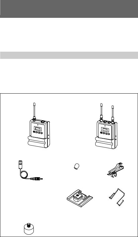
UWP-C1
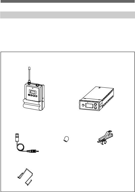
The UWP-C1 consists of a body-pack transmitter (UTX-B1) and a portable diversity tuner (URX-P1). When used in conjunction with a compact camcorder, the UWP-C1 makes a mobile system for ENG (Electronic News Gathering) or EFP (Electronic Field Production) purposes.
Body-pack transmitter |
Portable diversity tuner |
(UTX-B1) (1) |
(URX-P1) (1) |
Supplied accessories
• Omni-directional lavalier microphone • Wind screen (1) |
• Holder clip (1) |
(1) |
|
• XLR-BMP conversion cable (for use • Shoe mount adapter (1) • Belt clip (2) with the URX-P1 only) (1)
• Stereo mini plug-BMP conversion cable (for use with the URX-P1 only)
(1)
• Microphone stand adapter (1) |
• Operation manual (1) |
4
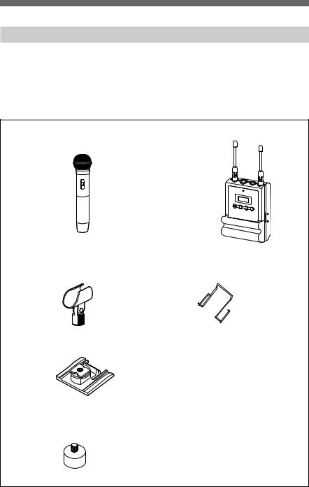
UWP-C2
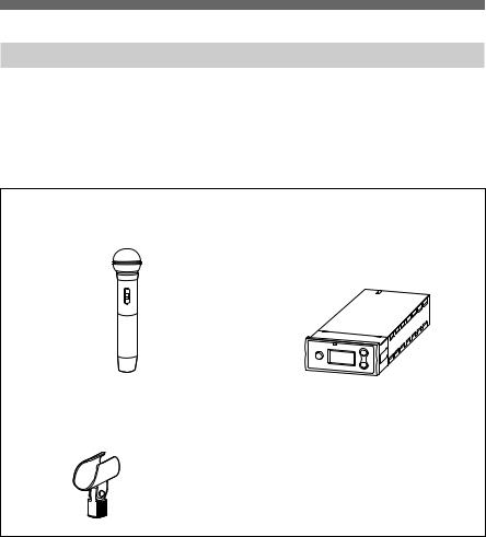
The UWP-C2 consists of a hand-held microphone (UTX-H1) and a portable diversity tuner (URX-P1). When used in conjunction with a compact camcorder, the UWP-C2 makes a mobile system for ENG (Electronic News Gathering) or EFP (Electronic Field Production) purposes.
Hand-held microphone |
Portable diversity tuner |
(UTX-H1) (1) |
(URX-P1) (1) |
Supplied accessories
• Microphone holder (1)
• Shoe mount adapter (1)
• Belt clip (1)
•XLR-BMP conversion cable (for use with the URX-P1 only) (1)
•Stereo mini plug-BMP conversion cable (for use with the URX-P1 only) (1)
• Microphone stand adapter (1) |
• Operation manual (1) |
5
Configuration of the Packages
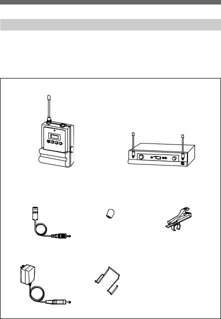
UWP-S1
The UWP-S1 consists of a body-pack transmitter (UTX-B1) and a half-rack size diversity tuner (URX-R1). The UWP-S1 is suitable for constructing a wireless system for AV presentations.
Body-pack transmitter |
Half-rack size diversity tuner |
(UTX-B1) (1) |
(URX-R1) (1) |
Supplied accessories
• Unidirectional lavalier |
• Wind screen (1) |
• Holder clip (1) |
microphone (1) |
|
|
• AC adapter (1) (See |
• Belt clip (1) |
• Operation manual (1) |
|||
page 47.) |
|
|
|||
|
|
|
|
|
|
6
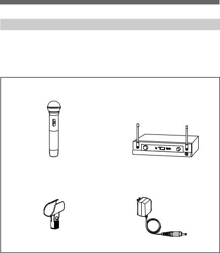
UWP-S2
The UWP-S2 consists of a hand-held microphone (UTX-H1) and a half-rack size diversity tuner (URX-R1). The UWP-S2 is suitable for constructing a wireless system for AV presentations.
Hand-held microphone |
Half-rack size diversity tuner |
||
(UTX-H1) (1) |
(URX-R1) (1) |
||
|
|
|
|
Supplied accessories
• Microphone holder (1) |
• AC adapter (1) (See page 47.) |
• Operation manual (1)
7
Configuration of the Packages
UWP-X1
The UWP-X1 consists of a body-pack transmitter (UTX-B1) and a diversity tuner module (URX-M1). By installing the tuner module into a tuner base unit or a powered mixer, the system construction to meet the desired purpose of use and required system scale becomes possible.
Body-pack transmitter |
Diversity tuner module |
(UTX-B1) (1) |
(URX-M1) (1) |
Supplied accessories
• Unidirectional lavalier |
• Wind screen (1) |
• Holder clip (1) |
microphone (1) |
|
|
• Belt clip (1) |
• Operation manual (1) |
8
UWP-X2
The UWP-X2 consists of a hand-held microphone (UTX-H1) and a diversity tuner module (URX-M1) . By installing the tuner module into a tuner base unit or a powered mixer, the system construction to meet the desired purpose of use and required system scale becomes possible.
Hand-held microphone |
Diversity tuner module |
||
(UTX-H1) (1) |
(URX-M1) (1) |
||
|
|
|
|
|
|
|
|
Supplied accessories
• Microphone holder (1) |
• Operation manual (1) |
9

FeaturesFeatures
Each of the UWP-C1/C2/S1/S2/X1/ X2 wireless microphone packages (referred to as the UWP series hereafter) combines a transmitter (body-pack transmitter (UTX-B1) or hand-held microphone (UTX-H1)) and a receiver (portable diversity tuner (URX-P1), half-rack size diversity tuner (URX-R1), or diversity tuner module (URX-M1)). The UWP series can be used with a compact camcorder for ENG (Electronic News Gathering) purposes, and with a powered mixer for AV presentations or as a PA (public address) system.
Note
The UWP series is not compatible with conventional WRT series transmitters, WRR series tuners, or WRU series tuner units.
The features of each package are described below.
UWP-C1
Body-pack transmitter (UTX-B1)
This is a small and lightweight transmitter with a crystal-controlled PLL (phase lock loop) synthesized system and a BMP-type microphone input connector. The RF power output can be set at 10 mW or at 2 mW.
Portable diversity tuner (URX-P1)
This tuner employs a space diversity system with little signal dropout and two angle-adjustable antennas. It comes with an adapter for mounting the tuner on the compact camcorder (DSR-PDX10/PDX10P/PD150/ PD150P, etc.).
UWP-C2
Hand-held microphone (UTX-H1)
This microphone is equipped with a built-in antenna and a unidirectional dynamic microphone unit. The RF power output can be set at 10 mW or at 2 mW.
Portable diversity tuner (URX-P1)
This tuner employs a space diversity system with little signal dropout and two angle-adjustable antennas. It comes with an adapter for mounting the tuner on the compact camcorder (DSR-PDX10/PDX10P/PD150/ PD150P, etc.).
UWP-S1
Body-pack transmitter (UTX-B1)
This is a small and lightweight transmitter with a crystal-controlled PLL (phase lock loop) synthesized system and a BMP-type microphone input connector. The RF power output can be set at 10 mW or at 2 mW.
10
Half-rack size diversity tuner (URX-R1)
This tuner employs a space diversity system with little signal dropout and two angle-adjustable antennas. It comes with two types of audio connectors (1/4-inch jack and XLR type) on the rear panel.
UWP-S2
Hand-held microphone (UTX-H1)
This microphone is equipped with a built-in antenna and a unidirectional dynamic microphone unit. The RF power output can be set at 10 mW or at 2 mW.
Half-rack size diversity tuner (URX-R1)
This tuner employs a space diversity system with little signal dropout and two angle-adjustable antennas. It comes with two types of audio connectors (1/4-inch jack and XLR type) on the rear panel.
UWP-X1
Body-pack transmitter (UTX-B1)
This is a small and lightweight transmitter with a crystal-controlled PLL (phase lock loop) synthesized system and a BMP-type microphone input connector. The RF power output can be set at 10 mW or at 2 mW.
Diversity tuner module (URX-M1)
This tuner module can be incorporated into the MB-806A Tuner Base Unit or SRP-X700P Powered Mixer.
UWP-X2
Hand-held microphone (UTX-H1)
This microphone is equipped with a built-in antenna and a unidirectional dynamic microphone unit. The RF power output can be set at 10 mW or at 2 mW.
Diversity tuner module (URX-M1)
This tuner module can be incorporated into the MB-806A Tuner Base Unit or SRP-X700P Powered Mixer.
11

PrecautionsPrecautions
•The UWP series product must be used within a temperature range of 0°C to 40°C (32°F to 104°F).
•Operating the UWP series product near electrical equipment (motors, transformers, or dimmers) may cause it to be affected by electromagnetic induction. Keep the UWP series product as far from such equipment as possible.
•The presence of the lighting equipment may produce electrical interference over the entire frequency range. Position the UWP series product so that interference is minimized.
•To avoid degradation of the signal- to-noise ratio, do not use the UWP series product in noisy places or in locations subject to vibration, such as the following:
—near electrical equipment, such as motors, transformers or dimmers
—near air conditioning equipment or places subject to direct air flow from an air conditioner
—near public address loudspeakers
—where adjacent equipment might knock against the tuner
Keep the UWP series product as far from such equipment as possible or use buffering material.
•Clean the surface and the connectors of the UWP series product with a dry, soft cloth. Never use thinner, benzene, alcohol or any other chemicals, since these may mar the finish.
To prevent electromagnetic interference from portable communication devices
The use of portable telephones and other communication devices near the UWP series product may result in malfunction and interference with audio signals. It is recommended that portable communication devices near the UWP series product be turned off.
12

Parts Identification
Body-pack transmitter
(UTX-B1)
1 Antenna |
2 Audio input connector
Connect the supplied lavalier microphone here.
3 Power indicator
Lights up red when the transmitter is tuned on.
4 Display section
AB C D
AF RF BATT
H
L
CH
E
A AF (audio frequency) indication
Appears whenever the input audio signal is stronger than the reference level.
B RF (antenna output) indication
Appears during signal transmission from the antenna.
C RF (antenna output) level indication
Shows the RF output level setting.
For details, see “Setting the RF output level” on page 32.
D BATT (battery) indication
Shows the battery condition.
For details, see “Power Supply” on page 20.
E CH (channel) indication
Shows the transmission channel. Each time you press the SET button in transmission mode, the channel indication changes as follows.
For details, see “Settings” on page 28.
Transmission 


 channel


Transmission |
Press |
|
the |
||
frequency |
||
SET |
||
|
||
Attenuation |
button. |
|
|
||
level of the |
|
|
input signal |
|
|
Accumulated |
|
|
battery use |
|
|
time |
|
13
Parts Identification
5 + (+ selection) / – (– selection/ reset) buttons
Press these buttons to set the transmission channel, frequency, or attenuation level of the input signal. The “–” button resets the accumulated battery use time to “00:00”.
6 Battery compartment
Accommodates two LR6 (size AA) alkaline batteries.
For details on how to insert the batteries, see “Power Supply” on page 20.
7 SET button
Press to change and enter display parameters.
For details, see “Settings” on page 28.
8 POWER switch
Turns the power of the transmitter ON or OFF.
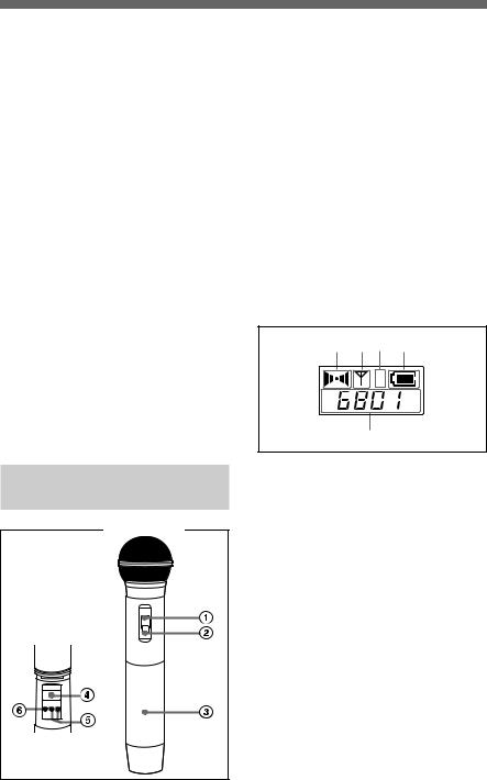
Hand-held microphone
(UTX-H1) |
The rear |
side of the |
battery |
compartment |
14 |
1 Power indicator
Lights up red when the microphone is turned on.
2 POWER switch
Turns the power of the microphone ON or OFF.
3 Battery compartment
Accommodates two LR6 (size AA) alkaline batteries.
For details on how to insert the batteries, see “Power Supply” on page 20.
4 Display section
AB C D
H
L
E
A AF (audio frequency) indication
Appears whenever the input audio signal is stronger than the reference level.
B RF (antenna output) indication
Appears during signal transmission from the antenna.
C RF (antenna output) level indication
Shows the RF output level setting.
For details, see “Setting the RF output level” on page 32.

D BATT (battery) indication
Shows the battery condition.
For details, see “Power Supply” on page 20.
E CH (channel) indication
Shows the transmission channel. Each time you press the SET button, the channel indication changes as follows.
For details, see “Settings” on page 28.
Transmission channel
Transmission |
Press |
frequency |
the |
|
SET |
Attenuation |
button. |
|
|
level of the |
|
input signal |
|
Accumulated |
|
battery use |
|
time |
|
5 + (+ selection) / – (– selection/ reset) buttons
Press these buttons to set the transmission channel, frequency, or attenuation level of the input signal. The “–” button resets the accumulated battery use time to “00:00”.
6 SET button
Press to change display parameters.
For details, see “Settings” on page 28.
Portable diversity tuner
(URX-P1)
1 Antennas a/b
The angle of the antennas can be adjusted manually.
2 MONITOR connector (3.5-mm diameter stereo mini jack)
To monitor the tuner output, connect the headphones to this connector.
3 RF (radio frequency) indicator
Indicates the strength of the RF input signal.
On in green: RF input is 15 dBµ* or more.
Off: RF input is less than 15 dBµ*.
......................................................................................................................................................................
* 0 dBµ = 1 µVEMF
15
 Loading...