


3-861-069-11(1)
Integrated AV
Amplifier
Operating Instructions |
EN |
Mode d’emploi |
F |
Gebruiksaanwijzing |
NL |
Bruksanvisning |
S |
TA-VE610
ã 1997 by Sony Corporation

WARNING
To prevent fire or shock hazard, do not expose the unit to rain or moisture.
To avoid electrical shock, do not open the cabinet. Refer servicing to qualified personnel only.
Do not install the appliance in a confined space, such as a bookcase or built-in cabinet.
Precautions
On safety
•Should any solid object or liquid fall into the cabinet, unplug the amplifier and have it checked by qualified personnel before operating it any further.
On power sources
•Before operating the amplifier, check that the operating voltage is identical with your local power supply. The operating voltage is indicated on the nameplate at the rear of the amplifier.
•The amplifier is not disconnected from the AC power source as long as it is connected to the wall outlet, even if the amplifier itself has been turned off.
•If you are not going to use the amplifier for a long time, be sure to disconnect the amplifier from the wall outlet. To disconnect the AC power cord, grasp the plug itself; never pull the cord.
•One blade of the plug is wider than the other for the purpose of safety and will fit into the wall outlet only one way. If you are unable to insert the plug fully into the outlet, contact your dealer.
•AC power cord must be changed only at the qualified service shop.
On placement
•Place the amplifier in a location with adequate ventilation to prevent heat buildup and prolong the life of the amplifier.
•Do not place the amplifier near heat sources, or in a place subject to direct sunlight, excessive dust or mechanical shock.
•Do not place anything on top of the cabinet that might block the ventilation holes and cause malfunctions.
On operation
•Before connecting other components, be sure to turn off and unplug the amplifier.
On cleaning
•Clean the cabinet, panel and controls with a soft cloth slightly moistened with a mild detergent solution. Do not use any type of abrasive pad, scouring powder or solvent such as alcohol or benzine.
If you have any question or problem concerning your amplifier, please consult your nearest Sony dealer.
2EN

About This Manual
The instructions in this manual are for model TA-VE610.
Conventions
•The instructions in this manual describe the controls on the amplifier. You can also use the controls on the remote if they have the same or similar names as those on the amplifier.
•A “Quick Reference Guide” is supplied on page 29.
•The “Remote Button Descriptions” section on page 26 provides an overview of the remote buttons.
•The following icons are used in this
manual:
ZIndicates that you can use only the remote to do the task.
zIndicates hints and tips for making the task easier.
This amplifier incorporates the Dolby* Pro Logic Surround system.
*Manufactured under license from Dolby Laboratories Licensing Corporation. DOLBY, the double-D symbol aand “PRO LOGIC” are trademarks of Dolby Laboratories Licensing Corporation.
TABLE OF CONTENTS
Getting Started
Unpacking 4
Hookup Overview 4
Audio Component Hookups 5
Speaker System Hookups 5
TV/VCR Hookups 7
AC Hookups 8
Before You Use Your Amplifier 9
Basic Operations
Selecting a Component 9
Indexing Program Sources 12
Recording 13
Using the Sleep Timer 14
Dolby Surround Setup
Dolby Pro Logic 14 EN
Sound Adjustment
Using Pre-programmed Sound Fields 16
Customizing the Sound Fields 17
Advanced Remote Operations
Operating One Component While Using Another (background operation)
19
Changing the Factory Setting of a FUNCTION Button 20
Additional Information
Troubleshooting 21
Specifications 22
Glossary 23
Table of Functions of the SET UP Button 24
Rear Panel Descriptions 25
Remote Button Descriptions 26
Index 28
Quick Reference Guide 29
3EN
Getting Started
Unpacking
Check that you received the following items with the amplifier:
•Remote commander (remote) RM-U501 (1)
•Size AA (R6) batteries (2)
Inserting batteries into the remote
Insert two size AA (R6) batteries with the + and – on the battery compartment. When using the remote, point it at the remote sensor gon the amplifier.
 ] } ]
] } ]

 }
}

zWhen to replace batteries
Under normal use, the batteries should last for about 6 months. When the remote no longer operates the amplifier, replace both batteries with new ones.
Notes
•Do not leave the remote in an extremely hot or humid place.
•Do not use a new battery with an old one.
•Do not expose the remote sensor to direct sunlight or lighting apparatuses. Doing so may cause a malfunction.
•If you don’t use the remote for an extended period of time, remove the batteries to avoid possible damage from battery leakage and corrosion.
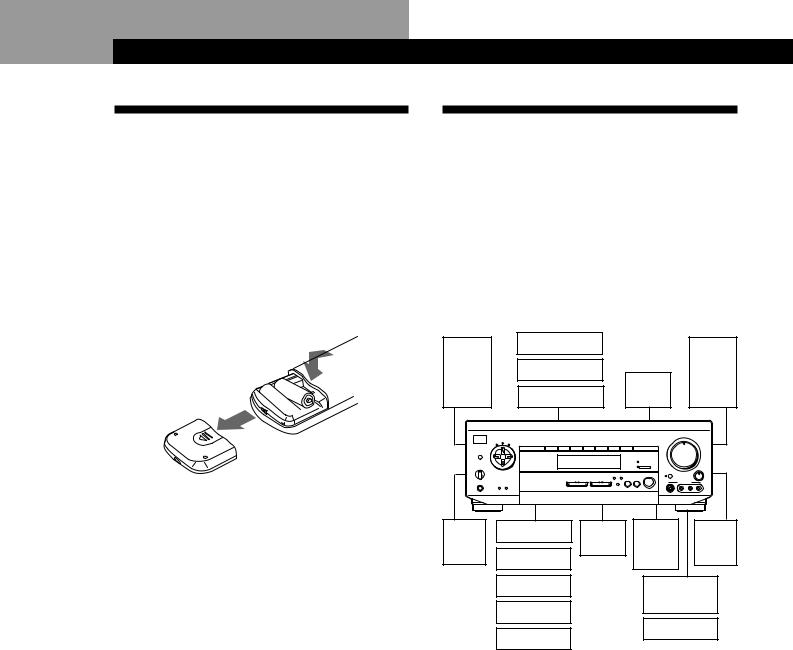
Hookup Overview
The amplifier allows you to connect and control the following audio/video components. Follow the hookup procedures for the components that you want to connect to the amplifier on the pages specified. To learn the locations and names of each jacks, see “Rear Panel Descriptions” on page 25.
Speaker |
|
|
|
|
|
|
|
|
|
|
System |
|
|
|
|
|
|
|
|
|
|
Hookups |
TV/VCR Hookups (7) |
|
|
|
|
|
|
|
|
|
(5) |
|
|
|
|
|
|
|
|
||
TV |
|
|
|
|
|
|
|
|
|
|
|
|
|
|
|
|
|
|
|
|
|
Front |
VCR |
|
|
|
|
|
|
|
|
Front |
speaker |
|
|
|
|
|
|
|
speaker |
||
|
|
Active |
|
|
|
|
||||
(L) |
|
|
|
|
|
|
|
(R) |
||
LD player |
|
woofer |
|
|
|
|
|
|||
|
|
|
|
|
|
|
|
|||
|
|
|
|
|
MASTER VOLUME |
|
|
|||
|
|
|
|
4 |
• |
• • 5 |
• • |
• |
|
|
|
|
|
|
|
|
6 |
|
|||
|
|
|
|
• |
|
|
|
|
• • |
|
|
VIDEO 1 VIDEO 2 VIDEO 3 TV/LD |
TAPE/MD CD TUNER |
PHONO |
• |
|
|
|
|
|
• |
|
3 |
|
|
|
|
|
7 |
|||
|
|
|
|
• |
|
|
|
|
|
• |
|
|
|
|
• |
|
|
|
|
|
• |
|
|
|
|
• |
|
|
|
|
|
• |
|
|
|
|
2 |
|
|
|
|
|
8 |
|
|
|
|
• |
|
|
|
|
|
• |
|
|
|
|
• |
|
|
|
|
|
• |
|
|
|
DIRECT PASS |
• |
|
|
|
|
|
• |
|
|
|
|
1 |
|
|
|
|
|
9 |
SPEAKERS |
|
|
5.1 INPUT |
• |
|
|
|
|
|
• |
g |
|
• |
|
|
|
|
|
|
||
|
|
|
• |
|
|
|
|
• |
• BALANCE |
|
+ |
|
|
|
BASS 0 |
|
|
|
|
10 |
|
|
|
SOUND FIELD |
BOOST |
|
|
|
|
|
|
|
|
|
|
ON / OFF |
|
|
|
|
|
|
|
|
VIDEO FUNCTION |
AUDIO FUNCTION |
GENRE MODE |
|
|
VIDEO 3 INPUT |
|
L |
R |
|
PHONES |
|
|
|
|
|
|
|
|
||
Rear |
CD player |
Center |
Wireless |
|
|
|
|
|
Rear |
|
speaker |
speaker |
rear |
|
|
|
|
|
|
speaker |
|
(L) |
Tuner |
|
speaker |
|
|
|
|
|
(R) |
|
|
Tape deck |
|
Video camera |
|||||||
|
MD deck |
|
|
recorder |
||||||
|
|
|
|
|
|
|
|
|
|
|
|
Turntable |
|
Video game |
|||||||
|
|
|
|
|
|
|
|
|
|
|
|
Audio Component |
|
|
|
|
|
|
|
|
|
|
Hookups (5) |
|
|
|
|
|
|
|
|
|
Before you get started
•Turn off the power to all components before making any connections.
•Do not connect the AC power cords until all of the connections are completed.
•Be sure to make connections firmly to avoid hum and noise.
•When connecting an audio/video cable, be sure to match the color-coded pins to the appropriate jacks on the components: Yellow (video) to Yellow; White
(left, audio) to White; and Red (right, audio) to Red.
4EN

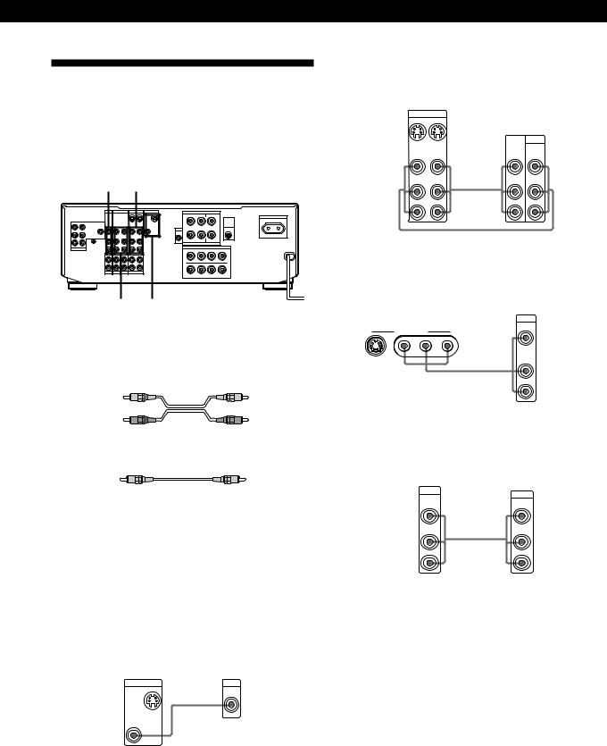
Audio Component Hookups
Overview
This section describes how to connect your audio components to the amplifier.
PHONO |
CD |
|
|
||||
|
|
TV / LD |
VIDEO 2 |
VIDEO 1 |
MONITOR |
||
|
|
|
|
|
OUT |
IN |
OUT |
FRONT |
REAR |
|
|
|
|
|
|
|
VIDEO |
VIDEO |
VIDEO |
VIDEO |
VIDEO |
VIDEO |
VIDEO |
L |
IN |
IN |
OUT |
IN |
OUT |
IN |
OUT |
R
|
AUDIO |
AUDIO |
AUDIO |
AUDIO |
AUDIO |
|
IN |
OUT |
IN |
OUT |
IN |
|
SIGNAL |
|
|
|
L |
|
GND |
|
|
|
|
CENTER WOOFER |
y |
|
|
|
|
5.1 INPUT |
|
|
|
|
R |
|
IN |
IN |
IN |
RECOUT |
IN |
|
|
|
|
|
L |
|
|
|
|
|
R |
|
PHONO |
TUNER |
CD |
TAPE / MD |
|
SURROUND SPEAKERS
R |
REAR L |
CENTER |
|
AC OUTLET |
|
|
|
|
|
|
|
|
|
|
|
WIRELESS |
SWITCHED 100W MAX |
+ |
|
|
+ |
REAR |
|
|
|
|
|
SPEAKER |
|
WOOFER |
|
|
|
|
|
AUDIO – |
|
|
– |
|
|
OUT |
|
|
|
|
|
R |
L |
|
|
|
|
|
IMPEDANCE USE 4–16 Ω |
|
|
|
|
|
FRONT SPEAKERS |
|
|
||
+ |
IMPEDANCE USE 4–16 |
Ω |
+ |
|
|
|
– – |
|
|||
A |
|
|
|
A |
|
R + |
|
– – |
|
+ L |
|
B |
|
|
|
B |
|
TUNER TAPE/MD
What cords will I need?
Audio cords (not supplied) (1 for each CD player, tuner, and turntable; 2 for each tape deck or MD deck)
White (L) |
White (L) |
Red (R) |
Red (R) |
Hookups
The arrow çindicates signal flow.
CD player
Amplifier |
CD player |
IN |
OUTPUT |
L |
LINE |
|
Ç  L
L
R
R
CD
Tuner
Amplifier Tuner
IN |
OUTPUT |
L |
LINE |
Ç  L
L
R
R
TUNER
Tape deck or MD deck
Amplifier |
Tape deck or MD deck |
|
RECOUT IN |
OUTPUT |
INPUT |
L |
LINE |
LINE |
|
|
|
Ç 
 L
L
R
R
TAPE/MD
ç
Getting Started
Turntable
Amplifier Turntable
IN |
OUTPUT |
L |
LINE |
Ç  L
L
R
R
PHONO
If your turntable has an earth lead
To prevent hum, connect the earth lead to the ySIGNAL GND terminal on the amplifier.
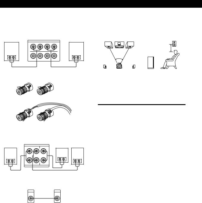
Speaker System Hookups
Overview
This section describes how to connect your speakers to the amplifier. Although front (left and right) speakers are required, center and rear speakers are optional.
Adding center and rear speakers will enhance the surround effects. Connecting an active woofer will increase bass response.
|
|
|
|
SURROUND |
|
|
|
SURROUND |
|||
WOOFER |
SPEAKERS REAR |
|
SPEAKERS CENTER |
||||||||
|
TV / LD |
VIDEO 2 |
VIDEO 1 |
MONITOR |
|
SURROUND SPEAKERS |
|
|
|
||
|
|
|
|
OUT IN |
OUT |
|
R |
REAR L CENTER |
|
AC OUTLET |
|
|
|
|
|
|
|
|
|
|
|
WIRELESS |
SWITCHED 100W MAX |
FRONT REAR |
VIDEO VIDEO |
VIDEO VIDEO VIDEO VIDEO |
VIDEO |
+ |
|
|
|
+ REAR |
|
||
L |
|
|
|
|
SPEAKER |
|
|||||
IN IN |
OUT |
IN |
OUT IN |
OUT |
|
|
|
|
|
|
|
|
|
|
|
|
|
WOOFER |
|
|
|
|
|
|
|
|
|
|
|
AUDIO – |
|
|
|
– |
|
R |
AUDIO |
AUDIO AUDIO AUDIO AUDIO |
|
OUT |
|
|
|
|
|
||
|
IN |
OUT |
IN |
OUT IN |
|
|
|
|
|
|
|
|
SIGNAL |
|
|
|
L |
|
R |
L |
|
|
|
|
GND |
|
|
|
|
|
IMPEDANCE USE 4–16 Ω |
|
|
|
|
CENTER WOOFER |
y |
|
|
|
|
|
|
|
|
|
|
|
|
|
|
+ |
|
FRONT SPEAKERS |
|
||||
5.1 INPUT |
|
|
|
|
R |
|
– – |
Ω |
+ |
|
|
|
|
|
|
|
|
|
IMPEDANCE USE 4–16 |
|
|
|
|
|
IN |
IN |
IN |
RECOUT IN |
|
A |
|
|
|
A |
|
|
|
|
|
|
L |
|
|
|
|
|
|
|
|
|
|
|
|
R + |
|
– – |
|
+ L |
|
|
|
|
|
|
R |
|
|
|
|
|
|
|
|
|
|
|
|
B |
|
|
|
B |
|
|
PHONO TUNER CD |
TAPE / MD |
|
|
|
|
|
|
|
||
|
FRONT SPEAKERS A |
|
WIRELESS |
|
|||||||
|
|
|
|
|
|
|
|
|
|
REAR SPEAKER |
|
What cords will I need?
• Speaker cord (not supplied) (1 for each speaker)
(+) |
(+) |
(–)
 (–)
(–)
Twist the stripped ends of the cord about 2/3 inch (15 mm). Be sure to match the speaker cord to the appropriate terminal on the components: + to + and – to –. If the cords are reversed, the sound will be distorted and will lack bass.
•Monaural audio cord (not supplied) (1 for an active woofer)
Black |
Black |
5EN
Getting Started
Hookups |
|
|
|
|
Speaker placement |
|
Front speakers |
|
|
|
|
For optimum surround sound effect, place your |
|
Front speaker |
|
|
|
Front speaker |
speakers as shown below. |
|
|
Amplifier |
|
|
Rear speaker |
||
(R) |
|
|
(L) |
|
||
|
FRONT SPEAKERS |
|
|
|||
|
+ |
IMPEDANCE USE 4–16 Ω |
+ |
|
|
|
|
– – |
|
|
60 - 90 cm |
||
|
A |
|
A |
|
|
|
}] |
R + |
– – |
+ L |
}] |
45° |
Front speaker |
|
B |
|
B |
|
||
To connect the speaker cords
|
] |
|
} |
|
|
|
|
|
|
|
] |
|
} |
|
Rear and center speakers |
|
|
||
Rear speaker |
Amplifier |
Rear speaker |
||
(R) |
SURROUND SPEAKERS |
Center speaker |
(L) |
|
|
R |
REAR L CENTER |
|
|
|
+ |
|
+ |
|
}] |
|
|
}] |
}] |
– |
|
– |
||
|
R |
L |
|
|
|
|
IMPEDANCE USE 4–16 Ω |
|
|
Active woofer |
|
|
|
|
|
Amplifier |
Active woofer |
|
|
|
WOOFER |
INPUT |
|
|
AUDIO
OUT ç
Wireless rear speaker
When using an optional Sony wireless rear speaker system, connect the transmitter to the WIRELESS REAR SPEAKER jack.
Note
Do not connect any other component to the WIRELESS REAR SPEAKER jack.
zIf you have an additional front speaker system
Connect them to the FRONT SPEAKERS B terminals.
Note
If you use front speakers with low maximum power input, adjust the volume carefully to avoid excessive output on the speakers.
Selecting the speaker system
If you connect only one set of front speakers, set the SPEAKERS selector on the front panel to A. If you connect two sets of front speakers, see the following:
To drive |
Set SPEAKERS selector to |
|
|
Speaker system A (connected |
A |
to the FRONT SPEAKERS A |
|
terminals) |
|
|
|
Speaker system B (connected |
B |
to the FRONT SPEAKERS B |
|
terminals) |
|
|
|
Both speaker systems A and B |
A+B |
(parallel connection) |
|
|
|
6EN
Getting Started
TV/VCR Hookups
Overview
This section describes how to connect video components to the amplifier.
TV/LD VIDEO 1
|
|
|
TV / LD |
VIDEO 2 |
VIDEO 1 |
MONITOR |
|
SURROUND SPEAKERS |
|
|
|
||||
|
|
|
|
|
|
OUT |
IN |
OUT |
|
R |
REAR L |
CENTER |
|
AC OUTLET |
|
|
|
|
|
|
|
|
|
|
|
|
|
|
|
|
|
|
|
|
|
|
|
|
|
|
|
|
|
|
|
WIRELESS |
SWITCHED 100W MAX |
FRONT |
REAR |
VIDEO |
VIDEO |
VIDEO |
VIDEO |
VIDEO |
VIDEO |
VIDEO |
+ |
|
|
|
+ |
REAR |
|
L |
|
|
|
|
|
|
SPEAKER |
|
|||||||
|
IN |
IN |
OUT |
IN |
OUT |
IN |
OUT |
|
|
|
|
|
|
|
|
|
|
|
|
|
|
|
|
|
WOOFER |
|
|
|
|
|
|
|
|
|
|
|
|
|
|
|
AUDIO – |
|
|
|
– |
|
|
R |
|
|
AUDIO |
AUDIO |
AUDIO |
AUDIO |
AUDIO |
|
OUT |
|
|
|
|
|
|
|
|
|
|
|
|
|
|
|
|
|
|||||
|
|
|
IN |
OUT |
IN |
OUT |
IN |
|
|
|
|
|
|
|
|
|
|
SIGNAL |
|
|
|
|
|
L |
|
R |
L |
|
|
|
|
|
|
GND |
|
|
|
|
|
|
|
IMPEDANCE USE 4–16 Ω |
|
|
|
||
CENTER |
WOOFER |
y |
|
|
|
|
|
|
|
|
|
|
|
||
|
|
|
|
|
|
+ |
|
FRONT SPEAKERS |
+ |
|
|||||
5.1 INPUT |
|
|
|
|
|
|
R |
|
|
– – |
Ω |
|
|||
|
|
|
|
|
|
|
|
|
|
IMPEDANCE USE 4–16 |
|
|
|
||
|
|
|
IN |
IN |
IN |
RECOUT |
IN |
|
A |
|
|
|
|
A |
|
|
|
|
|
|
|
|
|
L |
|
|
|
|
|
|
|
|
|
|
|
|
|
|
|
|
R + |
|
|
– – |
|
+ L |
|
|
|
|
|
|
|
|
|
R |
|
|
|
|
|
|
|
|
|
|
|
|
|
|
|
|
B |
|
|
|
|
B |
|
|
|
|
PHONO |
TUNER |
CD |
TAPE / MD |
|
|
|
|
|
|
|
|
|
VIDEO 2 MONITOR
What cables will I need?
•Audio/video cable (not supplied) (1 for each TV or LD player; 2 for each VCR)
Yellow |
Yellow |
White (L) 
 White (L)
Red (R) |
Red (R) |
• Video cable (not supplied) (1 for a TV monitor)
Yellow |
Yellow |
zIf you want to watch higher quality video images
You can connect an S-VIDEO cable (not supplied) to the VIDEO 1, VIDEO 3, or MONITOR jack.
Hookups
The arrow çindicates signal flow.
TV monitor
If you use a TV monitor, do not connect anything to the TV/ LD VIDEO IN jack.
Amplifier |
TV monitor |
MONITOR |
INPUT |
OUT |
VIDEO |
|
ç |
VIDEO |
|
OUT |
|
VCR (via the VIDEO 1/2 jacks)
If you have two VCRs, connect the second one to the VIDEO 2 jacks.
Amplifier
VIDEO 1
OUT |
IN |
VCR |
|
|
|
||
|
|
OUTPUT |
INPUT |
VIDEO |
VIDEO |
|
|
OUT |
IN |
VIDEO |
VIDEO |
|
|
||
AUDIO |
AUDIO |
Ç AUDIO |
AUDIO |
OUT |
IN |
||
|
|
L |
L |
|
|
R |
R |
ç
Video camera recorder or video game
Use the VIDEO 3 INPUT jacks on the front panel.
|
Video camera recorder or |
|
|
|
video game |
Amplifier |
|
OUTPUT |
|
VIDEO |
|
|
|
|
VIDEO 3 INPUT |
|
|
S VIDEO VIDEO L AUDIO R |
Ç |
AUDIO |
|
|
L |
R
TV or LD player
If you have an additional TV or LD player, connect it to the VIDEO 2 jacks.
Amplifier |
|
TV or LD player |
TV/LD |
|
OUTPUT |
VIDEO |
|
|
IN |
|
VIDEO |
|
|
|
AUDIO |
Ç |
AUDIO |
IN |
||
L |
|
L |
R |
|
R |
(Continued)
7EN
Getting Started
zYou can play decoded Dolby Digital (AC-3) soundtracks through the speakers connected to the amplifier
If you have a Dolby Digital (AC-3) decoder, you can use the amplifier to amplify a decoded Dolby Digital (AC-3) soundtrack with the following connections. Refer to the instruction manual supplied with your Dolby Digital (AC-3) decoder.
Amplifier
|
FRONT |
REAR |
|
|
|
L |
|
VIDEO |
|
|
|
IN |
|
|
|
R |
|
|
|
|
CENTER |
WOOFER |
|
|
|
5.1 INPUT |
|
|
|
Dolby Digital |
Ç |
Ç Ç |
Ç |
Ç |
(AC-3) decoder |
||||
etc. |
|
|
|
|
|
PRE OUT |
DIGITAL |
|
|
|
|
REAR FRONT |
|
|
|
|
|
|
|
CENTER |
|
|
|
|
|
|
|
IN |
|
WOOFER |
|
|
|
|
DVD player |
|
|
Ç |
|
|
|
|
|
|
|
DIGITAL |
|
|
|
|
|
|
LINE OUT |
|
|
OUT |
|
R AUDIO L |
VIDEO |
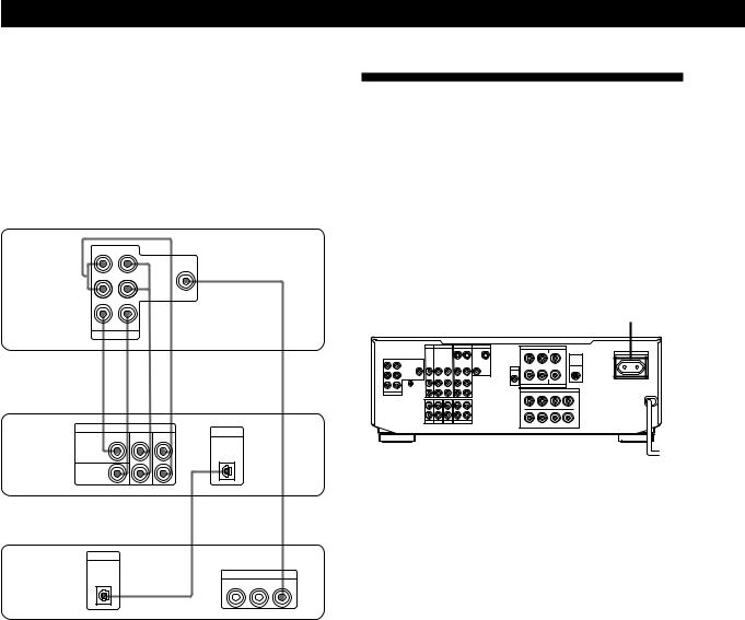
AC Hookups
Connecting the AC power cord
Connect the AC power cord from this amplifier and from your audio/video components to a wall outlet. If you connect another audio component to AC OUTLET on the amplifier, the amplifier can supply power to the connected component so you can turn on/off whole system when you turn on/off the amplifier.
AC OUTLET
|
|
TV / LD |
VIDEO 2 |
VIDEO 1 |
MONITOR |
||
|
|
|
|
|
OUT |
IN |
OUT |
FRONT |
REAR |
|
|
|
|
|
|
|
VIDEO |
VIDEO |
VIDEO |
VIDEO |
VIDEO |
VIDEO |
VIDEO |
L |
IN |
IN |
OUT |
IN |
OUT |
IN |
OUT |
R
|
AUDIO |
AUDIO |
AUDIO |
AUDIO |
AUDIO |
|
IN |
OUT |
IN |
OUT |
IN |
|
SIGNAL |
|
|
|
L |
|
GND |
|
|
|
|
CENTER WOOFER |
y |
|
|
|
|
5.1 INPUT |
|
|
|
|
R |
|
IN |
IN |
IN |
RECOUT |
IN |
|
|
|
|
|
L |
|
|
|
|
|
R |
|
PHONO |
TUNER |
CD |
TAPE / MD |
|
Caution
SURROUND SPEAKERS
R REAR L |
CENTER |
AC OUTLET
|
|
|
WIRELESS |
SWITCHED 100W MAX |
|
+ |
+ |
REAR |
|
|
|
|
SPEAKER |
|
WOOFER |
|
|
|
|
AUDIO |
– |
– |
|
|
OUT |
|
|
|
|
R L
IMPEDANCE USE 4–16 Ω
+ |
FRONT SPEAKERS |
+ |
|
– – |
Ω |
||
|
IMPEDANCE USE 4–16 |
|
|
A |
|
|
A |
R + |
– – |
|
+ L |
B |
|
|
B |
b
to a wall outlet
Make sure that the power consumption of the component connected to amplifier’s AC OUTLET does not exceed the wattage stated on the rear panel. Do not connect highwattage electrical home appliances such as electric irons, fans, or TVs to this outlet.
8EN

|
|
|
|
|
|
|
|
|
Getting Started |
|
Basic Operations Basic Operations |
|
|
|
|
|
|
|
|
|
|
|
|
Before You Use Your Amplifier
Before you start using your amplifier, make sure that you have:
•Turned MASTER VOLUME to the leftmost position
(0).
•Selected the appropriate speaker system. (For details, see “Selecting the speaker system” on page 6.)
•Set BALANCE to the center position.
Turn on the amplifier and check the following indicator.
•Press MUTING on the remote if “MUTING” appears in the display.
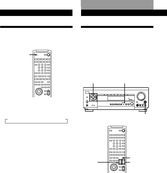
Clearing the amplifier’s memory
Before you use your amplifier for the first time or when you want to clear the amplifier’s memory, do the procedure below.
POWER |
|
|
AUDIO FUNCTION |
|
|
|
|
|
|
|
|
|
|
|
|
|||||||||
|
|
|
|
|
|
|
|
|
|
|
|
|
|
|
MASTER VOLUME |
|
|
|
|
|||||
|
|
|
|
|
|
|
|
|
|
|
|
|
|
|
• |
• |
• 5 |
• |
• |
• |
|
|
|
|
|
POWER |
TONE |
|
|
|
|
|
|
|
|
|
• |
4 |
|
|
|
|
|
|
6 |
• |
|
|
|
|
|
|
|
|
|
|
|
|
|
|
|
|
|
|
|
|
|
|
|
• |
|
|
||
|
|
SUR |
INDEX |
|
|
|
|
|
|
|
|
|
• |
|
|
|
|
|
|
|
|
|
• |
|
|
|
|
VIDEO 1 |
VIDEO 2 |
VIDEO 3 |
TV/LD |
TAPE/MD |
CD |
|
TUNER |
PHONO |
3 |
|
|
|
|
|
|
|
|
|
|
7 |
|
|
|
|
|
|
|
|
|
|
|
|
|
|
• |
|
|
|
|
|
|
|
|
|
|
• |
|
|
|
|
|
|
|
|
|
|
|
|
|
• |
|
|
|
|
|
|
|
|
|
|
• |
|
DPC |
|
|
|
|
|
|
|
|
|
|
|
• |
|
|
|
|
|
|
|
|
|
|
• |
|
MODE |
|
|
|
|
|
|
|
|
|
|
|
2 |
|
|
|
|
|
|
|
|
|
|
8 |
|
|
|
|
|
|
|
|
|
|
|
|
|
• |
|
|
|
|
|
|
|
|
|
|
• |
|
|
|
|
|
|
|
|
|
|
|
|
|
• |
|
|
|
|
|
|
|
|
|
|
• |
|
|
|
|
|
|
|
|
|
|
|
|
DIRECT PASS |
• |
|
|
|
|
|
|
|
|
|
|
• |
|
|
|
|
|
|
|
|
|
|
|
|
|
1 |
|
|
|
|
|
|
|
|
|
|
9 |
SPEAKERS |
g |
|
|
|
|
|
|
|
|
5.1 INPUT |
• |
|
|
|
|
|
|
|
|
|
• |
|
||
|
|
|
|
|
|
|
|
• |
|
|
|
|
|
|
|
|
|
|
|
|||||
OFF |
A |
B |
|
|
|
|
|
|
|
|
|
• |
0 |
|
|
|
|
|
|
10 |
• |
• |
BALANCE |
|
A+B |
|
|
|
|
|
|
|
|
|
|
|
|
BASS |
|
|
|
|
|
|
|
||||
|
|
|
|
|
|
|
|
DIRECT |
|
|
SOUND FIELD |
BOOST |
|
|
|
|
|
|
|
|
|
|
|
|
|
|
|
|
|
|
|
|
|
PASS |
SET UP |
|
ON / OFF |
|
|
|
|
|
|
|
|
|
|
|
|
|
|
|
|
|
VIDEO FUNCTION |
AUDIO FUNCTION |
|
5.1 |
GENRE |
MODE |
|
|
|
|
|
|
|
|
|
L |
|
R |
||
PHONES |
|
|
INPUT |
|
|
|
|
|
VIDEO 3 INPUT |
|
|
|
||||||||||||
|
|
DIMMER |
DISPLAY |
|
|
|
|
|
|
|
|
|
|
|
|
|
|
|
|
|
|
|
|
|
|
|
|
|
|
|
|
|
|
|
|
|
|
S VIDEO |
|
|
VIDEO |
|
L |
|
AUDIO |
R |
|
||
|
VIDEO FUNCTION |
MODE |
1 |
Turn off the amplifier. |
|
2 |
Press down VIDEO FUNCTION , AUDIO |
|
|
FUNCTION , MODE, and POWER |
|
simultaneously.
The contents of the memory (e. g., parameter settings) are erased.
Selecting a Component
To listen to or watch a connected component, first select the function on the amplifier or with the remote. Before you begin, make sure you have:
•Connected all components securely and correctly as indicated on pages 4 to 8.
•Turned MASTER VOLUME to the leftmost position
(0) to avoid damaging your speakers.
Digital processing
SPEAKERS |
control buttons |
|
|
|
|
|
|
|
|
|
|
|
|
|
|
|
POWER |
DIRECT PASS |
SET UP MASTER VOLUME |
||||||||||||||
|
|
|
|
|
|
|
|
MASTER VOLUME |
|
|
|
|
||||
|
|
|
|
|
|
|
|
• • |
• 5 |
• |
• |
• |
|
|
|
|
POWER |
|
|
|
|
|
• |
4 |
|
|
|
|
|
6 |
• |
|
|
TONE |
|
|
|
|
|
|
|
|
|
|
|
|
|
• |
|
|
SUR |
INDEX |
|
|
|
|
• |
|
|
|
|
|
|
|
|
• |
|
|
VIDEO 1 VIDEO 2 VIDEO 3 TV/LD |
TAPE/MD |
CD |
TUNER |
PHONO |
3 |
|
|
|
|
|
|
|
|
|
7 |
|
|
|
|
|
|
• |
|
|
|
|
|
|
|
|
|
• |
|
|
|
|
|
|
• |
|
|
|
|
|
|
|
|
|
• |
DPC |
|
|
|
|
|
• |
|
|
|
|
|
|
|
|
|
• |
MODE |
|
|
|
|
|
2 |
|
|
|
|
|
|
|
|
|
8 |
|
|
|
|
|
|
• |
|
|
|
|
|
|
|
|
|
• |
|
|
|
|
|
|
• |
|
|
|
|
|
|
|
|
|
• |
|
|
|
|
|
DIRECT PASS |
• |
|
|
|
|
|
|
|
|
|
• |
|
|
|
|
|
|
1 |
|
|
|
|
|
|
|
|
|
9 |
SPEAKERS |
g |
|
|
|
5.1 INPUT |
• |
|
|
|
|
|
|
|
|
• |
|
|
|
|
• |
|
|
|
|
|
|
|
|
|
|
|||
OFF A B |
|
|
|
|
• |
0 |
|
|
|
|
|
10 |
• |
• |
BALANCE |
|
A+B |
|
|
|
|
|
BASS |
|
|
|
|
|
|
||||
|
|
|
DIRECT |
SOUND FIELD |
BOOST |
|
|
|
|
|
|
|
|
|
|
|
|
|
|
|
PASS SET UP |
ON / OFF |
|
|
|
|
|
|
|
|
|
|
|
|
VIDEO FUNCTION |
AUDIO FUNCTION |
5.1 |
GENRE MODE |
|
|
|
|
|
|
|
|
L |
|
R |
|
PHONES |
INPUT |
|
|
|
VIDEO 3 INPUT |
|
|
|
||||||||
DIMMER DISPLAY |
|
|
|
|
|
|
|
|
|
|
|
|
|
|
|
|
|
|
|
|
|
|
S VIDEO |
|
VIDEO |
|
L |
|
AUDIO |
R |
|
||
|
VIDEO/AUDIO |
|
|
|
|
|
|
|
|
|
|
|
|
|
|
|
DIMMER FUNCTION |
|
5.1 INPUT |
BASS |
|
|
|
|
BALANCE |
||||||||
PHONES |
|
|
|
|
|
BOOST |
|
|
|
|
|
|
||||
|
|
|
|
|
|
|
|
|
|
|
|
|
|
|
|
|
1Press POWER to turn on the amplifier. The STANDBY indicator turns off.
2Select the component you want to use:
To watch or |
Press |
To light up |
listen to |
(repeatedly) |
|
|
|
|
Video tapes |
VIDEO |
VIDEO 1 or VIDEO 2 |
|
FUNCTION |
|
|
|
|
Video camera |
VIDEO |
VIDEO 3 |
recorder or video |
FUNCTION |
|
game |
|
|
|
|
|
Laser discs |
VIDEO |
TV/LD |
|
FUNCTION |
|
|
|
|
TV programs |
VIDEO |
TV/LD |
|
FUNCTION |
|
|
|
|
Audio tapes |
AUDIO |
TAPE/MD |
|
FUNCTION |
|
|
|
|
MiniDiscs (MD) |
AUDIO |
TAPE/MD |
|
FUNCTION |
|
|
|
|
Compact Discs (CD) AUDIO |
CD |
|
|
FUNCTION |
|
|
|
|
(Continued)
9EN

Basic Operations
To watch or |
Press |
To light up |
listen to |
(repeatedly) |
|
|
|
|
Radio programs |
AUDIO |
TUNER |
|
FUNCTION |
|
|
|
|
Records |
AUDIO |
PHONO |
|
FUNCTION |
|
|
|
|
3Turn on the component, for example, a CD player, and then start playing.
4Turn MASTER VOLUME to adjust the volume. To adjust the volume of the TV’s speakers, use the volume control on the TV.
To play the decoded Dolby Digital (AC-3) program source connected to the 5.1 INPUT jacks
Press 5.1 INPUT so that the 5.1 INPUT indicator lights up.
To |
Do this |
Mute the sound Z |
Press MUTING on the remote. Press |
|
again to restore the sound. |
|
|
Reinforce the bass |
Press BASS BOOST to turn on the |
|
BASS BOOST indicator |
|
|
Adjust the balance of |
Turn BALANCE left or right |
front speakers |
|
|
|
zWhen you listen with headphones
Connect the headphones to the PHONES jack and set SPEAKERS to OFF.
zWhen you want to enjoy high quality sound
Press DIRECT PASS (or DIRECT on the remote) to bypass the tone controls, bass reinforcement, and surrround effects.
The DIRECT PASS indicator lights up.
zTo select another component when a decoded Dolby Digital (AC-3) program source is selected
Press VIDEO/AUDIO FUNCTION to turn off the 5.1 INPUT indicator.
Note
BASS BOOST, DIRECT PASS, and SOUND FIELD ON/ OFF buttons do not operate when the 5.1 INPUT indicator is on.
zYou can adjust the brightness of the display
Press DIMMER repeatedly to select the brightness.
Watching TV/video programs
To watch |
Do this |
TV programs |
Turn on both the TV and the amplifier |
|
and press VIDEO FUNCTION |
|
repeatedly until the TV/LD indicator |
|
lights up |
Videos or laser discs 1 Press VIDEO FUNCTION repeatedly to select the component (for example, VIDEO 1).
2Turn on the TV and set the TV’s video input to match your video component.
3Turn on the component (VCR or LD player), and start playback.
zWhen you watch TV or video programs
We recommend you play audio portion through the amplifier instead of your TV’s speakers. This lets you take advantage of the amplifier’s surround sound effects, like Dolby Surround, and lets you use the amplifier’s remote to control the audio.
Turn off the speakers on your TV before you start so you can enjoy the surround sound from your amplifier.
10EN
Using the remote Z
The remote lets you operate the amplifier and the Sony components that are connected to it.
|
|
|
|
VISUALSYSTEM OFF |
SYSTEM OFF |
|
|
SLEEP |
|
|
POWER |
|
|
|
|
|
|
|
|
|
|
|
SYSTEM CONTROL / FUNCTION |
|
|||
|
VIDEO 1 |
VIDEO 2 |
VIDEO 3 |
LD |
TV |
SYSTEM |
|
TAPE |
DAT/MD |
CD |
TUNER |
PHONO |
|
|
|
(AUTO CATEGORIZE SYSTEM) |
|
CONTROL/ |
||
|
ON |
|
|
|
5.1 |
|
TV CONTROL |
TV |
|
|
|
|
|
CONTROL |
|
|
INPUT |
|
||
|
1 |
2 |
3 |
|
FUNCTION |
|
ON |
|
4 |
5 |
6 |
TV/VIDEO |
|
|
|
|
|
DISC |
|
|
|
|
|
|
|
D.TUNING |
|
|
|
7 |
8 |
9 |
+ |
|
>10 |
0 |
– |
5.1 INPUT |
BACK |
|
CH/ |
|
GROUND SHIFT |
ENTER |
PRESET |
|
|
RMS/START |
ANT |
|
– SUB CH + |
POSITION SWAP |
|
|
TV/VTR |
|
0 
 )
) 
 =
=
 +
+ 
 D. SKIP
—RMS —
DIRECTION |
CLEAR |
P IN P |
JUMP |
|
9 |
( |
p |
P |
r |
— SOUND FIELD — |
|
TEST |
||
ON/OFF |
GENRE |
MODE |
|
TONE |
EQ/ |
BAND |
SLOPE |
— LEVEL — |
|
TONE |
||||
|
|
|
+ |
+ |
DIGTAL |
|
DIRECT |
REAR |
CENTER |
PROCESSING |
|
– |
– |
|
CONTROL |
|
|||
MASTER
BASS VOL
BOOST
DPC
MODE
MUTING
PROGRAMMABLE
1Press one of the SYSTEM CONTROL/ FUNCTION buttons to select the component you want to use.
The amplifier and the selected component turn on. The SYSTEM CONTROL/FUNCTION buttons on the remote are factory-set as follows:
To play |
Press |
|
|
Video tapes |
VIDEO 1 (VTR 3*), |
|
VIDEO 2 (VTR 1*) or |
|
VIDEO 3 (VTR 2*) |
Laser discs |
LD |
|
|
TV programs |
TV |
|
|
Audio tapes |
TAPE |
|
|
MiniDiscs (MD) |
DAT/MD |
|
|
Compact Discs (CD) |
CD |
|
|
Radio programs |
TUNER |
|
|
Records |
PHONO |
*Sony VCRs are operated with a VTR 1, 2, or 3 setting that corresponds to Beta, 8mm, and VHS, respectively.
Basic Operations
Note
Pressing a SYSTEM CONTROL/FUNCTION button will activate the component indicated for that button (i.e., the component connected to the respective connector). If, however, the connected component is different from the one indicated for the button, the component will not be activated when the button is pressed only once.
For example, to watch Sony LD player connected to the VIDEO 2 jacks (page 7):
Press VIDEO 2 to switch the function, then press LD to set the remote control to operate the LD player.
To play the decoded Dolby Digital (AC-3) program source connected to the 5.1 INPUT jacks
Press 5.1 INPUT so that the 5.1 INPUT indicator on the main unit lights up.
If you want to change the factory setting of a button
See page 20.
If the component does not turn on
Press the power switch on the component.
2Start playing.
See “Remote Button Descriptions” on page 26 for details.
To turn off the components
Press SYSTEM OFF. This will also turn off the video/ audio component connected to AC OUTLET on the back of this unit at the same time.
zIf you use a Sony TV
When you press TV to watch a TV program, the TV turns on and switches to the TV input. The TV also turns on automatically and switches to the appropriate video input when you press VIDEO 1 or VIDEO 2. If the TV does not switch to the appropriate input automatically, press TV/VIDEO on the remote.
zWatching TV without the amplifier (for Sony TVs only)
Press TV CONTROL ON to set the remote to operate TV functions only. When you press this button, the TV turns on and switches to the TV input. If the TV does not automatically switch to the TV input, press TV/ VIDEO.
(Continued)
11EN
Basic Operations
zTo select another component when a decoded Dolby Digital (AC-3) program source is selected
Press any SYSTEM CONTROL/FUNCTION button to turn off the 5.1 INPUT indicator on the main unit.
Making components selectable/ unselectable
You can do these settings so that certain components become unselectable even if you press AUDIO/VIDEO FUNCTION.
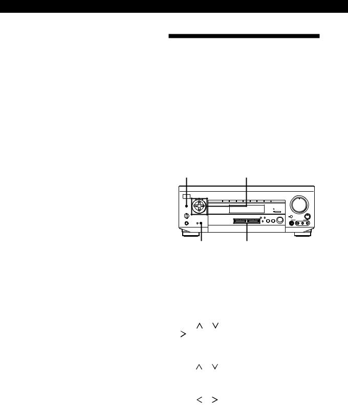
1Press SET UP repeatedly to select FUNC HOOK UP.
2Use the digital processing control buttons (  /
/  ) to select a component.
3Use the digital processing control buttons (  /
/  ) to select –Y– (selectable) or –N– (unselectable).
Note
If you try to select the component which is set to –N– by using the remote, “CANNOT USE” appears in the display.
Indexing Program Sources
You can enter a name of up to 8 characters for program sources. These index names (for example, “VHS”) appear in the amplifier’s display when a program source is selected.
Note that no more than one name can be entered for each program source.
This function is useful for distinguishing components of the same kind; 2 VCRs, for example, can be specified as “VHS” and “8MM,” respectively. It is also handy for identifying components connected to jacks meant for another type of component; for example, a second CD player connected to the TUNER jacks.
|
Digital processing |
DPC MODE |
control buttons |
|
|
|
|
|
|
|
|
|
|
|
|
|
MASTER VOLUME |
|
|
|
||||||
|
|
|
|
|
|
|
|
|
|
|
|
|
• |
• |
• |
5 |
• |
• |
• |
|
|
|
|
POWER |
|
TONE |
|
|
|
|
|
|
|
• |
4 |
|
|
|
|
|
|
|
6 |
• |
|
|
|
|
|
|
|
|
|
|
|
|
|
|
|
|
|
|
|
|
|
• |
|
|
|
|
SUR |
INDEX |
|
|
|
|
|
|
|
• |
|
|
|
|
|
|
|
|
|
• |
|
|
|
|
VIDEO 1 |
VIDEO 2 |
VIDEO 3 |
TV/LD |
TAPE/MD |
CD |
TUNER |
PHONO |
3 |
|
|
|
|
|
|
|
|
|
|
7 |
|
|
|
|
|
|
|
|
|
|
|
• |
|
|
|
|
|
|
|
|
|
|
• |
|
|
|
|
|
|
|
|
|
|
|
• |
|
|
|
|
|
|
|
|
|
|
• |
|
DPC |
|
|
|
|
|
|
|
|
|
• |
|
|
|
|
|
|
|
|
|
|
• |
|
MODE |
|
|
|
|
|
|
|
|
|
2 |
|
|
|
|
|
|
|
|
|
|
8 |
|
|
|
|
|
|
|
|
|
|
|
• |
|
|
|
|
|
|
|
|
|
|
• |
|
|
|
|
|
|
|
|
|
|
|
• |
|
|
|
|
|
|
|
|
|
|
• |
|
|
|
|
|
|
|
|
|
|
DIRECT PASS |
• |
|
|
|
|
|
|
|
|
|
|
• |
|
|
|
|
|
|
|
|
|
|
|
1 |
|
|
|
|
|
|
|
|
|
|
9 |
SPEAKERS |
g |
|
|
|
|
|
|
5.1 INPUT |
• |
|
|
|
|
|
|
|
|
|
• |
|
||
|
|
|
|
|
|
• |
|
|
|
|
|
|
|
|
|
|
|
|||||
OFF |
A |
B |
|
|
|
|
|
|
|
• |
|
|
|
|
|
|
|
|
|
• |
|
|
A+B |
|
|
|
|
|
|
|
|
|
|
BASS |
0 |
|
|
|
|
|
|
|
10 |
• |
BALANCE |
|
|
|
|
|
|
|
|
|
|
BOOST |
|
|
|
|
|
|
|
|
|
|
|
|
|
|
|
DIRECT |
|
SOUND FIELD |
|
|
|
|
|
|
|
PASS |
SET UP |
ON / OFF |
|
|
|
|
|
VIDEO FUNCTION |
AUDIO FUNCTION |
5.1 |
GENRE |
MODE |
|
|
L |
R |
PHONES |
|
|
|
|
|
VIDEO 3 INPUT |
|
|
|
DIMMER |
DISPLAY |
|
|
|
|
|
|
|
|
|
|
|
|
|
S VIDEO |
VIDEO |
L |
AUDIO |
R |
DISPLAY |
VIDEO/AUDIO FUNCTION |
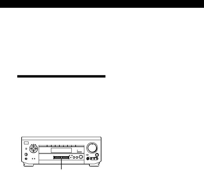
1Select the program source (component) to be named.
2Press DPC MODE repeatedly until the INDEX indicator lights up.
3Create an index name by using the digital processing control buttons as follows:
Press or to select a character, and then press to move the cursor to the next position.
The index name is stored automatically.
To insert a space
Press or until a blank space appears in the display (the space is between “]” and “A”).
If you’ve made a mistake
Press or repeatedly until the character you want to change flashes. Then select the right character.
To assign index names to other sources
Repeat the procedure above.
12EN
Basic Operations
zYou can display either the program source name or component originally meant for the selected jacks
Each time you press DISPLAY, the display switches between the component originally meant for the selected jacks and the program source name.
zYou can create an index name for the component connected to the 5.1 INPUT jacks
Press 5.1 INPUT and do the procedure on page 12 starting from Step 2.
Recording
This amplifier makes it easy to record to and from the components connected to the amplifier. You don’t have to connect playback and recording components directly: once you select a program source on the amplifier, you can record and edit as you normally would using the controls on each component.
Before you begin, make sure you’ve connected all components properly.
|
|
|
|
|
|
|
|
|
|
|
|
MASTER VOLUME |
|
|
|
||||||
|
|
|
|
|
|
|
|
|
|
|
|
• |
• |
• |
5 |
• |
• |
• |
|
|
|
POWER |
TONE |
|
|
|
|
|
|
|
|
• |
4 |
|
|
|
|
|
|
|
6 |
• |
|
|
|
|
|
|
|
|
|
|
|
|
|
|
|
|
|
|
|
|
• |
|
|
SUR |
INDEX |
|
|
|
|
|
|
|
|
• |
|
|
|
|
|
|
|
|
|
• |
|
|
VIDEO 1 |
VIDEO 2 |
VIDEO 3 |
TV/LD |
TAPE/MD |
CD |
TUNER |
PHONO |
|
3 |
|
|
|
|
|
|
|
|
|
|
7 |
|
|
|
|
|
|
|
|
|
|
• |
|
|
|
|
|
|
|
|
|
|
• |
|
|
|
|
|
|
|
|
|
|
• |
|
|
|
|
|
|
|
|
|
|
• |
DPC |
|
|
|
|
|
|
|
|
|
• |
|
|
|
|
|
|
|
|
|
|
• |
MODE |
|
|
|
|
|
|
|
|
|
2 |
|
|
|
|
|
|
|
|
|
|
8 |
|
|
|
|
|
|
|
|
|
|
• |
|
|
|
|
|
|
|
|
|
|
• |
|
|
|
|
|
|
|
|
|
|
• |
|
|
|
|
|
|
|
|
|
|
• |
|
|
|
|
|
|
|
|
|
DIRECT PASS |
• |
|
|
|
|
|
|
|
|
|
|
• |
|
|
|
|
|
|
|
|
|
|
1 |
|
|
|
|
|
|
|
|
|
|
9 |
SPEAKERS |
g |
|
|
|
|
|
|
|
5.1 INPUT |
• |
|
|
|
|
|
|
|
|
|
• |
|
|
|
|
|
|
|
|
• |
|
|
|
|
|
|
|
|
|
|
|
|||
OFF A B |
|
|
|
|
|
|
|
|
• |
|
|
|
|
|
|
|
|
|
• |
|
|
A+B |
|
|
|
|
|
|
|
|
|
BASS |
0 |
|
|
|
|
|
|
|
10 |
• |
BALANCE |
|
|
|
|
|
|
DIRECT |
|
|
SOUND FIELD |
|
|
|
|
|
|
|
|
|
|
|
|
|
|
|
|
|
|
PASS |
SET UP |
|
ON / OFF |
|
|
|
|
|
|
|
|
|
|
|
|
|
VIDEO FUNCTION |
AUDIO FUNCTION |
5.1 |
GENRE |
MODE |
|
|
L |
R |
PHONES |
|
|
|
|
|
VIDEO 3 INPUT |
|
|
|
DIMMER |
DISPLAY |
|
|
|
|
|
|
|
|
|
|
|
|
|
S VIDEO |
VIDEO |
L |
AUDIO |
R |
|
|
|
|
|
|
|
|
VIDEO/AUDIO FUNCTION |
|
|
|
|
|
|
||
|
|
|
|
|
|
|
|
|
|
|
|
|
|
|||
ç |
c |
|
|
|
|
ç |
|
c |
||||||||
|
|
|
|
|
|
|
|
|
|
|
|
|
|
|
|
|
|
Playback component |
|
Recording component |
|||||||||||||
|
|
(program source) |
|
(tape deck, MD deck, |
||||||||||||
|
|
|
|
|
|
|
|
|
|
VCR) |
|
|
|
|
||
ç: Audio signal flow |
|
|
|
|
||||||||||||
|
|
|
|
|
|
|
|
|||||||||
|
|
|
|
|
|
|
|
|||||||||
c: Video signal flow |
|
|
|
|
|
|
|
|
||||||||
Recording on an audio tape or MiniDisc
You can record on a cassette tape or MiniDisc using the amplifier. See the instruction manual of your cassette deck or MD deck if you need help.
1Select the component to be recorded.
2Set the component to be ready for playing. For example, insert a CD into the CD player.
3Insert a blank tape or an MD into the recording deck and adjust the recording level, if necessary.
4Start recording on the recording deck and then start playing the component.
Note
Sound adjustments do not affect the signal output from the TAPE/MD RECOUT jacks.
Recording on a video tape
You can record from a VCR, a TV, or an LD player using the amplifier. You can also add audio from a variety of audio sources when editing a video tape. See your VCR or LD player’s instruction manual if you need help.
1Select the program source to be recorded.
2Set the component to be ready for playing. For example, insert the laser disc you want to record from into the LD player.
3Insert a blank video tape into the VCR (VIDEO 1 or VIDEO 2) for recording.
4Start recording on the recording VCR and then start playing the video tape or laser disc you want to record.
zYou can record sound from a different audio source onto a video tape while copying from a video tape or laser disc
Locate the point where you want to start recording from another audio source, select the program source, then start playback. The audio from that source will be recorded onto the audio track of the video tape instead of the audio from the original.
To resume audio recording from the original, select the video source again.
Notes
•You cannot record audio from a program source connected to the 5.1 INPUT jacks.
•Sound adjustments do not affect the signal output from the VIDEO 1, 2 AUDIO OUT jacks.
13EN
BasicDolbyOperationsSur ound Setup
Using the Sleep Timer Z
You can set the amplifier to turn off automatically at a time you specify.
VISUALSYSTEM OFF
SLEEP |
SLEEP |
|
|
POWER |
|
|
|
SYSTEM CONTROL / FUNCTION |
|
||
|
VIDEO 1 |
VIDEO 2 |
VIDEO 3 |
LD |
TV |
|
|
(AUTO CATEGORIZE SYSTEM) |
|
||
|
TAPE |
DAT/MD |
CD |
TUNER |
PHONO |
|
TV |
|
|
|
5.1 |
|
CONTROL |
2 |
3 |
INPUT |
|
|
ON |
1 |
|
||
|
|
4 |
5 |
6 |
TV/VIDEO |
|
|
|
|||
|
|
|
|
|
D.TUNING |
|
|
7 |
8 |
9 |
DISC |
|
|
+ |
|||
|
BACK |
|
|
|
CH/ |
|
GROUND |
SHIFT |
0 |
ENTER |
PRESET |
|
|
>10 |
|
– |
|
|
|
|
|
RMS/START |
|
|
– SUB CH + |
POSITION SWAP |
ANT |
||
|
TV/VTR |
||||
0 
 )
) 
 =
=
 +
+ 
 D. SKIP
—RMS —
DIRECTION |
CLEAR |
P IN P |
JUMP |
|
9 |
( |
p |
P |
r |
— SOUND FIELD — |
|
TEST |
||
ON/OFF |
GENRE |
MODE |
|
TONE |
EQ/ |
BAND |
SLOPE |
— LEVEL — |
|
TONE |
||||
|
|
|
+ |
+ |
DIGTAL |
|
DIRECT |
REAR |
CENTER |
PROCESSING |
|
– |
– |
|
CONTROL |
|
|||
|
|
|
BASS |
MASTER |
|
|
|
VOL |
|
|
|
|
BOOST |
|
|
DPC |
|
|
|
|
MODE |
|
|
|
|
|
|
MUTING |
|
PROGRAMMABLE |
|
|
|
|
Press SLEEP on the remote while the power is on. Each time you press SLEEP, the time changes as shown below.
n2-00-00 n1-30-00n1-00-00 n0-30-00 nOFF
The display dims after you specify the time.
zYou can freely specify the time
Press SLEEP first, then specify the time you want using the digital processing control buttons (  or
or  ). The sleep time changes in 1 minute intervals. You can
specify up to 5 hours.
zYou can check the time remaining before the amplifier turns off
Press SLEEP. The remaining time appears in the display.
Dolby Surround Setup
Dolby Pro Logic
To obtain the best possible Dolby Pro Logic Surround sound, first select the center mode according to your speaker system. Then, adjust the sound parameters of the PRO LOGIC sound field.
Note that you must have at least one additional pair of speakers and/or one center speaker to do the following adjustments.
Digital processing |
|
control buttons |
SET UP |
|
|
|
|
|
|
|
|
|
|
|
|
|
|
|
MASTER VOLUME |
|
|
|
|
|||||
|
|
|
|
|
|
|
|
|
|
|
|
|
|
|
• |
• |
• 5 |
• |
• |
• |
|
|
|
|
|
POWER |
TONE |
|
|
|
|
|
|
|
|
|
• |
4 |
|
|
|
|
|
|
6 |
• |
|
|
|
|
|
|
|
|
|
|
|
|
|
|
|
|
|
|
|
|
|
|
|
• |
|
|
||
|
|
SUR |
INDEX |
|
|
|
|
|
|
|
|
|
• |
|
|
|
|
|
|
|
|
|
• |
|
|
|
|
VIDEO 1 |
VIDEO 2 |
VIDEO 3 |
TV/LD |
TAPE/MD |
CD |
|
TUNER |
PHONO |
3 |
|
|
|
|
|
|
|
|
|
|
7 |
|
|
|
|
|
|
|
|
|
|
|
|
|
|
• |
|
|
|
|
|
|
|
|
|
|
• |
|
|
|
|
|
|
|
|
|
|
|
|
|
• |
|
|
|
|
|
|
|
|
|
|
• |
|
DPC |
|
|
|
|
|
|
|
|
|
|
|
• |
|
|
|
|
|
|
|
|
|
|
• |
|
MODE |
|
|
|
|
|
|
|
|
|
|
|
2 |
|
|
|
|
|
|
|
|
|
|
8 |
|
|
|
|
|
|
|
|
|
|
|
|
|
• |
|
|
|
|
|
|
|
|
|
|
• |
|
|
|
|
|
|
|
|
|
|
|
|
|
• |
|
|
|
|
|
|
|
|
|
|
• |
|
|
|
|
|
|
|
|
|
|
|
|
DIRECT PASS |
• |
|
|
|
|
|
|
|
|
|
|
• |
|
|
|
|
|
|
|
|
|
|
|
|
|
1 |
|
|
|
|
|
|
|
|
|
|
9 |
SPEAKERS |
g |
|
|
|
|
|
|
|
|
5.1 INPUT |
• |
|
|
|
|
|
|
|
|
|
• |
|
||
|
|
|
|
|
|
|
|
• |
|
|
|
|
|
|
|
|
|
|
|
|||||
OFF |
A |
B |
|
|
|
|
|
|
|
|
|
• |
0 |
|
|
|
|
|
|
10 |
• |
• |
BALANCE |
|
A+B |
|
|
|
|
|
|
|
|
|
|
|
|
BASS |
|
|
|
|
|
|
|
||||
|
|
|
|
|
|
|
|
DIRECT |
|
|
SOUND FIELD |
BOOST |
|
|
|
|
|
|
|
|
|
|
|
|
|
|
|
|
|
|
|
|
|
PASS |
SET UP |
|
ON / OFF |
|
|
|
|
|
|
|
|
|
|
|
|
|
|
|
|
|
VIDEO FUNCTION |
AUDIO FUNCTION |
|
5.1 |
GENRE |
MODE |
|
|
|
|
|
|
|
|
|
L |
|
R |
||
PHONES |
|
|
INPUT |
|
|
|
|
|
VIDEO 3 INPUT |
|
|
|
||||||||||||
|
|
DIMMER |
DISPLAY |
|
|
|
|
|
|
|
|
|
|
|
|
|
|
|
|
|
|
|
|
|
|
|
|
|
|
|
|
|
|
|
|
|
|
S VIDEO |
|
|
VIDEO |
|
L |
|
AUDIO |
R |
|
||
|
|
|
|
|
|
|
|
|
|
|
|
|
|
|
BALANCE |
|||||||||
|
|
|
VISUALSYSTEM OFF |
|
SLEEP |
|
|
POWER |
|
|
SYSTEM CONTROL / FUNCTION |
|
||
VIDEO 1 |
VIDEO 2 |
VIDEO 3 |
LD |
TV |
|
(AUTO CATEGORIZE SYSTEM) |
|
||
TAPE |
DAT/MD |
CD |
TUNER |
PHONO |
TV |
|
|
|
5.1 |
CONTROL |
2 |
3 |
INPUT |
|
ON |
1 |
|
||
|
4 |
5 |
6 |
TV/VIDEO |
|
|
|||
|
|
|
|
D.TUNING |
|
7 |
8 |
9 |
DISC |
|
+ |
|||
BACK |
|
|
|
CH/ |
GROUND |
SHIFT |
0 |
ENTER |
PRESET |
|
>10 |
|
– |
|
|
|
|
RMS/START |
|
– SUB CH + |
POSITION SWAP |
ANT |
||
TV/VTR |
||||
0 
 )
) 
 =
=
 +
+ 
 D. SKIP
—RMS —
|
DIRECTION |
CLEAR |
P IN P |
JUMP |
|
|
|
9 |
( |
p |
P |
r |
|
|
— |
SOUND FIELD — |
|
TEST |
TEST TONE |
|
|
ON/OFF GENRE MODE |
|
TONE |
|||
|
EQ/ |
|
|
|
|
|
|
TONE BAND |
SLOPE |
— LEVEL — |
|
||
REAR |
|
|
|
+ |
+ |
CENTER |
CONTROL |
|
– |
– |
|||
|
DIGTAL |
DIRECT |
REAR |
CENTER |
|
|
LEVEL +/– |
PROCESSING |
|
|
|
LEVEL +/– |
|
|
|
|
BOOST |
MASTER |
||
|
|
|
|
BASS |
VOL |
|
|
|
DPC |
|
|
|
|
|
|
MODE |
|
|
|
|
|
|
|
|
MUTING |
|
|
|
PROGRAMMABLE |
|
|
|
|
|
14EN

Selecting the center mode
The amplifier offers you four center modes: PHANTOM, 3 CH LOGIC, NORMAL, and WIDE. Each mode is designed for a different speaker configuration. Select the mode that best suits your speaker system configuration.
1Press SET UP on the main unit repeatedly to select CTR MODE.
2Use the digital processing control buttons (  /
/  /
/  /
/  ) to select the center mode you want by referring to the following table.
If you have |
Select |
So that |
|
|
|
Front and rear |
PHANTOM |
The sound of the |
speakers, no center |
|
center channel is |
speaker |
|
output from the |
|
|
front speakers |
|
|
|
Front and center |
3 CH LOGIC |
The sound of the |
speakers, no rear |
(3 Channel |
rear channel is |
speaker |
Logic) |
output from the |
|
|
front speakers |
|
|
|
Front and rear |
NORMAL |
The bass sound of |
speakers, and a small |
|
the center channel |
center speaker |
|
is output from the |
|
|
front speakers |
|
|
(because a small |
|
|
speaker cannot |
|
|
produce enough |
|
|
bass) |
|
|
|
Front and rear |
WIDE |
You can obtain |
speakers, and a |
|
“complete” Dolby |
center speaker |
|
Pro Logic Surround |
equivalent to your |
|
sound |
front speakers |
|
|
|
|
|
Dolby Surround Setup
Adjusting the speaker volume Z
The test tone feature lets you set the volume of your speakers to the same level. (If all of your speakers have equal performance, you don’t have to adjust the speaker volume.)
Using the controls on the remote lets you adjust the volume level from your listening position.
1Do Steps 1 to 3 on page 16 to select the PRO LOGIC sound field.
2Make sure the center mode setting is correctly made (see the table on this page).
3Press TEST TONE on the remote.
You will hear the test tone from each speaker sequentially.
4Adjust the volume levels so that you hear the test tone from each speaker at the same volume level when you are in your listening position:
•To adjust the balance of the front right and front left speakers, use the BALANCE control on the front of the main unit.
•To adjust the level of center speaker, press CENTER LEVEL + or – on the remote.
•To adjust the level of rear speakers, press REAR LEVEL + or – on the remote.
5Press TEST TONE on the remote to turn off the test tone.
zYou can adjust all the speakers at one time
Press MASTER VOL + or – on the remote.
zYou can increase the output level of the rear speakers
You can raise the output of the rear speakers by 5 dB. When turning on the amplifier, press POWER and MODE simultaneously to display “GAIN UP.” To return the output level to normal, repeat this procedure to display “GAIN NORM.”
(Continued)
15EN
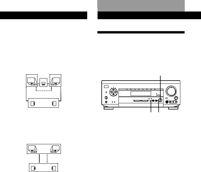
SDolbyundSurroundAdjustmentSetup
zWhat is the test tone?
Signal given out by the amplifier for adjusting the speaker volume. The test tone will come out as follows:
•In a system with a center speaker (NORMAL/WIDE/ 3 CH LOGIC modes)
The test tone is output from the front L (left), center, front R (right), and rear speakers in succession.
Front (L) |
Front (R) |
Center
3 CH LOGIC
Rear (L, R)
NORMAL/WIDE
•In a system without a center speaker (PHANTOM mode)
The test tone is output from the front and the rear speakers alternately.
Front (L, R)
PHANTOM
Rear (L, R)
Sound Adjustment
Using Pre-programmed Sound
Fields
You can take advantage of surround sound simply by selecting one of the pre-programmed sound fields according to the program you want to play.
SOUND FIELD ON/OFF
|
|
|
|
|
|
|
|
|
|
|
|
MASTER VOLUME |
|
|
|
|
|||||
|
|
|
|
|
|
|
|
|
|
|
|
• |
• |
• 5 |
• |
• |
• |
|
|
|
|
POWER |
|
|
|
|
|
|
|
|
|
|
4 |
|
|
6 |
|
|
|
||||
|
|
|
|
|
|
|
|
|
• |
|
|
|
|
|
|
• |
|
|
|||
TONE |
|
|
|
|
|
|
|
|
|
|
|
|
|
|
|
|
|
• |
|
|
|
SUR |
INDEX |
|
|
|
|
|
|
|
|
• |
|
|
|
|
|
|
|
|
|
• |
|
|
VIDEO 1 |
VIDEO 2 |
VIDEO 3 |
TV/LD |
TAPE/MD |
CD |
TUNER |
PHONO |
3 |
|
|
|
|
|
|
|
|
|
|
7 |
|
|
|
|
|
|
|
|
|
|
|
• |
|
|
|
|
|
|
|
|
|
|
• |
|
|
|
|
|
|
|
|
|
|
• |
|
|
|
|
|
|
|
|
|
|
• |
DPC |
|
|
|
|
|
|
|
|
|
• |
|
|
|
|
|
|
|
|
|
|
• |
MODE |
|
|
|
|
|
|
|
|
|
2 |
|
|
|
|
|
|
|
|
|
|
8 |
|
|
|
|
|
|
|
|
|
|
• |
|
|
|
|
|
|
|
|
|
|
• |
|
|
|
|
|
|
|
|
|
|
• |
|
|
|
|
|
|
|
|
|
|
• |
|
|
|
|
|
|
|
|
|
DIRECT PASS |
• |
|
|
|
|
|
|
|
|
|
|
• |
|
|
|
|
|
|
|
|
|
|
1 |
|
|
|
|
|
|
|
|
|
|
9 |
SPEAKERS |
g |
|
|
|
|
|
|
|
5.1 INPUT |
• |
|
|
|
|
|
|
|
|
|
• |
|
|
|
|
|
|
|
|
• |
|
|
|
|
|
|
|
|
|
|
|
|||
OFF A B |
|
|
|
|
|
|
|
|
• |
0 |
|
|
|
|
|
|
10 |
• |
• |
BALANCE |
|
A+B |
|
|
|
|
|
|
|
|
|
BASS |
|
|
|
|
|
|
|
||||
|
|
|
|
|
|
DIRECT |
|
SOUND FIELD |
BOOST |
|
|
|
|
|
|
|
|
|
|
|
|
|
|
|
|
|
|
|
PASS SET UP |
|
ON / OFF |
|
|
|
|
|
|
|
|
|
|
|
|
|
|
|
VIDEO FUNCTION |
AUDIO FUNCTION |
5.1 |
GENRE |
MODE |
|
|
|
|
|
|
|
|
|
L |
|
R |
||
PHONES |
|
|
INPUT |
|
|
|
|
|
VIDEO 3 INPUT |
|
|
|
|||||||||
DIMMER |
DISPLAY |
|
|
|
|
|
|
|
|
|
|
|
|
|
|
|
|
|
|
|
|
|
|
|
|
|
|
|
|
|
|
S VIDEO |
|
|
VIDEO |
|
L |
|
AUDIO |
R |
|
||
GENRE MODE
1Press SOUND FIELD ON/OFF to turn on the sound field.
One of the indicators lights up in the display.
2Press GENRE to select the type of sound field you desire.
3Press MODE to select the mode you desire from the respective genre.
Select the appropriate sound field according to the chart on page 17.
To play without surround effects
Select “ACOUSTIC” from MUSIC. The surround effects are defeated but you can still adjust the tone parameter (see page 18).
To turn off the sound fields
Press SOUND FIELD ON/OFF.
zYou can find Dolby Surround-encoded software by looking at the packaging
However, some videos and laser discs may use Dolby Surround sound even if it’s not indicated on the package.
Note
Sound fields are turned off whenever the program source connected to the 5.1 INPUT jacks is selected.
16EN
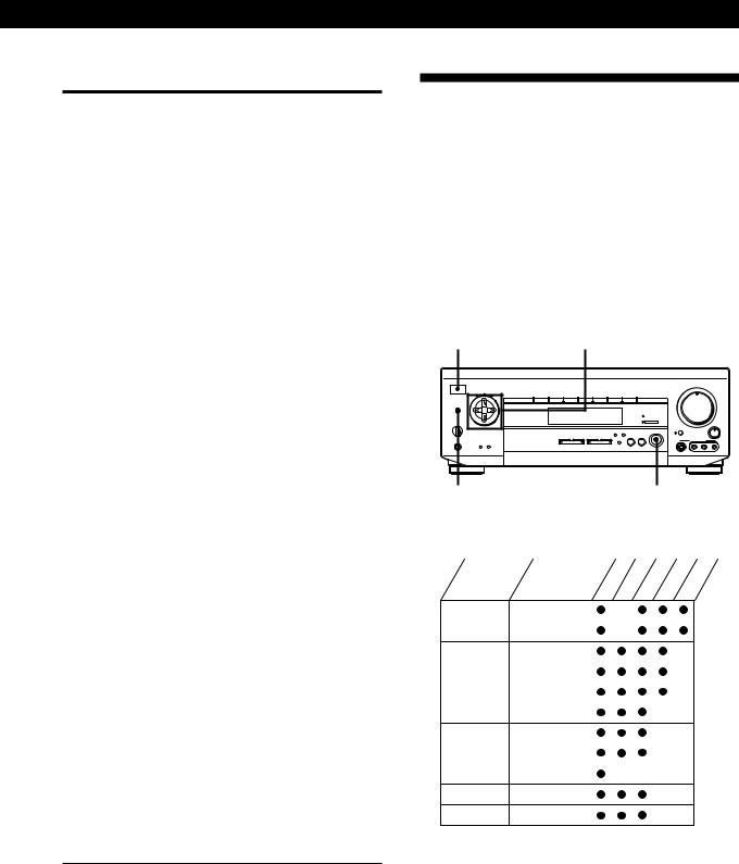
Sound Adjustment
Sound fields
GENRE |
MODE |
To |
|
PRO LOGIC* |
|
PRO LOGIC |
Decode programs |
|
|
|
processed with |
|
|
|
Dolby Surround |
|
|
|
|
|
|
ENHANCED |
Provide additional |
|
|
|
output to the rear |
|
|
|
speakers after |
|
|
|
decoding the Dolby |
|
|
|
Surround program |
|
|
|
|
MOVIE |
|
C(INEMA) STUDIO A Reproduce the |
|
|
|
|
acoustics of a sound |
|
|
|
stage of a studio |
|
|
|
producing regular |
|
|
|
movies |
|
|
|
|
|
|
C(INEMA) STUDIO B Reproduce the |
|
|
|
|
acoustics of a sound |
|
|
|
stage of a studio |
|
|
|
producing SFX or |
|
|
|
action movies with |
|
|
|
lots of sound effects |
|
|
|
|
|
|
THEATER |
Add the acoustic |
|
|
|
reflections of a |
|
|
|
theater to decoded |
|
|
|
Dolby Surround |
|
|
|
signals |
|
|
|
|
|
|
MONO MOVIE |
Create a theater-like |
|
|
|
environment from |
|
|
|
movies with |
|
|
|
monaural |
|
|
|
soundtracks |
|
|
|
|
MUSIC |
|
HALL |
Reproduce the |
|
|
|
acoustics of a hall |
|
|
|
|
|
|
JAZZ CLUB |
Reproduce the |
|
|
|
acoustics of a jazz |
|
|
|
club |
|
|
|
|
|
|
ACOUSTIC** |
Reproduce normal 2 |
|
|
|
channel stereo. (No |
|
|
|
surround effects) |
|
|
|
|
SPORTS |
|
STADIUM |
Reproduce the |
|
|
|
feeling of a large |
|
|
|
open-air stadium. |
|
|
|
Great for sporting |
|
|
|
events or electric |
|
|
|
sounds. |
|
|
|
|
GAME |
GAME |
Obtain maximum |
|
|
|
|
audio impact from |
|
|
|
video game software |
*Be sure to adjust the volume level of the center and/or rear speakers to get the most out of the Dolby Pro Logic Surround Sound (page 15).
**The hookups of the center and/or rear speakers are unnecessary.
Customizing the Sound Fields
Each sound field is composed of a tone parameter (bass/treble) and surround sound parameters — variables of sound that create the sound image. You can customize the sound fields by adjusting some of the sound parameters to suit your listening situation.
Once you customize the sound fields, they are stored in memory unless the amplifier is unplugged for about 1 week. To change a customized sound field, make new adjustments to the sound field.
|
Digital processing |
|
|
|
|
|
|
|
|
|
|
|
|
|
|||||
POWER |
control buttons |
|
|
|
|
|
|
|
|
|
|
|
|
|
|
||||
|
|
|
|
|
|
|
|
|
|
|
|
|
|
|
|
|
|
|
|
|
|
|
|
|
|
|
|
|
|
MASTER VOLUME |
|
|
|
|
|||||
|
|
|
|
|
|
|
|
|
|
• |
• |
• 5 |
• |
• |
• |
|
|
|
|
POWER |
|
|
|
|
|
|
|
• |
4 |
|
|
|
|
|
|
6 |
• |
|
|
TONE |
|
|
|
|
|
|
|
|
|
|
|
|
|
|
|
|
• |
|
|
SUR |
INDEX |
|
|
|
|
|
|
• |
|
|
|
|
|
|
|
|
|
• |
|
|
VIDEO 1 VIDEO 2 |
VIDEO 3 TV/LD |
TAPE/MD |
CD |
TUNER |
PHONO |
3 |
|
|
|
|
|
|
|
|
|
|
7 |
|
|
|
|
|
|
|
|
|
• |
|
|
|
|
|
|
|
|
|
|
• |
|
|
|
|
|
|
|
|
• |
|
|
|
|
|
|
|
|
|
|
• |
DPC |
|
|
|
|
|
|
|
• |
|
|
|
|
|
|
|
|
|
|
• |
MODE |
|
|
|
|
|
|
|
2 |
|
|
|
|
|
|
|
|
|
|
8 |
|
|
|
|
|
|
|
|
• |
|
|
|
|
|
|
|
|
|
|
• |
|
|
|
|
|
|
|
|
• |
|
|
|
|
|
|
|
|
|
|
• |
|
|
|
|
|
|
|
DIRECT PASS |
• |
|
|
|
|
|
|
|
|
|
|
• |
|
|
|
|
|
|
|
|
1 |
|
|
|
|
|
|
|
|
|
|
9 |
SPEAKERS |
g |
|
|
|
|
|
5.1 INPUT |
• |
|
|
|
|
|
|
|
|
|
• |
|
|
|
|
|
|
• |
|
|
|
|
|
|
|
|
|
|
|
|||
OFF A B |
|
|
|
|
|
|
• |
0 |
|
|
|
|
|
|
10 |
• |
• |
BALANCE |
|
A+B |
|
|
|
|
|
|
|
BASS |
|
|
|
|
|
|
|
||||
|
|
|
|
DIRECT |
|
SOUND FIELD |
BOOST |
|
|
|
|
|
|
|
|
|
|
|
|
|
|
|
|
|
|
|
|
|
|
|
|
|
|
|
|
|
|
||
|
|
|
|
|
PASS SET UP |
|
ON / OFF |
|
|
|
|
|
|
|
|
|
|
|
|
|
|
VIDEO FUNCTION |
AUDIO FUNCTION |
5.1 |
GENRE |
MODE |
|
|
|
|
|
|
|
|
|
L |
|
R |
|
PHONES |
|
INPUT |
|
|
|
|
|
VIDEO 3 INPUT |
|
|
|
||||||||
DIMMER DISPLAY |
|
|
|
|
|
|
|
|
|
|
|
|
|
|
|
|
|
|
|
|
|
|
|
|
|
|
|
S VIDEO |
|
|
VIDEO |
|
L |
|
AUDIO |
R |
|
||
DPC MODE |
|
|
|
SOUND FIELD ON/OFF |
|||||||||||||||
Adjustable parameters for each sound field
GENRE |
MODE |
TONE |
EFFECT |
REAR |
CENTER DELAY |
|||||
PRO LOGIC |
PRO LOGIC |
|
|
|
|
* |
|
** |
|
|
|
|
|
|
|
|
|
|
|
||
|
|
|
|
|
|
|
|
|
|
|
|
ENHANCED |
|
|
|
|
* |
|
** |
|
|
|
|
|
|
|
|
|
|
|
|
|
MOVIE |
C STUDIO A |
|
|
|
|
* |
|
** |
|
|
|
|
|
|
|
|
|
|
|
||
|
|
|
|
|
|
|
|
|
|
|
|
C STUDIO B |
|
|
|
|
* |
|
** |
|
|
|
|
|
|
|
|
|
|
|
|
|
|
|
|
|
|
|
|
|
|
|
|
|
THEATER |
|
|
|
|
* |
|
** |
|
|
|
|
|
|
|
|
|
|
|
|
|
|
MONO MOVIE |
|
|
|
|
|
|
|
|
|
MUSIC |
HALL |
|
|
|
|
|
|
|
|
|
|
|
|
|
|
|
|
|
|
|
|
|
JAZZ CLUB |
|
|
|
|
|
|
|
|
|
|
|
|
|
|
|
|
|
|
|
|
|
ACOUSTIC |
|
|
|
|
|
|
|
|
|
SPORTS |
STADIUM |
|
|
|
|
|
|
|
|
|
GAME |
GAME |
|
|
|
|
|
|
|
|
|
|
|
|
|
|
|
|
|
|
|
|
*Adjustable only when center mode is set to PHANTOM, NORMAL, or WIDE (see page 15).
**Adjustable only when center mode is set to 3 CH LOGIC, NORMAL, or WIDE (see page 15).
Note
The EFFECT parameter allows you to adjust the overall presence of the sound field.
17EN

Sound Adjustment
Before you get started
To take advantage of Dolby Surround sound, go to “Dolby Pro Logic” on page 14. This section describes how to adjust the levels of your speaker system and customize the PRO LOGIC sound field.
Adjusting the tone parameter
Adjust the tone (bass or treble) of the front speakers for optimum sound. You can adjust the tone of all sounds fields, including Dolby Surround.
1Press DPC MODE repeatedly until the TONE indicator lights up.
2Use the digital processing control buttons (  /
/  ) to select BASS or TREBLE.
3Use the digital processing control buttons (  /
/  ) to adjust the tone level.
The adjusted tone level is stored automatically.
zYou can turn off the tone adjustments without erasing them
The tone adjustments and on/off setting are stored separately for each sound field. Press DPC MODE repeatedly to turn off the TONE indicator.
Adjusting the delay time
You can make the surround sound more effective by delaying the output from the rear speakers (delay time). You can select a delay time of 15 ms (S), 20 ms (M), and 30 ms (L). Set a short delay time when the rear speakers are located in a large room or far from your listening position.
1Start playing a program source encoded with Dolby surround sound.
2Press DPC MODE repeatedly until the SUR indicator lights up.
3Use the digital processing control buttons (  /
/  ) to select the delay time.
The current delay time appears in the display.
4Use the digital processing control buttons (  /
/  ) to adjust the delay time.
Adjusting surround sound parameters
Change the surround parameters to fit your listening situation. See the chart on page 17 for parameters you can adjust in each sound field.
To adjust the parameters of the PRO LOGIC sound field, see “Dolby Pro Logic” on page 14.
1Press DPC MODE repeatedly until the SUR indicator lights up.
2Use the digital processing control buttons (  /
/  ) to select the parameter you want.
3Use the digital processing control buttons (  /
/  ) to adjust the level of the parameter.
The adjusted parameters are stored automatically.
Note
If you make new adjustments to a sound field, the previous settings are replaced by the new ones.
18EN
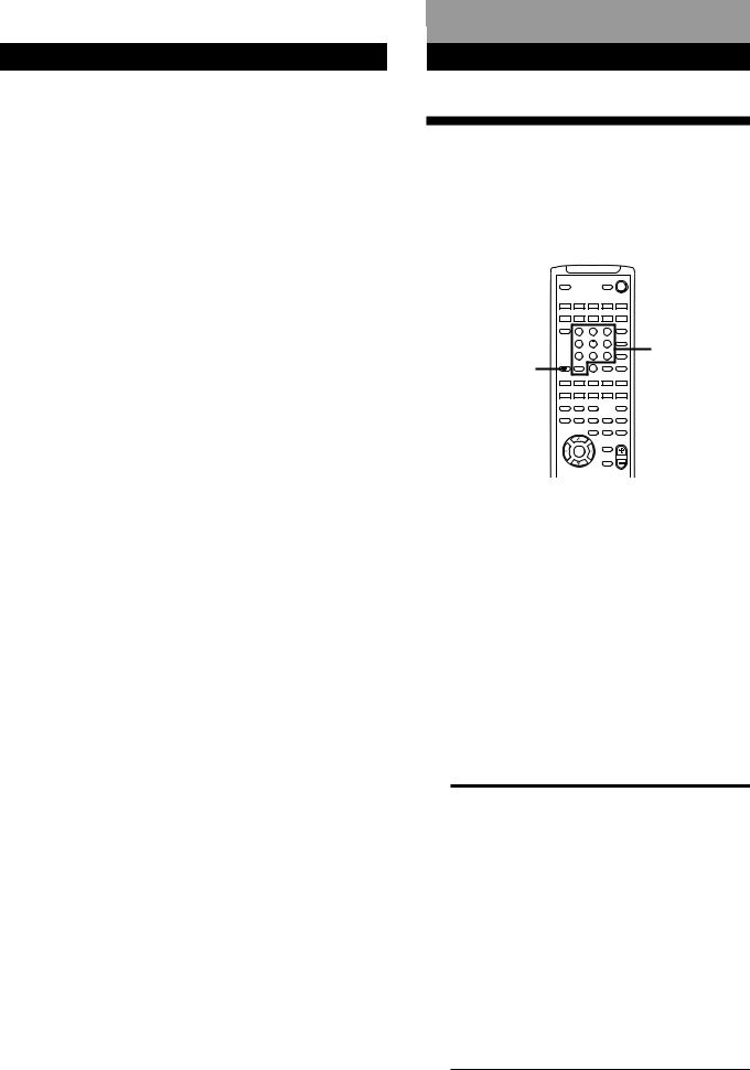
Sound Adjustment
Resetting customized sound fields to the factory settings
1If the power is on, press POWER to turn off the power.
2Hold down SOUND FIELD ON/OFF and press POWER.
“SURR CLEAR” appears in the display and all the sound fields are reset at once.
Advanced RemoteSoundOperationsAdjustment
Operating One Component While Using Another (background operation)
You can temporarily operate other components while listening to or watching a program.
|
VISUALSYSTEM OFF |
SLEEP |
POWER |
|
SYSTEM CONTROL / FUNCTION |
|
||||
|
VIDEO 1 |
VIDEO 2 |
VIDEO 3 |
LD |
TV |
|
|
|
(AUTO CATEGORIZE SYSTEM) |
|
|
||
|
TAPE |
DAT/MD |
CD |
TUNER |
PHONO |
|
|
TV |
|
|
|
5.1 |
|
|
CONTROL |
1 |
2 |
3 |
INPUT |
|
|
ON |
|
|
|||
|
|
4 |
5 |
6 |
TV/VIDEO |
|
|
|
DISC |
Numeric |
|||
|
|
|
|
|
D.TUNING |
|
|
|
7 |
8 |
9 |
+ |
buttons |
|
BACK |
>10 |
0 |
|
– |
|
BACKGROUND |
GROUND |
SHIFT |
|
ENTER |
PRESET |
|
|
|
|
RMS/START |
|
||
|
– SUB CH + |
POSITION SWAP |
ANT |
|
||
|
TV/VTR |
|
||||
|
0 ) = + D. SKIP |
|
||||
—RMS —
DIRECTION |
CLEAR |
P IN P |
JUMP |
|
9 |
( |
p |
P |
r |
— SOUND FIELD — |
|
TEST |
||
ON/OFF |
GENRE |
MODE |
|
TONE |
EQ/ |
BAND |
SLOPE |
— LEVEL — |
|
TONE |
||||
|
|
|
+ |
+ |
DIGTAL |
|
DIRECT |
REAR |
CENTER |
PROCESSING |
|
– |
– |
|
CONTROL |
|
|||
MASTER
BASS VOL
BOOST
DPC
MODE
MUTING
PROGRAMMABLE
1Hold down BACKGROUND.
2Press both the corresponding button of the component you’re going to use (see the table below) and one of the following buttons at the same time; VISUAL POWER, TV/VIDEO, CH/ PRESET +/–, ANT TV/VTR, D.SKIP, (, 9, p,
0/), =/+, P, r.
Example: To start recording on a tape deck while listening to a CD
While holding down BACKGROUND, press 4 (or 5) and press r+ (at the same time.
The following buttons correspond to the components.
The button |
Corresponds to |
|
|
1 |
CD player |
|
|
2 |
DAT deck |
|
|
3 |
MD deck |
|
|
4 |
Tape deck A |
|
|
5 |
Tape deck B |
|
|
6 |
LD player |
|
|
7 |
VCR (remote control mode VTR 1*) |
|
|
8 |
VCR (remote control mode VTR 2*) |
|
|
9 |
VCR (remote control mode VTR 3*) |
|
|
>10 |
DBS (Digital Broadcasting System) |
|
tuner |
*Sony VCRs are operated with a VTR 1, 2 or 3 setting that corresponds to Beta, 8mm, and VHS,
respectively.
19EN
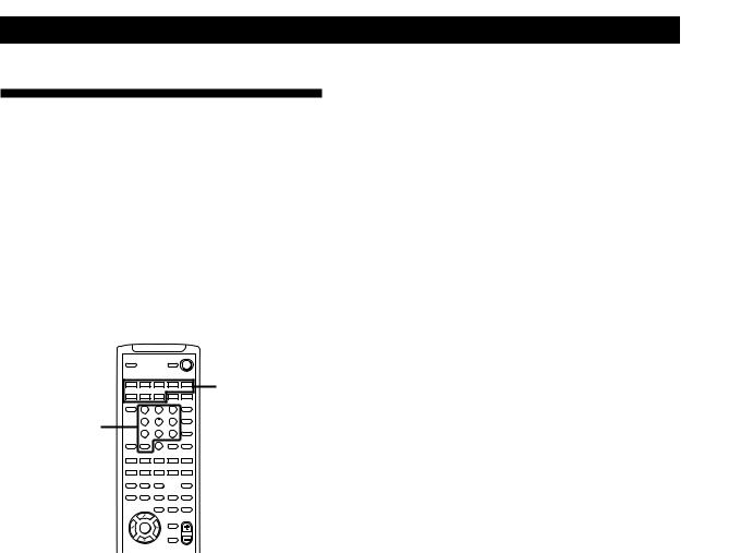
AdvanceSound djustRemoteentOperations
Changing the Factory Setting
of a FUNCTION Button
If the factory settings of the SYSTEM CONTROL/ FUNCTION buttons (page 11) don’t match your system components, you can change them. For example, if you connect a Sony LD player to the VIDEO 2 jacks, you can assign the VIDEO 2 button to set the remote to control the LD player.
Note that the settings of the TUNER and PHONO buttons cannot be changed.
|
|
|
|
VISUALSYSTEM OFF |
|
|
|
SLEEP |
|
|
POWER |
|
|
|
SYSTEM CONTROL / FUNCTION |
|
|
|||
|
VIDEO 1 |
VIDEO 2 |
VIDEO 3 |
LD |
TV |
SYSTEM |
|
|
(AUTO CATEGORIZE SYSTEM) |
|
|||
|
TAPE |
DAT/MD |
CD |
TUNER |
PHONO |
CONTROL/ |
|
CONTROL |
|
|
|
INPUT |
|
|
TV |
|
|
|
5.1 |
|
|
ON |
1 |
2 |
3 |
|
FUNCTION |
Numeric |
|
4 |
5 |
6 |
TV/VIDEO |
|
|
DISC |
|
||||
|
|
|
|
|
D.TUNING |
|
buttons |
|
7 |
8 |
9 |
+ |
|
BACK |
|
|
|
CH/ |
|
|
|
GROUND |
SHIFT |
0 |
ENTER |
PRESET |
|
|
|
>10 |
|
– |
|
|
|
|
|
|
RMS/START |
|
|
|
– SUB CH + |
POSITION SWAP |
ANT |
|
||
|
TV/VTR |
|
||||
|
0 ) = + D. SKIP |
|
||||
—RMS —
DIRECTION |
CLEAR |
P IN P |
JUMP |
|
9 |
( |
p |
P |
r |
— SOUND FIELD — |
|
TEST |
||
ON/OFF |
GENRE |
MODE |
|
TONE |
EQ/ |
BAND |
SLOPE |
— LEVEL — |
|
TONE |
||||
|
|
|
+ |
+ |
DIGTAL |
|
DIRECT |
REAR |
CENTER |
PROCESSING |
|
– |
– |
|
CONTROL |
|
|||
MASTER
BASS VOL
BOOST
DPC
MODE
MUTING
PROGRAMMABLE
1Hold down the SYSTEM CONTROL/FUNCTION button whose function you want to change (VIDEO 2, for example).
2Press the corresponding numeric button of the component you want to assign to the SYSTEM CONTROL/FUNCTION button (6 - LD player, for example).
For the numeric buttons, see the table in “Operating One Component While Using Another” on page 19.
Now you can use the VIDEO 2 button to control your Sony LD player.
To reset the setting to the factory setting
Repeat the above procedure.
20EN
|
|
|
|
Additional Information |
Additional Information |
|
|
|
Troubleshooting
If you experience any of the following difficulties while using the amplifier, use this troubleshooting guide to help you remedy the problem. Should any problem persist, consult your nearest Sony dealer.
There’s no sound or only a very low-level sound is heard.
/Check that the speakers and components are connected securely.
/Make sure you select the correct component on the amplifier.
/Make sure you set the SPEAKERS selector correctly (see page 6).
/Press MUTING on the remote if “MUTING” is shown in the display.
/The protective device on the amplifier has been activated because of a short circuit. Turn off the amplifier, eliminate the short-circuit problem and turn on the power again.
The left and right sounds are unbalanced or reversed.
/Check that the speakers and components are connected correctly and securely.
/Adjust the BALANCE control.
Severe hum or noise is heard.
/Check that the speakers and components are connected securely.
/Check that the connecting cords are away from a transformer or motor, and at least 10 feet (3 meters) away from a TV set or fluorescent light.
/Place your TV away from the audio components.
/Make sure you connect a ground wire to the ySIGNAL GND terminal.
/The plugs and jacks are dirty. Wipe them with a cloth slightly moistened with alcohol.
No sound is heard from the center speaker.
/Select a PRO LOGIC or MOVIE (except MONO MOVIE) sound field (see pages 16 and 17).
/Select the appropriate center mode (see page 15).
/Adjust the speaker volume appropriately (see page 15).
A component cannot be selected.
/Check the FUNC HOOK UP setting of the component (see page 12).
Recording cannot be made.
/Check that the components are connected correctly.
/Select the source component with the VIDEO/AUDIO FUNCTION buttons.
/You cannot record audio from a program source connected to the 5.1 INPUT jacks (see page 13).
No sound or only a very low-level sound is heard from the rear speakers.
/Select the appropriate center mode (see page 15).
/Adjust the speaker volume appropriately (see page 15).
/Make sure you turned on the sound field.
Surround effect cannot be obtained.
/Turn on the sound field.
/Make sure that the SPEAKERS selector is set to A or B when you use two sets of front speakers.
No picture or an unclear picture appears on the TV screen or on the monitor.
/Select the appropriate function on the amplifier.
/Set your TV to the appropriate input mode (press TV/ VIDEO on the remote for Sony TVs).
/Place your TV away from the audio components.
The remote does not function.
/Point the remote at the remote sensor gon the amplifier.
/Remove the obstacles in the path of the remote and the amplifier.
/Replace both batteries in the remote with new ones if they are weak.
/Make sure you select the correct function on the remote.
/Pressing TV CONTROL ON sets the remote to operate the TV only. In this case, press one of the SYSTEM CONTROL/FUNCTION buttons before operating the amplifier (etc.).
/Press POWER on the main unit to turn on the amplifier and check the FUNC HOOK UP setting of the component you want to use. If the component is set to –N–, the amplifier and the component will not turn on when you press respective SYSTEM CONTROL/ FUNCTION button.
21EN

Additional Information
Specifications
Amplifier section
POWER OUTPUT
Stereo mode (4 ohms at 1 kHz, THD 0.7%) 100 W + 100 W
Surround mode (4 ohms at 1 kHz, THD 0.7%)
Front: 100 W/ch
Center *: 100 W
Rear*: 100 W/ch
*Depending on the sound field settings and the source, sound will not be output.
5.1mode (4 ohms at 1 kHz, THD 0.7%)
Front: 100 W/ch
Center: 100 W
Rear: 100 W/ch
Harmonic distortion at rated output
Less than 0.09% (with DIRECT PASS on)
Frequency response
PHONO: RIAA equalization curve ±0.5 dB
CD, TAPE/MD, VIDEO 1, 2:
10 Hz - 50 kHz +0–1 dB (with DIRECT PASS on)
Inputs
|
|
|
S/N (weighting |
|
Sensitivity |
Impedance network, input |
|
|
|
|
level) |
PHONO |
2.5 mV |
50 kilohms |
75 dB* |
|
(A, 2.5 mV) |
||
|
|
|
|
|
|
|
|
CD |
200 mV |
50 kilohms |
82 dB* |
|
(A, 200 mV) |
||
|
|
|
|
|
|
|
|
TAPE/MD, VIDEO 1, 2, |
150 mV |
50 kilohms |
82 dB* |
3, TV/LD, TUNER |
(A, 150 mV) |
||
|
|
|
|
|
|
|
|
5.1 INPUT |
200 mV |
50 kilohms |
82 dB* |
|
(A, 150 mV) |
||
|
|
|
|
* ‘78 IHF
Outputs VIDEO 1, 2 AUDIO OUT: Voltage: 150 mV Impedance: 10 kilohms
WOOFER: Voltage: 2 V
Impedance: 1 kilohms PHONES:
Accepts low and high impedance headphones
BASS BOOST +10 dB at 70 Hz
TONE ±8 dB at 100 Hz and 10 kHz
Video section
Inputs |
1 Vp-p 75 ohms |
Outputs |
1 Vp-p 75 ohms |
General
System |
Preamplifier section: |
|
Low-noise NF type equalizer |
|
Power amplifier section: |
|
Pure-complementary SEPP |
Power requirements
230 V AC, 50/60 Hz
Power consumption
240 W
AC outlets 1 switched, maximum 100 W
Dimensions 430 × 155 × 350 mm
including projecting parts and controls
Mass (Approx.) 9.8 kg
Supplied accessories
See page 4.
Design and specifications are subject to change without notice.
22EN
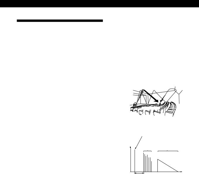
Additional Information
Glossary
Center mode
Setting of speakers to enhance Dolby Pro Logic Surround mode. To obtain the best possible surround sound, select one of the four center modes (page 15) according to your speaker system.
Delay time
Time lag between the surround sound output from front speakers and rear speakers. By adjusting the delay time of the rear speakers, you can obtain the feeling of presence. Make the delay time longer when you have placed the rear speakers in a small room or close to your listening position, and make it shorter when you have placed them in a large room or apart from your listening position.
Dolby Digital (AC-3)
This is a new digital surround system proposed to reproduce Dolby SR-D (the 3 dimensional sound system developed for use in movie theaters) in the home. This technology allows you to enjoy the full 5.1 ch soundtrack intended by the filmmaker, in the comfort of your own home.
Dolby Pro Logic Surround
Decoding system of Dolby Surround sound standardized in TV programs and movies. Compared with the former Dolby Surround system, Dolby Pro Logic Surround improves sound image by using four separate channels: off-screen audio effects, on-screen dialog, left-to-right panning, and music. These channels manipulate the sound to be heard and enhance the action as it happens on the screen. To take advantage of Dolby Pro Logic, you should have at least one pair of rear speakers and/or one center speaker. You also need to select the appropriate center mode to enjoy a full effect.
Effect level
Combination of the level of early reflections and reverberation. You can adjust the effect level in 6 levels. As you select higher levels, the room becomes “live,” and as you select lower levels, the room becomes “dead.”
5.1 INPUT jacks
These jacks are used to input decoded Dolby Digital (AC-3) audio signals, allowing you to enjoy 5.1 channel surround sound. Use these jacks to connect a Dolby Digital (AC-3) decoder or a DVD player with a built-in (AC-3) decoder.
Parameter
Variable of sound that composes sound image, such as tone or delay time. You can customize the pre-programmed sound fields by adjusting parameters to suit your listening situation.
Sound field
Sound pattern produced by a sounding source or sources in a given environment due to direct and reflected sounds and the acoustics of the environment.
Surround sound
Sound that consists of three elements: direct sound, early reflected sound (early reflections) and reverberative sound (reverberation). The acoustics where you hear the sound affect the way these three sound elements are heard. These sound elements are combined in such a way that you can actually feel the size and the type of a concert hall.
• Types of sound
Reverberation
Early reflections
 Direct sound
• Transition of sound from rear speakers
Direct sound
Level
Early
reflections Reverberation
Time
Early reflection time
23EN
Additional Information
Table of Functions of the SET UP Button
You can make various settings using the SET UP button on the main unit and the digital processing control buttons. Operations related to each menu are explained in the previous sections. The table below describes how to access each menu.
Press SET UP repeatedly to select* |
Press or to select |
Then press or to select |
See page |
CTR MODE |
PHANTOM |
— |
15 |
|
|
|
|
|
3 CH LOGIC |
|
|
|
|
|
|
|
NORMAL |
|
|
|
|
|
|
|
WIDE |
|
|
|
|
|
|
FUNC HOOK UP |
VIDEO 1 |
–Y– or –N– |
12 |
|
|
|
|
VIDEO 2
TV/LD
TAPE
DAT/MD
CD
TUNER
PHONO
* “USE CURSOR” appears in the display after 4 seconds you press the SET UP button.
24EN
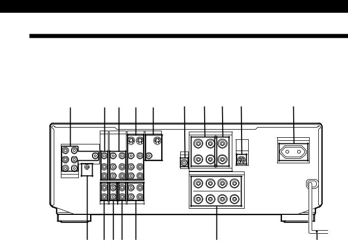
Additional Information
Rear Panel Descriptions
|
|
|
|
|
|
|
|
|
|
|
|
|
|
|
|
|
|
|
|
|
1 |
2 |
3 |
4 |
5 |
6 |
7 |
8 |
9 |
0 |
|
|
TV / LD |
VIDEO 2 |
VIDEO 1 |
MONITOR |
||
|
|
|
|
|
OUT |
IN |
OUT |
|
FRONT REAR |
|
|
|
|
|
|
|
VIDEO |
VIDEO |
VIDEO |
VIDEO |
VIDEO |
VIDEO |
VIDEO |
L |
IN |
IN |
OUT |
IN |
OUT |
IN |
OUT |
R
|
AUDIO |
AUDIO |
AUDIO |
AUDIO |
AUDIO |
|
IN |
OUT |
IN |
OUT |
IN |
|
SIGNAL |
|
|
|
L |
|
GND |
|
|
|
|
CENTER WOOFER |
y |
|
|
|
|
5.1 INPUT |
|
|
|
|
R |
|
IN |
IN |
IN |
RECOUT |
IN |
|
|
|
|
|
L |
|
|
|
|
|
R |
|
PHONO |
TUNER |
CD |
TAPE / MD |
|
!¶ !§! !¢ !£
SURROUND SPEAKERS
R |
REAR L |
CENTER |
|
|
AC OUTLET |
|
|
|
|
WIRELESS |
|
|
|
|
|
SWITCHED 100W MAX |
|
+ |
|
|
+ |
REAR |
|
|
|
SPEAKER |
|
||
|
|
|
|
|
|
WOOFER |
|
|
|
|
|
AUDIO – |
|
|
– |
|
|
OUT |
|
|
|
|
|
R |
L |
|
|
|
|
|
IMPEDANCE USE 4–16 Ω |
|
|
|
|
|
FRONT SPEAKERS |
|
|
|
|
+ |
IMPEDANCE USE 4–16 Ω |
|
+ |
|
|
|
– – |
|
|
||
A |
|
|
|
A |
|
R + |
|
– – |
|
+ L |
|
B |
|
|
|
B |
|
!™ |
!¡ |
1 5.1 INPUT |
0 AC OUTLET |
2 TV/LD |
!¡ AC power cord |
3 VIDEO 2 |
!™ FRONT SPEAKERS (A/B) |
4 VIDEO 1 |
!£ TAPE/MD |
5 MONITOR |
!¢ CD |
6 WOOFER |
! TUNER |
7 SURROUND SPEAKERS (REAR) |
!§ PHONO |
8 SURROUND SPEAKERS (CENTER) |
!¶ ySIGNAL GND |
9 WIRELESS REAR SPEAKER |
|
25EN
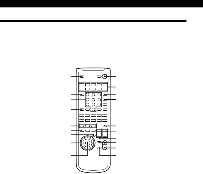
Additional Information
Remote Button Descriptions
Page numbers in parentheses refer to procedures that use the remote button. In these procedures, the remote button is either required or used in place of a main-unit button with the same function and name (or a similar name).
Refer to the table on the next page for an explanation of remote buttons not indicated below or for remote buttons without a corresponding button on the main unit.
1 |
|
|
|
VISUALSYSTEM OFF |
2 |
|
SLEEP |
|
|
POWER |
|
||
|
|
SYSTEM CONTROL / FUNCTION |
|
|||
|
VIDEO 1 |
VIDEO 2 |
VIDEO 3 |
LD |
TV |
3 |
|
|
(AUTO CATEGORIZE SYSTEM) |
|
|||
|
TAPE |
DAT/MD |
CD |
TUNER |
PHONO |
|
!ª |
TV |
1 |
2 |
3 |
5.1 |
4 |
|
CONTROL |
|
|
INPUT |
|
|
|
ON |
|
|
|
|
|
!• |
|
4 |
5 |
6 |
TV/VIDEO |
5 |
|
|
|
|
|
D.TUNING |
|
|
|
7 |
8 |
9 |
DISC |
|
|
|
+ |
|
|||
!¶ |
BACK |
|
|
|
CH/ |
|
GROUND |
SHIFT |
0 |
ENTER |
PRESET |
|
|
|
>10 |
|
– |
|
||
|
|
RMS/START |
|
|||
– SUB CH + |
ANT |
POSITION SWAP TV/VTR |
0 
 )
) 
 =
=
 +
+ 
 D. SKIP
—RMS —
|
DIRECTION |
CLEAR |
P IN P |
JUMP |
|
|
|
9 |
( |
p |
P |
r |
|
!§ |
— SOUND FIELD — |
|
TEST |
6 |
||
EQ/ |
|
MODE |
|
TONE |
||
|
ON/OFF GENRE |
|
|
|||
! |
TONE |
BAND |
SLOPE |
+ |
+ |
|
!¢ |
— LEVEL — |
7 |
||||
CONTROL |
|
|
– |
– |
||
|
DIGTAL |
|
DIRECT |
REAR |
CENTER |
|
|
PROCESSING |
|
|
|
|
|
|
|
|
|
BASS |
MASTER |
8 |
|
|
|
|
VOL |
||
!£ |
|
|
|
BOOST |
|
9 |
|
DPC |
|
|
|
||
|
|
MODE |
|
|
|
0 |
|
|
|
|
MUTING |
|
|
PROGRAMMABLE
!™ !¡
1 SLEEP (14)
2 SYSTEM OFF (11)
3SYSTEM CONTROL/ FUNCTION (9 to 14, 20)
4 5.1 INPUT (11, 13)
5 TV/VIDEO (11)
6 TEST TONE (15)
7 CENTER LEVEL +/– (15)
8 REAR LEVEL +/– (15)
9 BASS BOOST (10)
0 MASTER VOL +/– (10, 15) !¡ MUTING (10)
!™ DPC MODE (12, 18)
!£ DIGITAL PROCESSING CONTROL (12, 14, 15, 18)
!¢ DIRECT (10)
! EQ/TONE (18)
!§ SOUND FIELD ON/OFF/ GENRE/MODE (16)
!¶ BACKGROUND (19) !• Numeric buttons (19, 20) !ª TV CONTROL ON (11)
26EN

Remote |
Operates |
Function |
|
Button |
|
|
|
|
|
|
|
0-9, >10 |
Tuner |
Selects preset numbers. |
|
|
|
|
|
|
CD player/MD |
Selects track numbers. |
|
|
deck/LD player 0 selects track 10. |
|
|
|
|
|
|
|
TV/VCR |
Selects channel numbers. |
|
|
|
|
|
CH/PRESET |
Tuner |
Scans and selects preset |
|
+/– |
|
stations. |
|
|
|
|
|
|
TV/VCR |
Selects preset channels. |
|
|
|
|
|
DISC |
CD player |
Selects discs (CD player |
|
|
|
with multi-disc changer |
|
|
|
only). |
|
|
|
|
|
D.TUNING |
Tuner |
Selects the direct tuning |
|
|
|
mode. |
|
|
|
|
|
D. SKIP |
CD player |
Skips discs (CD player with |
|
|
|
multi-disc changer only). |
|
|
|
|
|
SHIFT |
Tuner |
Selects the memory bank. |
|
|
|
|
|
0/) |
CD player |
Searches tracks (forward or |
|
|
|
backward). |
|
|
|
|
|
|
Tape deck/MD |
Fast forwards or rewinds. |
|
|
deck/VCR/LD |
|
|
|
player |
|
|
|
|
|
|
=/+ |
CD player/ |
Skips tracks. |
|
|
MD deck/LD |
|
|
|
player |
|
|
|
|
|
|
P |
CD player/ |
Pauses play or record. (Also |
|
|
Tape deck/MD |
starts recording with |
|
|
deck/LD |
components in record |
|
|
player/VCR |
standby.) |
|
|
|
|
|
( |
CD player/ |
Starts play. |
|
|
Tape deck/MD |
|
|
|
deck/LD |
|
|
|
player/VCR |
|
|
|
|
|
|
p |
CD player/ |
Stops play. |
|
|
Tape deck/MD |
|
|
|
deck/LD |
|
|
|
player/VCR |
|
|
|
|
|
|
9 |
Tape deck |
Starts play on the reverse |
|
|
|
side. |
|
|
|
|
|
r |
Tape deck |
Sets tape decks to the record |
|
|
|
standby mode. |
|
|
|
|
|
r+ ( |
Tape deck/MD |
Starts recording when |
|
|
deck/VCR |
pressed with ((or 9on |
|
|
|
tape deck). |
|
|
|
|
|
Additional Information
Remote |
Operates |
Function |
Button |
|
|
|
|
|
RMS |
Tape deck |
Selects tape direction (tape |
DIRECTION |
|
decks with the RMS* |
|
|
function only). |
|
|
|
RMS CLEAR |
Tape deck |
Clears RMS* program (tape |
|
|
decks with the RMS |
|
|
function only). |
|
|
|
RMS |
Tape deck |
Programs tracks (tape deck |
DIRECTION |
|
with the RMS* function |
9/( |
|
only). |
|
|
|
ENTER |
TV/VCR/CD |
Changes channels/discs |
|
player |
when used with 0-9. |
|
|
|
VISUAL |
TV/VCR/LD |
Turns on or off the power. |
POWER |
player |
|
|
|
|
-/- - |
TV |
Selects the channel entry |
|
|
mode, either one or two |
|
|
digit (in Europe only). |
|
|
|
SUB CH +/– |
TV |
Selects preset channels for |
|
|
** |
|
|
the small picture. |
POSITION |
TV |
Changes the position of the |
|
|
small picture.** |
SWAP |
TV |
Swaps the small and the |
|
|
large picture.** |
P IN P |
TV |
Activates the picture-in- |
|
|
picture function.** |
JUMP |
TV |
Jumps back and forth |
|
|
between the previous and |
|
|
current channels. |
|
|
|
ANT TV/VTR |
VCR |
Selects output signal from |
|
|
the antenna terminal: TV |
|
|
signal or VCR program. |
|
|
|
MASTER VOL |
TV |
Normally, adjusts the |
+/– |
|
master volume of the |
|
|
amplifier. |
|
|
If TV CONTROL ON was |
|
|
pressed, it adjusts the |
|
|
volume on the TV. |
|
|
|
MUTING |
TV |
Normally, mutes the sound |
|
|
from the amplifier. |
|
|
If TV CONTROL ON was |
|
|
pressed, the sound on the |
|
|
TV itself is muted. |
|
|
|
SLOPE |
— |
Not applicable. |
|
|
|
BAND |
— |
Not applicable. |
*RMS: Random Music Sensor
**Only for Sony TVs with the picture-in-picture function
27EN

AdvancedIndex Remote Operations
A
Adjusting
delay time 18 speaker volume 15
surround sound parameters 18
tone parameter 18
B
Background operation 19 Battery 4
C
Center mode 15, 23 Connecting. See Hookups Customizing
remote 20 sound field 17, 18
D
Delay time 18, 23 Dolby Pro Logic
Surround 14-16, 23
Dolby Surround setup 14, 15 Dubbing. See Recording
E, F, G
Editing. See Recording
Effect level 17, 23
H
Hookups
AC power cord 8 audio components 5 overview 4 speakers 5, 6 TV/VCRs 7, 8
I, J, K
Indexing program source 12
L
Labeling. See Indexing program source
M, N, O
Making components selectable/unselectable 12
P, Q
Parameter 17, 18, 23
R
Recording
on an audio tape or MD 13 on a video tape 14
Remote
background operation 19 changing the setting 20
S
Selecting a component on the main unit 9 using the remote 11
Selecting the center mode 15 Sleep timer 14
Sound field
adjustable parameters 17 customizing 17, 18 pre-programmed 16, 17, 23 resetting 19
Speakers connection 5, 6 placement 6
selecting speaker system 6 Supplied accessories 4 Surround sound 14, 15, 23
T
Test tone 16
U, V
Unpacking 4
W, X, Y, Z
Watching TV/video programs 10
Names of controls
Buttons
BACKGROUND 19 BASS BOOST 9 CENTER LEVEL +/– 14 DIMMER 9
DIRECT PASS 9 DISPLAY 12
DPC MODE 12, 17 GENRE 16 MODE 9, 16 MUTING 10
REAR LEVEL +/– 14 SET UP 9, 14
SLEEP 14 SOUND FIELD
ON/OFF 16, 17
SYSTEM CONTROL/
FUNCTION 11, 20 SYSTEM OFF 11 TEST TONE 14
TV CONTROL ON 11 VIDEO/AUDIO FUNCTION 9, 12, 13
 /
/ /
/ /
/ (digital processing control) 9, 12, 14, 17
Numeric buttons 19, 20 5.1 INPUT 9, 11
Switch and selector
POWER 9, 17
SPEAKERS 6, 9
Connectors and terminals
FRONT SPEAKERS A/B 5 ySIGNAL GND 5 SURROUND SPEAKERS (CENTER/REAR) 5
Controls
BALANCE 9, 14
MASTER VOLUME 9
Jacks
CD 5 MONITOR 7 PHONES 9 PHONO 5 TAPE/MD 5 TUNER 5 TV/LD 7 VIDEO 1/2/3 7
WIRELESS REAR SPEAKER 5 WOOFER 5
5.1 INPUT 8
Indicators
BASS BOOST 10 DIRECT PASS 10 INDEX 12 STANDBY 9 SUR 18
TONE 18
5.1 INPUT 12
Other
AC OUTLET 8 g 4
28EN
|
|
|
|
|
|
|
Quick Reference Guide |
Advanced Remote Operations |
|||
|
|
|
|
|
|
|
|
|
|
|
|
|
|
|
|
|
|
Selecting a
Component
Example1: Playing a CD
Press repeatedly until
AUDIO FUNCTION
the CD indicator
lights up.
v
Turn on the CD player. v
Start playing.
Example2: Watching a video tape
Press repeatedly until
VIDEO FUNCTION
the VIDEO 1 indicator
lights up.
v
Turn on the VCR. v
Start playing.
Using Preprogrammed Sound Fields
Example: Watching a Dolby Surround-encoded movie on a laser disc player connected to TV/LD
Press repeatedly until
AUDIO FUNCTION
the TV/LD indicator
lights up.
v
SOUND FIELD
ON / OFF
v |
|
GENRE |
Press repeatedly to |
|
|
|
select PRO LOGIC. |
v
MODE Press repeatedly to select PRO LOGIC or
ENHANCED.
v
Turn on the LD player. v
Start playing.
29EN

AVERTISSEMENT
Afin d’éviter tout risque d’incendie ou d’électrocution, ne pas exposer l’appareil à la pluie ou à l’humidité.
Afin d’écarter tout risque d’électrocution, garder le coffret fermé.
Ne confier l’entretien de l’appareil qu’à un personnel qualifié.
N’installez pas l’appareil dans un espace confiné comme dans une bibliothèque ou un meuble encastré.
Précautions
Sécurité
•Si un solide ou un liquide pénètre dans le coffret, débranchez l’amplificateur et faites-le vérifier par un technicien qualifié avant de le remettre en service.
Sources d’alimentation
•Avant de mettre l’amplificateur en service, vérifiez que sa tension de fonctionnement correspond à celle du courant secteur local. La tension de fonctionnement est indiquée sur la plaque signalétique à l’arrière de l’amplificateur.
•L’amplificateur n’est pas déconnecté de la source d’alimentation tant qu’il est branché sur une prise murale, même si vous le mettez hors tension.
•Si vous ne comptez pas utiliser l’amplificateur pendant un certain temps, débranchez-le de la prise murale. Pour débrancher le cordon, tirez sur la fiche. Ne jamais tirer sur le cordon proprement dit.
•Par mesure de sécurité, une lame de la fiche est plus large que l’autre et vous ne pouvez l’insérer que dans un sens. Si vous avez du mal à enfoncer complètement la fiche dans la prise, contactez votre revendeur.
•Si le cordon d’alimentation secteur doit être remplacé, adressez-vous à un technicien qualifié uniquement.
Installation
•Installez l’amplificateur dans un endroit bien ventilé pour éviter tout risque de surchauffe interne et prolonger la durée de vie des composants.
•N’installez pas l’amplificateur près d’une source de chaleur, dans un endroit en plein soleil, poussiéreux ou exposé à des chocs mécaniques.
•Ne posez rien sur le coffret qui puisse bloquer les orifices de ventilation et provoquer un mauvais fonctionnement.
Fonctionnement
•Avant de raccorder d’autres appareils, mettez l’amplificateur hors tension et débranchez-le.
Nettoyage
•Nettoyez le coffret, le panneau et les commandes avec un chiffon doux légèrement imprégné d’une solution détergente douce. N’utilisez pas de tampon abrasif, poudre à récurer ou solvant, comme de l’alcool ou de la benzine.
Pour toute question ou tout problème concernant l’amplificateur, consultez votre revendeur Sony.
2F
 Loading...