


4-249-347-15(3)
Multi-Channel
Integrated Amplifier
Operating Instructions
TA-DA9000ES
©2003 Sony Corporation

WARNING
To prevent fire or shock hazard, do not expose the unit to rain or moisture.
To prevent fire, do not cover the ventilation of the apparatus with news papers, table-cloths, curtains, etc. And don’t place lighted candles on the apparatus.
To prevent fire or shock hazard, do not place objects filled with liquids, such as vases, on the apparatus.
Do not install the appliance in a confined space, such as a bookcase or built-in cabinet.
Don’t throw away batteries with general house waste; dispose of them correctly as chemical waste.
About This Manual
•The instructions in this manual are for model TADA9000ES. Check your model number by looking at the lower right corner of the front panel. In this manual, TA-DA9000ES (area code CEL) is used for illustration purposes unless stated otherwise. Any difference in operation is clearly indicated in the text, for example, “Model of area code CEL only”.
•The instructions in this manual describe the controls on the amplifier. You can also use the controls on the supplied remote if they have the same or similar names as those on the amplifier. For details on the use of your remote, see the separate operating instructions supplied with the remote.
About area codes
The area code of the amplifier you purchased is shown on the upper right portion of the rear panel (see the illustration below).
SPEAKERS |
AC IN |
4-XXX-XXX-XX AA |
B |
B |
Area code |
A |
A |
|
|
AC OUTLET |
|
B 
 B
B
A 
 A
A
Any differences in operation, according to the area code, are clearly indicated in the text, for example, “Models of area code AA only”.
This amplifier incorporates Dolby* Digital and Pro Logic Surround and the DTS** Digital Surround System.
*Manufactured under license from Dolby Laboratories.
“Dolby”, “Pro Logic” and the double-D symbol are trademarks of Dolby Laboratories.
**“DTS”, “DTS-ES Extended Surround”, and “Neo:6” are trademarks of Digital Theater Systems, Inc.
2GB

Table of Contents |
|
Getting Started |
|
1: Check how to hookup your |
|
components ....................................... |
4 |
1a: Connecting components with |
|
digital audio output jacks ........... |
6 |
1b: Connecting components with |
|
multi channel output jacks.......... |
9 |
1c: Connecting components with only |
|
analog audio jacks .................... |
11 |
2: Connecting speakers ......................... |
13 |
3: Connecting the AC power cord ........ |
17 |
4: Setting up the speakers ..................... |
18 |
5: Adjusting the speaker levels and |
|
balance ............................................ |
21 |
— TEST TONE |
|
Amplifier Operation |
|
Selecting the component ....................... |
22 |
Listening to multi channel sound .......... |
23 |
— MULTI CH IN |
|
Changing the display............................. |
23 |
About the indications in the display...... |
24 |
Enjoying Surround Sound |
|
Using only the front speakers ............... |
26 |
Enjoying higher fidelity sound.............. |
26 |
— AUTO FORMAT DIRECT |
|
Selecting a sound field .......................... |
27 |
Selecting the surround back decoding |
|
mode ............................................... |
29 |
— SURR BACK DECODING |
|
Advanced Adjustments and |
|
Settings |
|
Assigning the audio input ..................... |
31 |
— DIGITAL ASSIGN |
|
Switching the audio input mode for digital |
|
components ..................................... |
32 |
— INPUT MODE |
|
Customizing sound fields...................... |
32 |
Adjusting the equalizer ......................... |
34 |
Advanced settings ................................. |
36 |
Storing the adjusted settings ................. |
42 |
— USER PRESET |
|
Other Operations |
|
Naming inputs....................................... |
44 |
Using the Sleep Timer .......................... |
44 |
Selecting the speaker system ................ |
45 |
Recording.............................................. |
46 |
CONTROL A1II Control System ........ |
48 |
i.LINK connection ................................ |
49 |
Additional Information |
|
Precautions............................................ |
50 |
Troubleshooting.................................... |
51 |
Specifications........................................ |
53 |
List of button locations and reference |
|
pages............................................... |
56 |
Index ..................................................... |
58 |
3GB

Getting Started
1: Check how to hookup your components
Steps 1a through 1c beginning on page 6 describe how to hook up your components to this amplifier. Before you begin, refer to “Connectable components” below for the pages which describe how to connect each component.
Connectable components
Component to be connected |
Page |
DVD player |
|
|
|
With digital audio outputa) |
6–7 |
With multi-channel audio outputb) |
9–10 |
With analog audio output onlyc) |
6–7 |
LD player |
|
|
|
With digital audio outputa) |
6 |
With analog audio outputc) |
6 |
TV monitor |
|
|
|
With component video inputd) |
7 or 10 |
With S-Video or composite video input only |
12 |
|
|
Satellite tuner |
|
|
|
With digital audio outputa) |
6–7 |
With analog audio output onlyc) |
6–7 |
VCR |
|
|
|
With digital audio outputa) |
6 |
With analog audio outputc) |
6 |
CD/Super Audio CD player |
|
|
|
With digital audio outputa) |
8 |
With multi-channel audio outputb) |
9 |
With analog audio output onlyc) |
11 |
MD/DAT deck |
|
|
|
With digital audio outputa) |
8 |
With analog audio output onlyc) |
11 |
Tape deck, Analog disc turntable, tuner |
11 |
|
|
Multi-channel decoder |
9 |
|
|
Video camera, video game, etc. |
12 |
|
|
a)Model with a DIGITAL OPTICAL OUTPUT or DIGITAL COAXIAL OUTPUT jack, etc.
b)Model with MULTI CH OUTPUT jacks, etc. This connection is used to output the audio decoded by the component’s internal multi-channel decoder through this amplifier.
c)Model equipped only with AUDIO OUT L/R jacks, etc.
d)Model with component video (Y, PB/CB/B-Y, PR/CR/R-Y) input jacks.
4GB
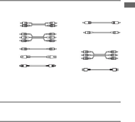
Required cords
The hookup diagrams on the subsequent pages assume the use of the following optional connection cords (A to I) (not supplied).
A Audio cord |
F Coaxial digital cord |
|
White (L) |
|
|
Red (R) |
G Monaural audio cord |
|
B Audio/video cord |
||
Black |
||
Yellow (video) |
||
Tip |
||
White (L/audio) |
||
Red (R/audio) |
Audio cord A can be torn into two monaural audio |
|
C Video cord |
cords G. |
|
|
||
Yellow |
H Component video cord |
|
D S-video cord |
Green |
|
|
Blue |
|
|
Red |
|
E Optical digital cord |
I i.LINK cable |
|
|
Notes
•Turn off the power to all components before making any connections.
•Be sure to make connections firmly to avoid hum and noise.
•When connecting an audio/video cord, be sure to match the color-coded pins to the appropriate jacks on the components: yellow (video) to yellow; white (left, audio) to white; and red (right, audio) to red.
•When connecting optical digital cords, insert the cord plugs straight in until they click into place.
•Do not bend or tie optical digital cords.
If you have Sony components with CONTROL A1II/CONTROL S jacks
See “CONTROL A1II Control System” on page 48.
If you have Sony component (SCD-XA9000ES) with i.LINK jacks
Use the i.LINK cable (I) supplied with SCD-XA9000ES. For details, refer to the Operating Instructions supplied with SCD-XA9000ES.
See also “i.LINK connection” on page 49.
Started Getting
5GB
.
1a: Connecting components with digital audio output jacks
Hooking up a DVD player, LD player, VCR, TV monitor, or satellite tuner
For details on the required cords (A–I), see page 5.
1 Connect the audio jacks.
|
|
|
VCR |
|
|
|
|
|
|
|
|
|
|
|
LD player |
|
|
|
|
|
|
|
OUTPUT INPUT |
|
|
|
|
|
|
|
|
|
OUTPUT |
|
|
|
|
|
|
|
|
|
|
|
|
|
|
|
|
AUDIO |
|
||
|
|
|
|
|
LINE |
LINE |
|
|
|
|
|
|
|
|
|
|
|
|
OUTPUT |
|
|
|
|
|
|
|
|
|
|
|
OUT |
|
|||
OUTPUT |
|
|
|
|
|
|
|
|
|
OUTPUT |
|
|
OUTPUT |
|
|||
DIGITAL |
|
|
|
|
L |
|
|
|
|
|
|
L |
|||||
DIGITAL |
OPTICAL |
|
|
|
|
|
|
|
|
|
DIGITAL |
|
|
DIGITAL |
|
||
COAXIAL |
OUT |
IN |
|
|
|
|
|
|
|
|
|
OPTICAL |
|
|
COAXIAL |
|
|
|
|
|
|
|
|
|
R |
|
|
|
|
|
|
|
|
|
R |
F* |
E* |
|
E |
|
A A |
|
|
|
|
|
E* |
F* |
A |
||||
|
IN l |
|
l OUT |
|
IN l |
|
l OUT |
|
|
|
|
|
|
|
|
|
|
|
DIGITAL |
AUDIO |
|
VIDEO |
|
|
|
|
|
COMPONENT |
|
|
|||||
|
|
|
|
DVD |
|
VIDEO |
VIDEO 1 |
|
|
||||||||
|
OPTICAL |
|
R |
L |
|
R AUDIO |
L |
VIDEO |
S2 VIDEO |
Y |
Y |
|
|
||||
|
|
|
|
|
|
|
|
|
IN |
|
|
IN |
|
|
|||
|
VIDEO 1 |
|
OUT |
|
OUT |
|
|
OUT |
OUT |
|
|
|
|
|
|
|
|
|
OUT |
|
|
|
|
|
|
|
|
|
|
|
|
||||
|
|
|
TAPE |
|
VIDEO 1 |
|
|
VIDEO 1 |
|
|
PB/CB/B-Y |
PB/CB/B-Y |
|
|
|||
|
VIDEO 1 |
|
IN |
|
IN |
|
|
IN |
IN |
|
|
|
|
|
|
|
|
|
IN |
|
|
|
|
|
|
|
|
|
|
|
|
||||
|
|
|
|
|
|
|
|
|
|
|
PR/CR/R-Y |
PR/CR/R-Y |
|
|
|||
|
LD |
|
OUT |
|
OUT |
|
|
OUT |
OUT |
|
|
|
|
|
|
|
|
|
IN |
|
|
|
|
|
|
|
|
|
|
|
|
||||
|
|
|
MD/DAT |
|
VIDEO 2 |
|
|
VIDEO 2 |
|
TV/ |
|
Y Y |
|
MONI |
|
|
|
|
|
|
|
|
|
|
|
|
|
|
|
|
|
||||
|
DVD |
|
IN |
|
IN |
|
|
IN |
IN |
SAT |
|
|
|
TOR |
|
|
|
|
IN |
|
|
|
|
IN |
|
|
|
|
OUT |
|
|
||||
|
|
|
|
|
|
|
|
|
|
|
|
|
|
|
|
|
|
|
|
|
|
|
|
|
|
|
|
|
PB/CB/B-Y |
PB/CB/B-Y |
|
|
|
||
|
TV/SAT |
|
CD/ |
|
|
|
|
|
|
|
|
|
|
|
|
|
|
|
IN |
|
SACD |
|
OUT |
|
|
OUT |
OUT |
|
|
|
|
|
|
|
|
|
|
|
IN |
|
|
|
|
|
|
|
|
|
|
|
|
|
|
|
|
|
1 |
|
VIDEO 3 |
|
|
VIDEO 3 |
|
|
PR/CR/R-Y |
PR/CR/R-Y |
|
|
|
||
|
MD/DAT |
|
|
IN |
|
|
IN |
IN |
|
|
|
|
|
|
|
|
|
|
OUT |
|
FRONT |
|
|
|
|
|
|
|
|
|
|
|
|||
|
|
|
|
|
|
|
|
|
|
|
|
|
|
|
|
||
|
|
|
|
|
VIDEO |
|
|
VIDEO |
|
FRONT |
|
|
|
|
|
|
|
|
MD/DAT |
|
SURR |
|
4 |
|
|
4 |
IN |
|
|
|
|
|
|
|
|
|
IN |
|
OUND |
|
IN |
|
|
IN |
|
|
|
|
|
|
|
|
|
|
CONTROL A1II |
LD |
LD |
SURROUND |
|
CD/SACD |
SURR |
|
|||
IN |
IN |
IN |
|||
IN |
BACK |
|
COAXIAL |
|
CENTER |
DVD |
DVD |
|
SURR BACK |
|
|
VIDEO 1 |
|
|
IN |
IN |
IN |
|
|
|
IN |
|
SUB |
|
|
|||
|
|
|
WOOFER |
|
|
|
|
|
|
|
|
2 |
TV/ |
TV/ |
|
SUB WOOFER |
CENTER |
|
LD |
|
|
|
|
|||
|
|
|
SAT |
SAT |
IN |
|
|
|
|
IN |
|
FRONT |
IN |
IN |
|
|
|
|
|
AUDIO IN |
|
PHONO |
|
|
PRE OUT |
|
|
DVD |
i.LINK S200 |
SURR |
|
|
|||
|
IN |
|
IN |
MONITOR OUT |
|
|
||
|
|
|
OUND |
|
|
|
||
|
|
|
|
TUNER |
VIDEO |
S2 VIDEO |
|
|
|
|
|
|
OUT 1 |
OUT 1 |
|
|
|
|
TV/SAT |
|
SURR |
|
|
|
||
|
|
IN |
|
|
|
|
||
|
IN |
|
BACK |
|
|
|
|
|
|
|
|
|
|
|
|
||
|
|
|
CENTER |
R |
L |
|
|
|
|
|
|
AUDIO |
OUT 2 |
|
|
|
|
|
CD/SACD |
|
|
OUT 2 |
|
|
||
|
|
|
|
|
|
|
|
|
|
IN |
|
SUB |
|
|
|
|
|
|
|
RS232C |
WOOFER |
|
|
|
|
|
|
|
MULTI CHANNEL IN |
SIGNAL |
|
|
|
|
|
|
|
|
|
|
|
|
||
|
|
|
|
GND |
|
|
|
|
E* |
F* |
|
A |
|
F* |
E* |
A |
|
OUTPUT |
OUTPUT |
|
OUTPUT |
|
OUTPUT |
OUTPUT |
OUTPUT |
|
DIGITAL |
DIGITAL |
|
AUDIO |
|
DIGITAL |
DIGITAL |
AUDIO |
|
OPTICAL |
COAXIAL |
|
OUT |
|
COAXIAL |
OPTICAL |
OUT |
|
|
|
|
|
L |
|
|
L |
|
DVD player** |
R |
R |
Satellite tuner
*Connect to either the DVD COAXIAL IN or the DVD OPTICAL IN jack. We recommend making connections to the DVD COAXIAL IN jack.
**To output the multi channel digital audio, set the digital audio output setting on the DVD player.
6GB

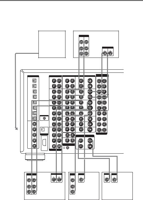
2 Connect the video jacks.
The following illustration shows how to connect a TV or satellite tuner and a DVD player with COMPONENT VIDEO (Y, PB/CB/B-Y, PR/CR/R-Y) output jacks. Connecting a TV with component video input jacks allows you to enjoy higher quality video. You can upconvert the video signals, and adjust the hue, etc. of the converted signals (page 38).
Notes
•You can listen to the sound of your TV by connecting your TV’s audio output jacks to the TV/SAT AUDIO IN jacks on the amplifier. In this case, do not connect the TV’s video output jack to the TV/SAT VIDEO IN jack on the amplifier.
•On this amplifier, standard video signals can be converted to component video and S-video signals, in addition S- video signals can be converted to component video signals. However, you cannot convert component video signals downward to standard video or S-video signals.
•When standard video signals (composite video signals) or S-video signals from a VCR etc. are converted upward on this receiver and then output to your TV, depending on the status of the video signal output, the image on the TV screen may appear distorted horizontally or no image may be output.
|
|
|
|
VCR |
|
|
|
|
|
|
|
TV monitor |
|
|
|
OUTPUT |
INPUT |
|
OUTPUT |
INPUT |
|
OUTPUT |
|
|
|
INPUT |
INPUT |
INPUT |
|
|
VIDEO |
VIDEO |
|
S VIDEO S VIDEO |
R-Y |
COMPONENT |
Y |
|
R-Y |
COMPONENT |
S VIDEO |
VIDEO |
||
|
|
|
|
|
|
B-Y |
|
|
B-Y |
Y |
|
|||
|
C |
C |
|
D |
D |
|
|
H |
|
|
H |
D |
C |
|
|
IN l |
l OUT |
|
IN l |
l OUT |
|
|
|
|
|
|
|
|
|
DIGITAL |
AUDIO |
|
VIDEO |
|
|
|
|
COMPONENT |
|
|
|
|||
|
|
|
DVD |
|
VIDEO |
VIDEO 1 |
|
|
|
|||||
OPTICAL |
R |
L |
R |
AUDIO L |
VIDEO |
S2 VIDEO |
Y |
Y |
|
|
|
|||
|
|
|
|
|
|
IN |
|
IN |
|
|
|
|||
VIDEO 1 |
OUT |
OUT |
|
OUT |
OUT |
|
|
|
|
|
|
|
|
|
OUT |
|
|
|
|
|
|
|
|
|
|
||||
|
TAPE |
VIDEO 1 |
|
VIDEO 1 |
|
|
PB/CB/B-Y |
PB/CB/B-Y |
|
|
|
|||
VIDEO 1 |
IN |
IN |
|
IN |
IN |
|
|
|
|
|
|
|
|
|
IN |
|
|
|
|
|
|
|
|
|
|
||||
|
|
|
|
|
|
|
PR/CR/R-Y |
PR/CR/R-Y |
|
|
|
|||
LD |
OUT |
OUT |
|
OUT |
OUT |
|
|
|
|
|
|
|
|
|
IN |
|
|
|
|
|
|
|
|
|
|
||||
|
MD/DAT |
VIDEO 2 |
|
VIDEO 2 |
|
|
TV/ |
|
Y Y |
|
MONI |
|
|
|
DVD |
|
|
|
|
|
|
|
|
|
|
|
|||
|
|
|
|
|
|
SAT |
|
|
|
TOR |
|
|
|
|
IN |
IN |
IN |
|
IN |
IN |
|
IN |
|
|
|
OUT |
|
|
|
|
|
|
|
|
|
|
|
|
|
|||||
|
|
|
|
|
|
|
PB/CB/B-Y |
PB/CB/B-Y |
|
|
|
|
||
TV/SAT |
CD/ |
|
|
|
|
|
|
|
|
|
|
|
|
|
IN |
SACD |
OUT |
|
OUT |
OUT |
|
|
|
|
|
|
|
|
|
|
IN |
|
|
|
|
|
|
|
|
|
DVI-D |
|
|
|
|
|
VIDEO 3 |
|
VIDEO 3 |
|
|
PR/CR/R-Y |
PR/CR/R-Y |
|
|
|
|||
|
1 |
|
|
|
|
|
|
|
||||||
MD/DAT |
IN |
|
IN |
IN |
|
|
|
|
|
|
|
|
|
|
OUT |
FRONT |
|
|
|
|
|
|
|
|
|
|
|||
|
|
|
|
|
|
|
|
|
|
|
|
|
||
MD/DAT |
|
VIDEO |
|
VIDEO |
|
|
FRONT |
|
|
|
|
|
|
|
SURR |
4 |
|
4 |
|
|
|
|
|
|
|
|
|
|
|
IN |
OUND |
IN |
|
IN |
IN |
|
|
|
|
|
|
|
|
|
|
|
|
CONTROL A1II |
|
LD |
LD |
|
SURROUND |
|
|
|
|
CD/SACD |
|
|
SURR |
IN |
IN |
IN |
|
|
|
|
|
IN |
|
|
BACK |
|
|
|
|
|||
|
COAXIAL |
|
|
CENTER |
DVD |
DVD |
|
SURR BACK |
|
|
|
|
VIDEO 1 |
|
|
|
IN |
IN |
IN |
|
|
|
|
|
IN |
|
|
SUB |
|
|
|
|
|||
|
|
|
|
WOOFER |
|
|
|
|
|
|
|
|
|
|
|
2 |
TV/ |
TV/ |
|
SUB WOOFER |
CENTER |
|
|
|
LD |
|
|
|
|
|
|
||||
|
|
|
|
SAT |
SAT |
|
|
|
|
|
|
|
IN |
|
|
FRONT |
IN |
IN |
IN |
|
|
|
|
|
|
|
AUDIO IN |
|
PHONO |
|
|
PRE OUT |
|
|
|
|
DVD |
|
i.LINK S200 |
SURR |
|
|
|
|
|||
|
IN |
|
|
IN |
MONITOR OUT |
|
|
|
|
||
|
|
|
|
OUND |
|
|
|
|
|
||
|
|
|
|
|
TUNER |
VIDEO |
S2 VIDEO |
|
|
|
|
|
|
|
|
|
OUT 1 |
OUT 1 |
|
|
|
|
|
|
TV/SAT |
|
|
SURR |
|
|
|
|
|
||
|
|
|
IN |
|
|
|
|
|
|
||
|
IN |
|
|
BACK |
|
|
|
|
|
|
|
|
|
|
|
|
|
|
|
|
|
||
|
|
|
|
CENTER |
R |
L |
|
|
|
|
|
|
|
|
|
AUDIO |
OUT 2 |
|
|
|
|
|
|
|
CD/SACD |
|
|
|
OUT 2 |
|
|
|
|
||
|
|
|
|
|
|
|
|
|
|
|
|
|
IN |
|
|
SUB |
|
|
|
|
|
|
|
|
|
|
RS232C |
WOOFER |
|
|
|
|
|
|
|
|
|
|
MULTI CHANNEL IN |
SIGNAL |
|
|
|
|
|
|
|
|
|
|
|
|
GND |
|
|
|
|
|
|
|
|
H |
|
C |
D |
C |
D |
|
H |
|
|
|
OUTPUT |
|
|
OUTPUT |
OUTPUT |
OUTPUT |
OUTPUT |
|
|
OUTPUT |
|
|
COMPONENT |
|
|
VIDEO |
S VIDEO |
VIDEO |
S VIDEO |
|
|
COMPONENT |
|
R-Y |
B-Y |
Y |
|
|
|
|
|
|
R-Y |
B-Y |
Y |
DVD player |
Satellite tuner |
continued
Started Getting
7GB
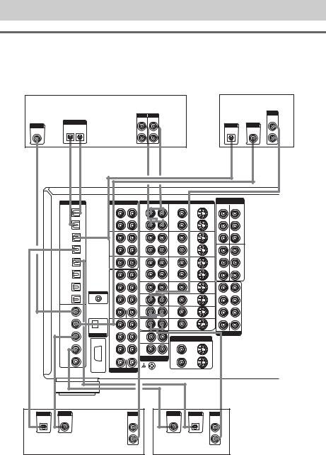
Hooking up a CD/Super Audio CD player or MD/DAT deck
For details on the required cords (A–I), see page 5.
CD/Super Audio |
MD/DAT deck |
|
CD player |
|
|
OUTPUT |
|
INPUT OUTPUT |
AUDIO |
|
|
|
LINE LINE |
|
OUT |
|
|
L OUTPUT |
OUTPUT |
DIGITAL |
L |
||
DIGITAL |
DIGITAL |
OPTICAL |
COAXIAL |
OPTICAL |
IN OUT |
|
R |
|
|
|
|
|
|
|
|
|
R |
|
A |
F* |
E* |
|
E |
|
E |
|
|
A |
A |
||
|
|
|
|
OUT |
l |
|
l IN |
OUT |
l |
l |
IN |
|
|
DIGITAL |
|
|
AUDIO |
|
VIDEO |
|
|
|
|||
|
OPTICAL |
|
|
|
R |
L |
R |
AUDIO |
L |
VIDEO |
|
S2 VIDEO |
|
VIDEO 1 |
|
|
OUT |
|
|
OUT |
|
|
OUT |
OUT |
|
|
OUT |
|
|
|
|
|
|
|
||||
|
|
|
|
TAPE |
|
|
VIDEO 1 |
|
|
VIDEO 1 |
|
|
|
VIDEO 1 |
|
|
IN |
|
|
IN |
|
|
IN |
IN |
|
|
IN |
|
|
|
|
|
|
|
||||
|
LD |
|
|
OUT |
|
|
OUT |
|
|
OUT |
OUT |
|
|
IN |
|
|
|
|
|
|
|
||||
|
|
|
|
MD/DAT |
|
|
VIDEO 2 |
|
|
VIDEO 2 |
|
|
|
DVD |
|
|
IN |
|
|
IN |
|
|
IN |
IN |
|
|
IN |
|
|
|
|
|
|
|
||||
|
|
|
|
|
|
|
|
|
|
|
|
|
|
TV/SAT |
|
|
CD/ |
|
|
|
|
|
|
|
|
|
IN |
|
|
SACD |
|
|
OUT |
|
|
OUT |
OUT |
|
|
|
|
|
IN |
|
|
|
|
|
|
|
|
|
|
|
|
1 |
|
|
VIDEO 3 |
|
|
VIDEO 3 |
|
|
|
MD/DAT |
|
|
|
|
IN |
|
|
IN |
IN |
|
|
|
OUT |
|
|
FRONT |
|
|
|
|
|
|||
|
|
|
|
|
|
|
|
|
|
|
||
|
|
|
|
|
|
|
VIDEO |
|
|
VIDEO |
|
|
|
MD/DAT |
|
|
SURR |
|
|
4 |
|
|
4 |
IN |
|
|
IN |
|
|
OUND |
|
|
IN |
|
|
IN |
|
|
|
|
|
CONTROL A1II |
|
|
|
LD |
|
|
LD |
|
|
|
CD/SACD |
|
|
SURR |
|
|
|
|
|
|
||
|
|
|
|
|
IN |
|
|
IN |
IN |
|
||
|
IN |
|
|
BACK |
|
|
|
|
|
|||
|
COAXIAL |
|
|
|
|
CENTER |
DVD |
|
|
DVD |
|
|
|
|
|
|
|
|
|
|
|
|
|||
|
VIDEO 1 |
|
|
|
|
|
IN |
|
|
IN |
IN |
|
|
IN |
|
|
SUB |
|
|
|
|
|
|||
|
|
|
|
|
|
|
|
|
|
|
||
|
|
|
|
WOOFER |
|
|
|
|
|
|
|
|
|
LD |
|
|
2 |
|
|
TV/ |
|
|
TV/ |
|
|
|
|
|
|
|
|
SAT |
|
|
SAT |
IN |
|
|
|
IN |
|
|
FRONT |
|
|
IN |
|
|
IN |
|
|
|
|
|
AUDIO IN |
|
|
|
PHONO |
|
|
|
|
|
|
DVD |
|
i.LINK S200 |
|
|
|
|
|
|
|
|
|
|
|
SURR |
|
|
IN |
|
|
|
|
|
||
|
IN |
|
|
|
|
|
|
MONITOR OUT |
||||
|
|
|
|
OUND |
|
|
|
|
|
|||
|
|
|
|
|
|
|
TUNER |
|
|
VIDEO |
|
S2 VIDEO |
|
|
|
|
|
|
|
|
|
OUT 1 |
OUT 1 |
|
|
|
TV/SAT |
|
|
SURR |
|
|
|
|
|
|
||
|
|
|
|
|
IN |
|
|
|
|
|
||
|
IN |
|
|
BACK |
|
|
|
|
|
|
|
|
|
|
|
|
|
|
|
|
|
|
|
||
|
|
|
|
|
|
CENTER |
|
R |
L |
|
|
|
|
|
|
|
|
|
AUDIO |
|
OUT 2 |
|
|
||
|
CD/SACD |
|
|
|
|
|
|
OUT 2 |
|
|||
|
IN |
|
|
SUB |
|
|
|
|
|
|
|
|
|
|
|
RS232C |
WOOFER |
|
|
|
|
|
|
|
|
|
|
|
MULTI CHANNEL IN |
SIGNAL |
|
|
|
|
|
|||
|
|
|
|
|
|
|
|
|
||||
|
|
|
|
|
|
|
GND |
|
|
|
|
|
COMPONENT
VIDEO
DVD |
Y |
Y |
VIDEO 1 |
IN |
IN |
||
PB/CB/B-Y |
PB/CB/B-Y |
||
PR/CR/R-Y PR/CR/R-Y |
|||
TV/ |
|
Y Y |
MONI |
SAT |
|
|
TOR |
IN |
|
|
OUT |
PB/CB/B-Y PB/CB/B-Y
PR/CR/R-Y PR/CR/R-Y
FRONT
SURROUND
SURR BACK
SUB WOOFER |
CENTER |
PRE OUT
*Connect to either the CD/SACD COAXIAL IN or the CD/SACD OPTICAL IN jack. We recommend making connections to the CD/SACD COAXIAL IN jack.
If you want to connect several digital components, but cannot find an unused input
See “Assigning the audio input” (page 31).
Tip
All the digital audio jacks are compatible with 32 kHz, 44.1 kHz, 48 kHz and 96 kHz sampling frequencies.
Notes
•No sound is output when playing a Super Audio CD disc on a Super Audio CD player connected to the CD/SACD OPTICAL or CD/SACD COAXIAL IN jack on this amplifier. Connect the player to the analog input jacks (CD/ SACD IN jacks). Refer to the operating instructions supplied with the Super Audio CD player.
•You cannot make digital recordings of digital multi channel surround signals.
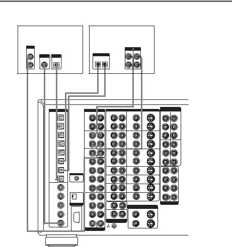
8GB
1b: Connecting components with multi channel output jacks
1 Connect the audio jacks.
If your DVD or Super Audio CD player is equipped with multi channel output jacks, you can connect it to this amplifier’s MULTI CHANNEL INPUT jacks to enjoy the multi channel sound. Alternatively, the multi channel input jacks can be used to connect an external multi channel decoder.
For details on the required cords (A–I), see page 5.
MULTI CHANNEL OUT |
DVD player, |
|
|
FRONT |
Super Audio CD |
|
|
SURR |
player, |
OUND |
Multi channel |
|
|
SURR |
decoder, etc. |
BACK |
|
CENTER |
|
SUB |
|
WOOFER |
|
MULTI CHANNEL IN 1 |
|
G G A A A |
|
|
|
|
|
|
|
||||
|
|
|
|
|
MULTI CHANNEL IN 2 |
||||||||
DIGITAL |
|
AUDIO |
|
VIDEO |
|
|
|
|
|
COMPONENT |
|||
|
|
|
|
DVD |
|
VIDEO |
VIDEO 1 |
||||||
OPTICAL |
|
R |
L |
R |
AUDIO L |
VIDEO |
S2 VIDEO |
Y |
Y |
||||
|
|
|
|
|
|
|
IN |
|
|
IN |
|||
VIDEO 1 |
|
OUT |
|
OUT |
|
OUT |
OUT |
|
|
|
|
|
|
OUT |
|
|
|
|
|
|
|
|
|
||||
|
|
TAPE |
|
VIDEO 1 |
|
VIDEO 1 |
|
|
PB/CB/B-Y |
PB/CB/B-Y |
|||
VIDEO 1 |
|
IN |
|
IN |
|
IN |
IN |
|
|
|
|
|
|
IN |
|
|
|
|
|
|
|
|
|
||||
|
|
|
|
|
|
|
|
|
PR/CR/R-Y |
PR/CR/R-Y |
|||
LD |
|
OUT |
|
OUT |
|
OUT |
OUT |
|
|
|
|
|
|
IN |
|
|
|
|
|
|
|
|
|
||||
|
|
MD/DAT |
|
VIDEO 2 |
|
VIDEO 2 |
|
TV/ |
|
Y Y |
|
MONI |
|
|
|
|
|
|
|
|
|
|
|
||||
DVD |
|
|
|
|
|
|
|
SAT |
|
|
|
TOR |
|
|
IN |
|
IN |
|
IN |
IN |
IN |
|
|
|
|
OUT |
|
IN |
|
|
|
|
|
|
|
||||||
|
|
|
|
|
|
|
|
|
PB/CB/B-Y |
PB/CB/B-Y |
|
||
TV/SAT |
|
CD/ |
|
|
|
|
|
|
|
|
|
|
|
IN |
|
SACD |
|
OUT |
|
OUT |
OUT |
|
|
|
|
|
|
|
|
IN |
|
|
|
|
|
|
|
|
|
|
|
|
|
1 |
|
VIDEO 3 |
|
VIDEO 3 |
|
|
PR/CR/R-Y |
PR/CR/R-Y |
|
||
MD/DAT |
|
|
IN |
|
IN |
IN |
|
|
|
|
|
|
|
OUT |
|
FRONT |
|
|
|
|
|
|
|
|
|||
|
|
|
|
|
|
|
|
|
|
|
|
||
|
|
|
|
VIDEO |
|
VIDEO |
|
FRONT |
|
|
|
|
|
MD/DAT |
|
SURR |
|
4 |
|
4 |
IN |
|
|
|
|
|
|
IN |
|
OUND |
|
IN |
|
IN |
|
|
|
|
|
|
|
|
CONTROL A1II |
|
|
LD |
|
LD |
|
SURROUND |
|
|
|
||
|
|
|
|
|
|
|
|
|
|||||
CD/SACD |
|
SURR |
|
IN |
|
IN |
IN |
|
|
|
|
|
|
IN |
|
BACK |
|
|
|
|
|
|
|
|
|||
COAXIAL |
|
|
CENTER |
DVD |
|
DVD |
|
SURR BACK |
|
|
|
||
|
|
|
|
|
|
|
|
|
|
|
|||
VIDEO 1 |
|
|
|
IN |
|
IN |
IN |
|
|
|
|
|
|
IN |
|
SUB |
|
|
|
|
|
|
|
|
|||
|
|
|
|
|
|
|
|
|
|
|
|
||
|
|
WOOFER |
|
|
|
|
|
|
|
|
|
|
|
|
|
2 |
|
TV/ |
|
TV/ |
|
SUB WOOFER |
CENTER |
|
|||
LD |
|
|
|
SAT |
|
SAT |
IN |
|
|
|
|
|
|
IN |
|
FRONT |
|
IN |
|
IN |
|
|
|
|
|
|
|
|
AUDIO IN |
|
|
PHONO |
|
|
|
|
PRE OUT |
|
|
||
DVD |
i.LINK S200 |
SURR |
|
|
|
|
|
|
|
||||
IN |
|
|
IN |
|
MONITOR OUT |
|
|
|
|
|
|
||
|
|
OUND |
|
|
|
|
|
|
|
|
|
||
|
|
|
|
TUNER |
|
VIDEO |
S2 VIDEO |
|
|
|
|
|
|
|
|
|
|
|
OUT 1 |
OUT 1 |
|
|
|
|
|
|
|
TV/SAT |
|
SURR |
|
|
|
|
|
|
|
|
|
||
|
|
IN |
|
|
|
|
|
|
|
|
|
||
IN |
|
BACK |
|
|
|
|
|
|
|
|
|
|
|
|
|
|
|
|
|
|
|
|
|
|
|
||
|
|
|
CENTER |
|
R |
L |
|
|
|
|
|
|
|
|
|
|
AUDIO |
OUT 2 |
|
|
|
|
|
|
|
||
CD/SACD |
|
|
|
OUT 2 |
|
|
|
|
|
|
|||
|
|
|
|
|
|
|
|
|
|
|
|
|
|
IN |
|
SUB |
|
|
|
|
|
|
|
|
|
|
|
|
RS232C |
WOOFER |
|
|
|
|
|
|
|
|
|
|
|
|
MULTI CHANNEL IN |
SIGNAL |
|
|
|
|
|
|
|
|
|
||
|
|
|
|
|
|
|
|
|
|
|
|||
|
|
|
|
GND |
|
|
|
|
|
|
|
|
|
Tip
This connection also allows you to enjoy software with multi-channel audio recorded in formats other than the Dolby Digital and DTS.
Note
DVD and Super Audio CD players do not have SURR BACK terminals.
Started Getting
continued
9GB

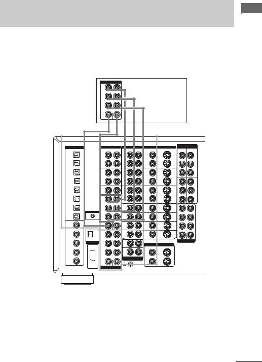
2 Connect the video jacks.
The following illustration shows how to connect a DVD player with COMPONENT VIDEO (Y, PB/ CB/B-Y, PR/CR/R-Y) output jacks. Connecting a TV with component video input jacks allows you to enjoy higher quality video. You can upconvert the video signals, and adjust the hue, etc. of the converted signals (page 38).
Notes
•On this amplifier, standard video signals can be converted to component video and S-video signals, in addition S- video signals can be converted to component video signals. However, you cannot convert component video signals downward to standard video or S-video signals.
•When standard video signals (composite video signals) or S-video signals from a VCR etc. are converted upward on this receiver and then output to your TV, depending on the status of the video signal output, the image on the TV screen may appear distorted horizontally or no image may be output.
TV monitor
|
INPUT |
INPUT |
INPUT |
|
COMPONENT |
S VIDEO |
VIDEO |
R-Y |
B-Y |
Y |
|
DIGITAL |
AUDIO |
|
VIDEO |
|
|
|
OPTICAL |
R |
L |
R |
AUDIO L |
VIDEO |
S2 VIDEO |
VIDEO 1 |
OUT |
|
OUT |
|
OUT |
OUT |
OUT |
|
|
||||
|
TAPE |
|
VIDEO 1 |
|
VIDEO 1 |
|
VIDEO 1 |
IN |
|
IN |
|
IN |
IN |
IN |
|
|
||||
LD |
OUT |
|
OUT |
|
OUT |
OUT |
IN |
|
|
||||
|
MD/DAT |
|
VIDEO 2 |
|
VIDEO 2 |
|
DVD |
IN |
|
IN |
|
IN |
IN |
IN |
|
|
||||
|
|
|
|
|
|
|
TV/SAT |
CD/ |
|
|
|
|
|
IN |
SACD |
|
OUT |
|
OUT |
OUT |
|
IN |
|
|
|
|
|
|
1 |
|
VIDEO 3 |
|
VIDEO 3 |
|
MD/DAT |
|
IN |
|
IN |
IN |
|
OUT |
FRONT |
|
|
|||
|
|
|
|
|
||
|
|
|
VIDEO |
|
VIDEO |
|
MD/DAT |
SURR |
|
4 |
|
4 |
IN |
IN |
OUND |
|
IN |
|
IN |
|
CONTROL A1II
|
CD/SACD |
|
|
SURR |
LD |
LD |
|
|
|
|
IN |
IN |
IN |
||
|
IN |
|
|
BACK |
|||
|
COAXIAL |
|
|
CENTER |
DVD |
DVD |
|
|
|
|
|
|
|||
|
VIDEO 1 |
|
|
|
IN |
IN |
IN |
|
IN |
|
|
SUB |
|||
|
|
|
|
WOOFER |
|
|
|
|
LD |
|
|
2 |
TV/ |
TV/ |
|
|
|
|
|
SAT |
SAT |
IN |
|
|
IN |
|
|
FRONT |
IN |
IN |
|
|
|
|
AUDIO IN |
|
PHONO |
|
|
|
DVD |
|
i.LINK S200 |
|
|
|
|
|
|
SURR |
IN |
|
|
||
|
IN |
|
|
MONITOR OUT |
|||
|
|
|
|
OUND |
|
||
|
|
|
|
|
TUNER |
VIDEO |
S2 VIDEO |
|
|
|
|
|
OUT 1 |
OUT 1 |
|
|
TV/SAT |
|
|
SURR |
|
||
|
|
|
IN |
|
|
||
|
IN |
|
|
BACK |
|
|
|
|
|
|
|
|
|
||
|
|
|
|
CENTER |
R |
L |
|
|
|
|
|
AUDIO |
OUT 2 |
|
|
|
CD/SACD |
|
|
|
OUT 2 |
||
|
|
|
|
|
|
|
|
|
IN |
|
|
SUB |
|
|
|
|
|
|
RS232C |
WOOFER |
|
|
|
|
|
|
MULTI CHANNEL IN |
SIGNAL |
|
|
|
|
|
|
|
|
|
||
|
|
|
|
|
GND |
|
|
|
|
H |
|
C |
D |
|
|
|
OUTPUT |
|
|
OUTPUT |
OUTPUT |
|
|
|
COMPONENT |
|
|
VIDEO |
S VIDEO |
|
|
R-Y |
B-Y |
Y |
|
|
|
|
|
H D C
COMPONENT
VIDEO
DVD |
Y |
Y |
VIDEO 1 |
IN |
IN |
||
PB/CB/B-Y |
PB/CB/B-Y |
||
PR/CR/R-Y PR/CR/R-Y |
|||
TV/ |
|
Y Y |
MONI |
SAT |
|
|
TOR |
IN |
|
|
OUT |
PB/CB/B-Y PB/CB/B-Y
PR/CR/R-Y PR/CR/R-Y
FRONT
SURROUND
SURR BACK
SUB WOOFER |
CENTER |
PRE OUT
DVD player
10GB
1c: Connecting components with only analog audio jacks
Hooking up audio components
For details on the required cords (A–I), see page 5.
OUTPUT |
|
|
|
|
|
INPUT OUTPUT |
|
|
|
|
|
|
|
|
|
INPUT OUTPUT |
|
|
|
AUDIO |
|
|
|
|
|
|
|
|
|
|
|
|
|
|
|
|
|||
|
|
|
|
|
LINE |
LINE |
|
|
|
|
|
|
|
|
|
LINE LINE |
|
|
|
OUT |
CD/Super Audio |
|
|
|
Tape deck |
|
|
|
|
|
|
|
MD/DAT deck |
||||||
L |
|
|
|
|
L |
|
|
|
|
|
|
L |
|
||||||
|
|
CD player |
|
|
|
|
|
|
|
|
|
|
|
|
|
|
|
|
|
R |
|
|
|
|
|
|
|
R |
|
|
|
|
|
|
|
|
R |
|
|
A |
|
|
|
|
|
A |
|
A |
|
|
|
|
|
|
|
A |
A |
||
|
|
|
|
|
OUT |
l |
|
l |
IN |
|
|
|
|
OUT |
l |
l |
IN |
||
DIGITAL |
|
AUDIO |
|
VIDEO |
|
|
|
|
|
|
COMPONENT |
|
|
|
|||||
|
|
|
|
|
DVD |
|
VIDEO |
VIDEO 1 |
|
|
|
||||||||
OPTICAL |
|
|
R |
L |
|
R AUDIO |
L |
|
VIDEO |
S2 VIDEO |
Y |
Y |
|
|
|
||||
|
|
|
|
|
|
|
|
|
|
IN |
|
|
IN |
|
|
|
|||
VIDEO 1 |
|
|
OUT |
|
OUT |
|
|
OUT |
|
OUT |
|
|
|
|
|
|
|
|
|
OUT |
|
|
|
|
|
|
|
|
|
|
|
|
|
|
|
||||
|
|
|
TAPE |
|
VIDEO 1 |
|
VIDEO 1 |
|
|
|
PB/CB/B-Y |
PB/CB/B-Y |
|
|
|
||||
VIDEO 1 |
|
|
IN |
|
IN |
|
|
IN |
|
IN |
|
|
|
|
|
|
|
|
|
IN |
|
|
|
|
|
|
|
|
|
|
|
|
|
|
|
||||
|
|
|
|
|
|
|
|
|
|
|
|
PR/CR/R-Y |
PR/CR/R-Y |
|
|
|
|||
LD |
|
|
OUT |
|
OUT |
|
|
OUT |
|
OUT |
|
|
|
|
|
|
|
|
|
IN |
|
|
|
|
|
|
|
|
|
|
|
|
|
|
|
||||
|
|
|
MD/DAT |
|
VIDEO 2 |
|
VIDEO 2 |
|
TV/ |
|
Y Y |
|
MONI |
|
|
|
|||
|
|
|
|
|
|
|
|
|
|
|
|
|
|
|
|
||||
DVD |
|
|
IN |
|
IN |
|
|
IN |
|
IN |
SAT |
|
|
|
TOR |
|
|
|
|
IN |
|
|
|
|
|
|
IN |
|
|
|
|
OUT |
|
|
|
||||
|
|
|
|
|
|
|
|
|
|
|
|
|
|
|
|
|
|
|
|
|
|
|
|
|
|
|
|
|
|
|
|
PB/CB/B-Y |
PB/CB/B-Y |
|
|
|
|
||
TV/SAT |
|
|
CD/ |
|
|
|
|
|
|
|
|
|
|
|
|
|
|
|
|
IN |
|
|
SACD |
|
OUT |
|
|
OUT |
|
OUT |
|
|
|
|
|
|
|
|
|
|
|
|
IN |
|
|
|
|
|
|
|
|
|
|
|
|
|
|
|
|
|
|
|
1 |
|
VIDEO 3 |
|
VIDEO 3 |
|
|
|
PR/CR/R-Y |
PR/CR/R-Y |
|
|
|
|
|||
MD/DAT |
|
|
|
IN |
|
|
IN |
|
IN |
|
|
|
|
|
|
|
|
|
|
OUT |
|
|
FRONT |
|
|
|
|
|
|
|
|
|
|
|
|
|
|||
|
|
|
|
|
|
|
|
|
|
|
|
|
|
|
|
|
|
||
|
|
|
|
|
VIDEO |
|
|
VIDEO |
|
|
FRONT |
|
|
|
|
|
|
|
|
MD/DAT |
|
|
SURR |
|
4 |
|
|
4 |
|
IN |
|
|
|
|
|
|
|
|
|
IN |
|
|
OUND |
|
IN |
|
|
IN |
|
|
|
|
|
|
|
|
|
|
|
|
|
CONTROL A1II |
|
|
LD |
|
|
LD |
|
|
SURROUND |
|
|
|
|
|
|
||
|
|
|
|
|
|
|
|
|
|
|
|
|
|
|
|||||
CD/SACD |
|
|
SURR |
|
IN |
|
|
IN |
|
IN |
|
|
|
|
|
|
|
|
|
IN |
|
|
BACK |
|
|
|
|
|
|
|
|
|
|
|
|
|
|||
COAXIAL |
|
|
|
CENTER |
DVD |
|
|
DVD |
|
|
SURR BACK |
|
|
|
|
|
|
||
VIDEO 1 |
|
|
|
|
IN |
|
|
IN |
|
IN |
|
|
|
|
|
|
|
|
|
IN |
|
|
SUB |
|
|
|
|
|
|
|
|
|
|
|
|
|
|||
|
|
|
WOOFER |
|
|
|
|
|
|
|
|
|
|
|
|
|
|
|
|
|
|
|
2 |
|
TV/ |
|
|
TV/ |
|
|
SUB WOOFER |
CENTER |
|
|
|
|
|||
LD |
|
|
|
|
|
|
|
|
|
|
|
|
|
|
|
|
|||
|
|
|
|
SAT |
|
|
SAT |
|
IN |
|
|
|
|
|
|
|
|
|
|
IN |
|
|
FRONT |
|
IN |
|
|
IN |
|
|
|
|
|
|
|
|
|
|
|
|
|
AUDIO IN |
|
|
PHONO |
|
|
|
|
|
|
PRE OUT |
|
|
|
|
|
||
DVD |
|
i.LINK S200 |
SURR |
|
|
|
|
|
|
|
|
|
|
|
|
||||
IN |
|
|
|
IN |
|
|
MONITOR OUT |
|
|
|
|
|
|
|
|
|
|||
|
|
|
OUND |
|
|
|
|
|
|
|
|
|
|
|
|
|
|||
|
|
|
|
|
TUNER |
|
|
|
VIDEO |
S2 VIDEO |
|
|
|
|
|
|
|
|
|
|
|
|
|
|
|
|
OUT 1 |
|
OUT 1 |
|
|
|
|
|
|
|
|
|
|
TV/SAT |
|
|
SURR |
|
|
|
|
|
|
|
|
|
|
|
|
|
|
||
|
|
|
IN |
|
|
|
|
|
|
|
|
|
|
|
|
|
|
||
IN |
|
|
BACK |
|
|
|
|
|
|
|
|
|
|
|
|
|
|
|
|
|
|
|
|
|
|
|
|
|
|
|
|
|
|
|
|
|
|
||
|
|
|
|
CENTER |
|
R |
L |
|
|
|
|
|
|
|
|
|
|
|
|
|
|
|
|
|
AUDIO |
|
OUT 2 |
|
|
|
|
|
|
|
|
|
|
|
|
CD/SACD |
|
|
|
|
|
|
|
OUT 2 |
|
|
|
|
|
|
|
|
|
||
|
|
|
|
|
|
|
|
|
|
|
|
|
|
|
|
|
|
|
|
IN |
|
|
SUB |
|
|
|
|
|
|
|
|
|
|
|
|
|
|
|
|
|
|
RS232C |
WOOFER |
|
|
|
|
|
|
|
|
|
|
|
|
|
|
|
|
|
|
MULTI CHANNEL IN |
SIGNAL |
|
|
|
|
|
|
|
|
|
|
|
|
|
|
||
|
|
|
|
|
|
|
|
|
|
|
|
|
|
|
|
|
|||
|
|
|
|
|
GND |
|
|
|
|
|
|
|
|
|
|
|
|
|
|
AA
Turntable |
OUTPUT |
LINE |
L Tuner
R
Note
If your turntable has a ground wire, connect it to the U SIGNAL GND terminal.
Started Getting
continued
11GB
Hooking up video components
If you connect your TV to the MONITOR jacks, you can watch the video from the selected input (page 22). You can also display the SPEAKER SET UP, LEVEL, SURR SET UP, EQUALIZER, CUSTOMIZE menu settings and sound fields on your TV by pressing ON SCREEN on the remote. For details on the required cords (A–I), see page 5.
Camcorder or
TV game
B, D
INPUT OUTPUT |
|
VCR |
|
|
VIDEO |
VIDEO |
|
|
|
IN |
OUT |
|
|
|
AUDIO |
AUDIO |
|
|
|
IN |
OUT |
|
|
|
|
|
L |
INPUT |
OUTPUT |
|
|
|
|
|
|
|
|
S VIDEO |
S VIDEO |
|
|
R |
|
|
B |
B |
D |
OUT L |
L IN |
OUT L |
D
L IN
To the VIDEO 3 INPUT jacks (Front panel)
DIGITAL |
|
AUDIO |
VIDEO |
|
|
|
OPTICAL |
|
R |
L |
R AUDIO L |
VIDEO |
S2 VIDEO |
VIDEO 1 |
|
OUT |
|
OUT |
OUT |
OUT |
OUT |
|
|
||||
|
|
TAPE |
|
VIDEO 1 |
VIDEO 1 |
|
VIDEO 1 |
|
IN |
|
IN |
IN |
IN |
IN |
|
|
||||
LD |
|
OUT |
|
OUT |
OUT |
OUT |
IN |
|
|
||||
|
|
MD/DAT |
|
VIDEO 2 |
VIDEO 2 |
|
DVD |
|
IN |
|
IN |
IN |
IN |
IN |
|
|
||||
TV/SAT |
|
CD/ |
|
|
|
|
IN |
|
SACD |
|
OUT |
OUT |
OUT |
|
|
IN |
|
|
|
|
|
|
1 |
|
VIDEO 3 |
VIDEO 3 |
|
MD/DAT |
|
|
IN |
IN |
IN |
|
OUT |
|
FRONT |
|
|||
|
|
|
|
|
||
|
|
|
|
VIDEO |
VIDEO |
|
MD/DAT |
|
SURR |
|
4 |
4 |
|
IN |
|
OUND |
|
IN |
IN |
IN |
|
CONTROL A1II |
|
|
LD |
LD |
|
CD/SACD |
|
SURR |
|
|
||
|
|
IN |
IN |
IN |
||
IN |
|
BACK |
|
|||
COAXIAL |
|
|
CENTER |
DVD |
DVD |
|
|
|
|
|
|||
VIDEO 1 |
|
|
|
IN |
IN |
IN |
IN |
|
SUB |
|
|||
|
|
|
|
|
||
|
|
WOOFER |
|
|
|
|
LD |
|
2 |
|
TV/ |
TV/ |
|
|
|
|
SAT |
SAT |
IN |
|
IN |
|
FRONT |
|
IN |
IN |
|
|
AUDIO IN |
|
|
PHONO |
|
|
DVD |
i.LINK S200 |
|
|
|
|
|
SURR |
|
IN |
|
|
||
IN |
|
|
MONITOR OUT |
|||
|
|
OUND |
|
|
||
|
|
|
|
TUNER |
VIDEO |
S2 VIDEO |
|
|
|
|
OUT 1 |
OUT 1 |
|
TV/SAT |
|
SURR |
|
|
||
|
|
IN |
|
|
||
IN |
|
BACK |
|
|
|
|
|
|
|
|
|
||
|
|
|
CENTER |
R |
L |
|
|
|
|
AUDIO |
OUT 2 |
|
|
CD/SACD |
|
|
|
OUT 2 |
||
|
|
|
|
|
|
|
IN |
|
SUB |
|
|
|
|
|
RS232C |
WOOFER |
|
|
|
|
|
MULTI CHANNEL IN |
SIGNAL |
|
|
||
|
|
|
|
|||
GND
OUT L |
L IN |
OUT L |
L IN |
|
B |
B |
D |
D B |
D |
INPUT OUTPUT |
INPUT OUTPUT |
OUTPUT |
OUTPUT |
|
VIDEO |
VIDEO |
S VIDEO S VIDEO |
VIDEO |
S VIDEO |
IN |
OUT |
|
OUT |
|
AUDIO |
AUDIO |
|
AUDIO |
|
IN |
OUT |
|
OUT |
|
|
L |
|
|
L |
|
R |
|
|
R |
|
VCR |
|
|
VCR |
COMPONENT
VIDEO
DVD |
Y |
Y |
VIDEO 1 |
IN |
IN |
||
PB/CB/B-Y |
PB/CB/B-Y |
||
PR/CR/R-Y PR/CR/R-Y |
|||
TV/ |
|
Y Y |
MONI |
SAT |
|
|
TOR |
IN |
|
|
OUT |
PB/CB/B-Y PB/CB/B-Y
PR/CR/R-Y PR/CR/R-Y
FRONT
SURROUND
SURR BACK
SUB WOOFER |
CENTER |
PRE OUT
CD
INPUT INPUT
VIDEO |
S VIDEO |
TV monitor
12GB
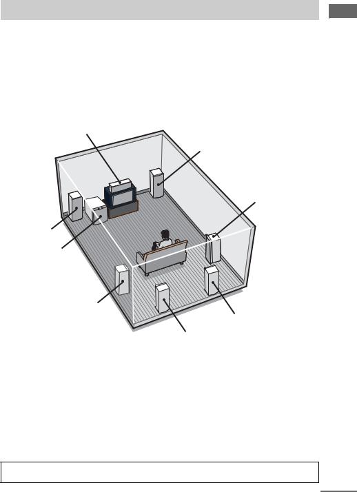
2: Connecting speakers
Connect your speakers to the amplifier. This amplifier allows you to use a 9.1 channel system.
To fully enjoy theater-like multi channel surround sound requires five speakers (two front speakers, a center speaker, and two surround speakers) and a sub woofer (5.1 channel).
You can enjoy high fidelity reproduction of DVD software recorded in the Surround EX format if you connect one additional surround back speaker (6.1 channel) or two surround back speakers (7.1 channel) (see “Selecting the surround back decoding mode” on page 29).
You can even enjoy the 9.1 channel surround sound by connecting four surround speakers (see “Selecting the speaker system” on page 45).
Example of 7.1 channel speaker system configuration
Center speaker
Front speaker (R)
Surround speaker (R)
Front speaker (L)
Sub woofer
Surround speaker (L)
Surround back speaker (R)
Surround back speaker (L)
Tips
•When you connect 6.1 channel speaker system, place the surround back speaker behind the listening position.
•Since the sub woofer does not emit highly directional signals, you can place it wherever you want.
Speaker impedance
To enjoy the best possible multi channel surround, connect speakers with a nominal impedance of 8 ohms or higher to the FRONT, CENTER, SURROUND and SURROUND BACK terminals, and set the IMPEDANCE SELECTOR to “8Ω ”. Refer to the operating instructions supplied with your speakers if you are not sure of their impedance. (This information is often on the back of the speaker.) Alternatively, you may connect speakers with nominal impedances between 4 and 8 ohms to any or all of the speaker terminals. However, be sure to set the IMPEDANCE SELECTOR to “4Ω ” if you connect even one speaker with a nominal impedance between 4 and 8 ohms.
Note
Be sure to turn the power off before adjusting the IMPEDANCE SELECTOR.
continued
Started Getting
13GB
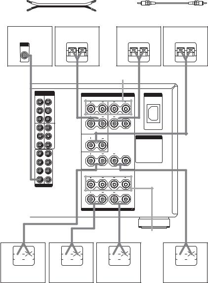
Required cords
A Speaker cords (not supplied) |
|
B Monaural audio cord (not supplied) |
|||||||
(+) |
|
|
|
|
Black |
|
|
|
|
(–) |
|
|
|
|
|
|
|
|
|
Sub woofera) |
|
Surround speaker |
|
Surround speaker |
Center speaker |
||||
|
|
|
(R) |
|
|
|
(L) |
|
|
INPUT |
|
|
|
|
|
|
|
|
|
AUDIO |
|
|
e |
E |
|
E |
e |
e |
E |
IN |
|
|
|
||||||
|
|
|
|
||||||
B |
|
|
A |
SURROUND |
A |
|
A |
||
|
|
|
|
SPEAKERS Bb) |
|
|
|
||
|
COMPONENT |
|
|
|
|
|
|
|
|
|
VIDEO |
|
|
|
SPEAKERS |
|
AC IN |
|
|
DVD |
Y |
VIDEO 1 |
|
|
|
|
|
||
IN Y |
IN |
|
|
SURROUND |
|
|
|
|
|
|
|
|
|
R |
L |
|
|
|
|
|
|
|
|
|
|
|
|
||
PB/CB/B-Y |
PB/CB/B-Y |
|
|
|
|
|
|
|
|
|
|
|
B |
|
|
B |
|
|
|
PR/CR/R-Y PR/CR/R-Y |
|
|
|
|
|
|
|
||
TV/ |
Y Y |
MONI |
A |
|
|
A |
|
|
|
SAT |
|
TOR |
|
|
|
|
|
|
|
IN |
|
OUT |
|
|
|
|
|
|
|
PB/CB/B-Y |
PB/CB/B-Y |
|
|
|
|
|
|
|
|
|
|
|
|
CENTER |
|
AC OUTLET |
|
|
|
|
|
|
|
|
|
|
|
|
|
PR/CR/R-Y PR/CR/R-Y |
|
|
|
|
|
|
|
||
FRONT |
|
|
|
|
SURROUND BACK |
|
|
|
|
|
|
|
|
R |
|
L |
|
|
|
SURROUND |
|
|
|
|
|
|
|
|
|
SURR BACK
SUB WOOFER |
CENTER |
PRE OUT
|
FRONT |
R |
L |
B |
B |
A |
A |
|
|
IMPEDANCE USE 4-16 |
A+B USE 8-16 |
|
|
|
FRONT |
|
A |
A |
A |
SPEAKERS Bc) |
A |
e 
E
e 
E
E
e

E 
e
Surround back |
Front speaker (R) |
Front speaker (L) |
Surround back |
|
speaker (L)d) |
||||
d) |
|
|
||
speaker (R) |
|
|
|
a)When you connect a sub woofer with an auto standby function, turn off the function when watching movies.
b)You can select the surround speakers you want to use with SPEAKERS SURROUND. For details, see “Selecting the speaker system” (page 45).
c)You can select the front speakers you want to use with SPEAKERS FRONT. For details, see “Selecting the speaker system” (page 45).
d)If you connect only one surround back speaker, connect it to the SURROUND BACK SPEAKERS L terminal.
14GB
Tip (Models of area code U, CA only)
To connect certain speakers to another power amplifier, use the PRE OUT jacks. The same signal is output from both the SPEAKERS FRONT jacks and the PRE OUT jacks. For example, if you want to connect just the front speakers to another amplifier, connect that amplifier to the PRE OUT FRONT L and R jacks.
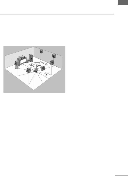
Enjoying the 9.1 channel speaker system
What is the 9.1 channel speaker system?
A large dubbing theater for recording movie soundtracks uses 10 surround speakers. However, in a small dubbing theater, only 2 speakers each are placed on the right, left, and back walls. Thus, the minimum setup for a dubbing theater is 9.1 channels. When SPEAKERS SURROUND is set to A+B, you can enjoy 9.1 channel speaker operation, just like a dubbing theater.
Arrange the speakers around the center of the room based on the angles shown in the illustration on the left. If you are unable to position the speakers according to the angles shown, place one set of surround speakers slightly forward of the listening position (toward the front speakers).
Although the center of the room is used as an axis for determining speaker placement, 9.1 channel speaker operation covers an extremely wide listening area which you can enjoy from anywhere in the room behind the central point.
When using the CINEMA STUDIO EX modes with the 9.1 channel system, be sure to set Virtual Speaker to OFF in SURR SET UP. (You can enjoy the surround effects of movies even without the use of virtual speakers since so many real speakers are used.)
In addition, unlike virtual speakers, the expressive capability of real speakers will vary depending on the speaker. Adjust the effect level so that the actor’s lines sound natural and the impact of sound effects is nicely balanced.
The advantage of a 9.1 channel speaker system is a drastic improvement in the connection between the front (video) sound field and the surround sound field. Previously, we have employed virtual speaker technology to present this sound effect, but a real 9.1 channel multi channel surround system has a much wider effect area so that all family members can enjoy the surround effect. Of course, when seated in the middle of the listening position, you can enjoy the sound exactly as the movie director listened.
Tips for placing speakers
Place surround speakers B between the front speakers and the listening position. Adjusting the position of these speakers improves the connection between the front and surround sound stage.
Started Getting
continued
15GB
Tips for using the 9.1 channel speaker system
You can also use the CINEMA STUDIO EX modes with the 9.1 channel speaker system. In this case, the number of virtual surround speakers doubles (for a total of 12 virtual surround speakers).
However, this large number of speakers may narrow the surround effect area. Thus, it may be more effective to set “VIR.SPEAKERS” in the SURR SET UP menu to “OFF”.
Please note that the front L/R and center speakers are common to all modes, and this function only changes the use of the surround speakers. Depending on how you use SPEAKERS FRONT to switch the front speaker system (A/B), and how you set “CENTER SP” in the SPEAKER SET UP menu (“YES” or “MIX”), you can set up two completely different systems. For example, you can set up a 2 channel or 4 channel speaker system for pure audio sources, and a 7.1 channel speaker system for AV sources.
Please note that in most cases you can use the 9.1 channel setting for Super Audio CD and other pure audio sources without any adjustments. However, depending on the type of speakers you have and the way the music software was recorded, you may want to switch to 7.1 channel or 5.1 channel playback. In such cases, you should set up your surround speaker system to switch between A and B. Use surround speakers B for 5.1 channel operation and surround speakers A+B for 9.1 channel operation.
16GB
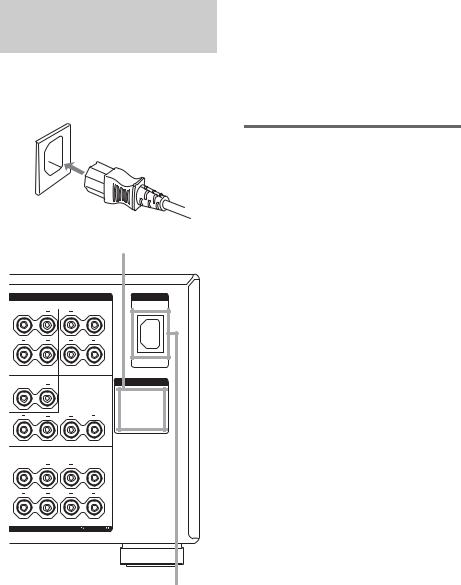
3: Connecting the AC power cord
Connect the supplied AC power cord to the AC IN terminal on the amplifier, then connect the AC power cord to a wall outlet.
AC power cord
|
|
AC OUTLET |
|
SPEAKERS |
AC IN |
R |
SURROUND |
L |
|
||
B |
|
B |
A |
|
A |
|
|
|
CENTER |
AC OUTLET |
|
|
|
|
|
SURROUND BACK |
|
R |
|
L |
|
FRONT |
|
R |
|
L |
B |
|
B |
A |
|
A |
|
|
|
|
IMPEDANCE USE 4-16 |
A+B USE 8-16 |
AC IN terminal
*The configuration, shape, and number of AC outlets vary according to the area code.
Notes
•The AC OUTLET(s) on the rear of the amplifier is a switched outlet, which supplies power to the
connected component only while the amplifier is |
|
|
turned on. |
|
|
• Make sure that the total power consumption of the |
|
|
Getting |
||
component(s) connected to the amplifier’s AC |
||
|
||
OUTLET(s) does not exceed the wattage stated on |
|
|
the rear panel. Do not connect high-wattage |
|
|
electrical home appliances such as electric irons, |
Started |
|
fans, or TVs to this outlet. This may cause a |
||
|
||
malfunction. |
|
Performing initial setup operations
Before using the amplifier for the first time, initialize the amplifier by performing the following procedure.
This procedure can also be used to return settings you have made to their factory defaults.
1 Press ?/1 to turn off the amplifier.
2 Hold down ?/1 for 5 seconds.
“ENTER to Clear ALL” appears in the display for 10 seconds.
3 Press ENTER while “ENTER to Clear ALL” appears in the display.
After “MEMORY CLEARING...” appears in the display for a while, “MEMORY CLEARED!” appears.
The following are reset to their factory settings.
•All settings in the SPEAKER SET UP, LEVEL, SURR SET UP, EQUALIZER, and CUSTOMIZE menus.
•The sound field memorized for each input.
•All index names for inputs.
17GB

4: Setting up the speakers
You can use the SPEAKER SET UP menu to set the size and distance of the speakers connected to this system.
1 Press ?/1 to turn on the system.
2 Rotate MAIN MENU to select “SPEAKER SET UP”.
3 Rotate MENU to select the menu item you want.
For more information, see “Speaker setup parameters”.
Notes
•Certain setup parameters may be dimmed in the display. This means that the selected parameter is either unavailale or fixed and unchangeable due to sound field (pages 27–29) or other settings.
•Some speaker setup items may appear dimmed in the display. This means that they have been adjusted automatically due to other speaker settings. Depending on the settings, you may or may not be able to adjust certain speakers.
4 Rotate –/+ to select the parameter.
5 Repeat steps 3 and 4 until you have set all of the items that follow.
Note
Before setting up the surround speakers, select the surround speakers you use (page 45).
Speaker setup parameters
The initial settings are underlined.
x SP EASY SET UP (Speaker easy setup)
•YES
You can set up your speakers automatically by selecting a pre-defined speaker pattern (see the supplied “Easy Setup Guide”).
•NO
Select to adjust the settings of each speaker manually.
xSPEAKER PATTERN (Speaker setup pattern)
When “SP EASY SET UP” is set to “YES”, select the speaker setup pattern. Rotate –/+ to select the speaker setup pattern and press
ENTER to enter the selection. Check your speaker pattern using the supplied “Easy Setup Guide”.
x SUB WOOFER (Sub woofer)
•YES
If you connect a sub woofer, select “YES”.
•NO
If you did not connect a sub woofer, select “NO”. This activates the bass redirection circuitry and outputs the LFE signals from other speakers.
Tip
In order to take full advantage of the Dolby Digital bass redirection circuitry, we recommend setting the sub woofer’s cut off frequency as high as possible.
x FRONT SP (Front speakers)
•LARGE
If you connect large speakers that will effectively reproduce bass frequencies, select “LARGE”. Normally, select “LARGE”. When the sub woofer is set to “NO”, front speakers are automatically set to “LARGE”.
•SMALL
If the sound is distorted, or you feel a lack of surround effects when using multi channel surround sound, select “SMALL” to activate the bass redirection circuitry and output the front channel bass frequencies from the sub woofer. When the front speakers are set to “SMALL”, the center, surround and surround back speakers are also automatically set to “SMALL” (unless previously set to “NO”).
x CENTER SP (Center speaker)
•LARGE
If you connect a large speaker that will effectively reproduce bass frequencies, select “LARGE”. Normally, select “LARGE”. However, if the front speakers are set to “SMALL”, you cannot set the center speaker to “LARGE”.
•SMALL
If the sound is distorted, or you feel a lack of surround effects when using multi channel surround sound, select “SMALL” to activate the bass redirection circuitry and output the center channel bass frequencies from the front speakers (if set to “LARGE”) or sub woofer.
18GB
 Loading...