


3-858-580-12(1)
MD Multi-Track
Recorder
Operating Instructions |
|
EN |
||
|
|
|||
|
|
|
|
|
Mode d’emploi |
|
|
|
F |
|
|
|
|
|
|
|
|
|
|
Bedienungsanleitung |
|
|
D |
|
|
|
|
||
 T
T
MDM-X4
© 1996 by Sony Corporation
WARNING
To prevent fire or shock hazard, do not expose the unit to rain or moisture.
This symbol is intended to alert the user to the presence of uninsulated “dangerous voltage” within the product’s enclosure that may be of sufficient magnitude to constitute a risk of electric shock to persons.
This symbol is intended to alert the user to the presence of important operating and maintenance (servicing) instructions in the literature accompanying the appliance.
To avoid electrical shock, do not open the cabinet. Refer servicing to qualified personnel only.
Do not install the appliance in a confined space, such as a bookcase or built-in cabinet because the mains power switch (MAIN POWER) is located on the rear panel.
This appliance is classified as a CLASS 1 LASER product. The CLASS 1 LASER PRODUCT MARKING is located on the rear exterior.
INFORMATION
This equipment has been tested and found to comply with the limits for a Class B digital device, pursuant to Part 15 of the FCC Rules.
These limits are designed to provide reasonable protection against harmful interference in a residential installation. This equipment generates, uses, and can radiate radio frequency energy and, if not installed and used in accordance with the instructions, may cause harmful interference to radio communications. However, there is no guarantee that interference will not occur in a particular installation. If this equipment does cause harmful interference to radio or television reception, which can be determined by turning the equipment off and on, the user is encouraged to try to correct the interference by one or more of the following measures:
-Reorient or relocate the receiving antenna.
-Increase the separation between the equipment and receiver.
-Connect the equipment into an outlet on a circuit different from that to which the receiver is connected.
-Consult the dealer or an experienced radio/TV technician for help.
CAUTION
You are cautioned that any change or modifications not expressly approved in this manual could void your authority to operate this equipment.
Owner’s record
The model and serial numbers (name plate) are located on the bottom of the unit. Record the serial number in the space provided below. Refer to them whenever you call upon your Sony dealer regarding this product.
Model No. MDM-X4
Serial No.
For the customers in Canada
This Class B digital apparatus meets all requirements of the Canadian Interference-Causing Equipment Regulations.
Cet appareil numérique de la classe B respecte toutes les exigences du Réglement sur le matériel brouilleur du Canada.
CAUTION
TO PREVENT ELECTRIC SHOCK, DO NOT USE THIS POLARIZED AC PLUG WITH AN EXTENSION CORD, RECEPTACLE OR OTHER OUTLET UNLESS THE BLADES CAN BE FULLY INSERTED TO PREVENT BLADE EXPOSURE.
Precautions
On safety
•Caution - The use of optical instruments with this product will increase eye hazard.
•Should any liquid or solid object fall into the unit, unplug the unit and have the unit checked by qualified personnel before operating it any further.
On power sources
•Before operating the unit, be sure that the operating voltage of your unit is identical with that of your local power supply.
•Unplug the unit from the wall outlet if it is not to be used for an extended period of time. To disconnect the cord, pull it out by grasping the plug. Never pull the cord itself.
•AC power cord must be changed only at the qualified service shop.
•The unit is not disconnected from the AC power source (mains) as long as it is connected to the wall outlet, even if the unit itself has been turned off.
On placement
•Place the multi track recorder in a location with adequate ventilation to prevent heat buildup in the multi track recorder.
•Do not place the unit in an inclined position.
•Do not place the unit in locations where it is:
–Extremely hot or cold
–Dusty or dirty
–Very humid
–Vibrating
–Subject to direct sunlight.
On cleaning the cabinet
Clean the cabinet, panels and controls with a soft cloth lightly moistened with a mild detergent solution. Do not use any type of abrasive pad, scouring powder or solvent such as alcohol or benzine.
2EN

On repacking
Do not throw away the carton and the packing material. This makes an ideal container when transporting the unit.
When shipping the unit, repack it as it was packed at the factory.
On operation
•If the multi track recorder is brought directly from a cold to a warm location , or is placed in a very damp room, moisture may condense on the lens inside the MD deck. Should this occur, the system will not operate properly. Remove the MD and leave the system turned on for about an hour until the moisture evaporates.
•When you move the system, take out the disc.
On handling MDs
•Do not open the shutter to expose the MD. Close the shutter immediately if the shutter opens.
•Wipe the disc cartridge with a dry cloth to remove dirt.
•Do not expose the MD to direct sunlight or heat sources such as hot air ducts, nor leave it in a car parked in direct sunlight.
Protecting a recorded MD
To record-protect an MD, slide open the tab at the side of the MD so the tab is concealed.
In this position, the MD cannot be recorded. To record on the MD, slide close the tab.
On requesting repairs
The nameplate is located on the bottom exterior.
If you have any question or problem concerning your unit that is not covered in this manual, please consult your nearest Sony dealer.
About This Manual
The following icon is used in this manual:
 Indicates hints and tips for making the task easier.
Welcome!
Thank you for purchasing the Sony MD Multi-Track Recorder. Before operating the unit, please read this manual thoroughly and retain it for future reference.
TABLE OF CONTENTS
Overview of MDM-X4
Standard Recording Procedures .................................................................................. |
4 |
Names and Functions of Parts
The Mixer......................................................................................................................... |
6 |
The Recorder ................................................................................................................... |
8 |
The Display ................................................................................................................... |
10 |
Input and Output Jacks ............................................................................................... |
11 |
Connections and Signal Flow
Connections for Recording ......................................................................................... |
13 |
Connecting MIDI Equipment .................................................................................... |
14 |
MDM-X4 Signal Flow Diagram ................................................................................. |
14 |
Monitoring
Monitoring Preparations ............................................................................................ |
15 |
Monitoring Example .................................................................................................... |
15 |
Setting Up the Operating Environment
System Settings ............................................................................................................. |
17 |
Changing the Settings ................................................................................................. |
18 |
Recording
Initial Recording ........................................................................................................... |
19 |
|
|
|
Overdub Recording ..................................................................................................... |
20 |
|
|
|
Auto Punch-In/Out Recording ................................................................................. |
22 |
|
|
|
Manual Punch-In/Out Recording ............................................................................ |
25 |
|
|
|
EN |
||||
Mix Write Recording (Basics) .................................................................................... |
27 |
|
||
...........................................................Mix Write Recording (Applied Operations) |
28 |
|
|
|
Editing Part of a Song (Track Edit) |
31 |
|
|
|
Track Edit Overview ................................................................................................... |
|
|
||
Specifying the Locate Points ...................................................................................... |
31 |
|
|
|
Copying a Part (Track Copy) ..................................................................................... |
33 |
|
|
|
Moving a Part (Track Move) ...................................................................................... |
34 |
|
|
|
Switching the Location of 2 Parts (Track Exchange) ............................................. |
35 |
|
|
|
Erasing a Part (Track Erase) ....................................................................................... |
36 |
|
|
|
Changing the Construction of a Song (Section Edit) |
38 |
|
|
|
Section Edit Overview ................................................................................................. |
|
|
||
Specifying the Locate Points ...................................................................................... |
38 |
|
|
|
Moving a Section (Section Move) .............................................................................. |
39 |
|
|
|
Switching the Location of 2 Sections (Section Exchange) ..................................... |
40 |
|
|
|
Inserting Another Section (Section Insert) .............................................................. |
41 |
|
|
|
Deleting a Section (Section Delete) ........................................................................... |
42 |
|
|
|
Editing Entire Songs (Song Edit) |
43 |
|
|
|
Song Edit Overview ..................................................................................................... |
|
|
||
Copying a Song (Song Copy) ..................................................................................... |
43 |
|
|
|
Moving a Song (Song Move) ...................................................................................... |
44 |
|
|
|
Changing the Song Order (Song Exchange)............................................................ |
45 |
|
|
|
Dividing a Song (Song Divide) .................................................................................. |
46 |
|
|
|
Connecting 2 Songs (Song Combine) ....................................................................... |
47 |
|
|
|
Deleting a Song (Song Delete) ................................................................................... |
48 |
|
|
|
Naming a Song (Song Name) .................................................................................... |
49 |
|
|
|
Editing the Entire Disc (Disc Edit) |
50 |
|
|
|
Overview ....................................................................................................................... |
|
|
||
Erasing the Disc Contents (Disc Erase) .................................................................... |
50 |
|
|
|
Naming the Disc (Disc Name) ................................................................................... |
51 |
|
|
|
Synchronization with MIDI Equipment |
52 |
|
|
|
Advantages of Using MIDI ........................................................................................ |
|
|
||
MIDI Synchronization Using MTC ........................................................................... |
52 |
|
|
|
MIDI Synchronization Using the MIDI Clock ........................................................ |
53 |
|
|
|
Controlling This Unit from Other MIDI Components Using MMC ................... |
55 |
|
|
|
Example of a MIDI System ......................................................................................... |
56 |
|
|
|
Mixdown |
57 |
|
|
|
Mixdown (Basics) ......................................................................................................... |
|
|
||
Mixdown (Applied Operations) ................................................................................ |
58 |
|
|
|
Additional Information |
60 |
|
|
|
Troubleshooting ........................................................................................................... |
|
|
||
Display Message List ................................................................................................... |
60 |
|
|
|
System Limitations of MDs ........................................................................................ |
61 |
|
|
|
Specifications ................................................................................................................ |
61 |
|
|
|
Glossary ......................................................................................................................... |
63 |
|
|
|
Block Diagram .............................................................................................................. |
64 |
|
|
|
MIDI Implementation Chart ...................................................................................... |
65 |
|
|
|
Track Sheet ................................................................................................... |
Back Cover |
|
||
3EN
Overview of MDM-X4
Standard Recording
Procedures
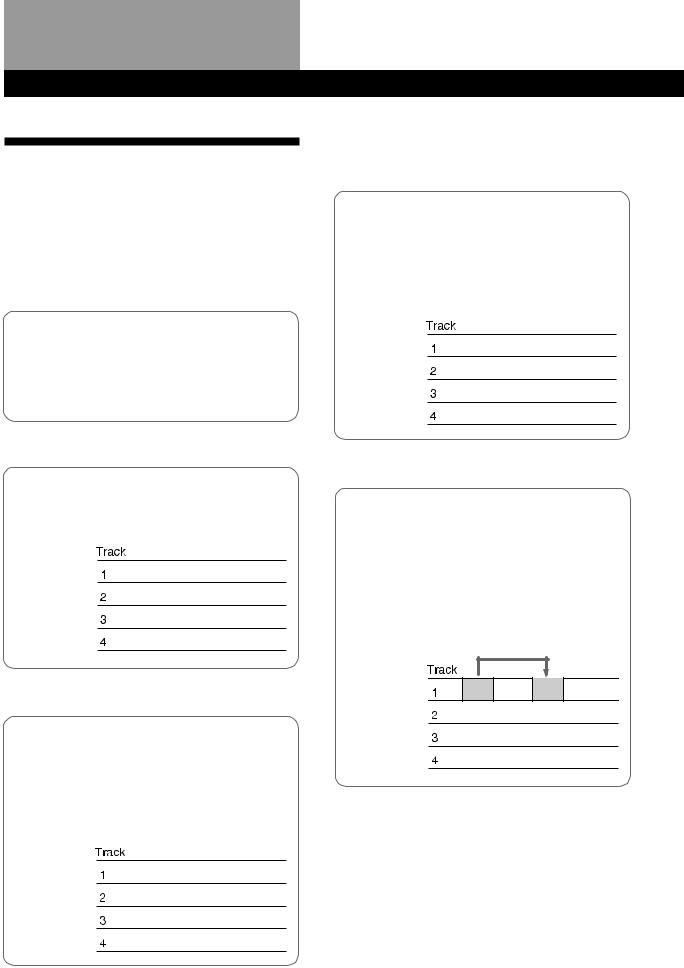
The MDM-X4 is an integrated multichannel recorder/ mixer that can record up to 4 tracks using MD-DATA discs. In addition to 4 track recording and playback, this unit can also perform a variety of editing operations.
1Connect instruments, microphones, effectors, (etc.) and prepare for recording.
See “Connections and Signal Flow” (page 13)
for details. µ
2 Record the first track.
Example : Record the drums to track 1.
See “Initial Recording” (page 19) for details.
Drums n
µ
3Record another instrument on a different track while listening to the previously recorded track.
Example: Record the bass to track 2, the guitar to track 3 and the vocals on track 4.
See “Overdub Recording” (page 20) for details.
Drums
Bass n
Guitar n
Vocal n
µ
4You want to add a harmony chorus, but there’s no more tracks left!
No problem! If you've already used all 4 tracks, you can record on top of a previously recorded track.
See “Mix Write Recording” (page 27) for details.
Drums
Bass
Guitar
Vocal NChorus
µ
5You realize that a certain drum fill would sound better in a different place.
You can move, copy, or delete part of the song. For example, if the first and second chorus were reversed, they can easily be switched.
See “Editing Part of a Song (Track Edit)” (page 31) for details.
4EN
Overview of MDM-X4
µ
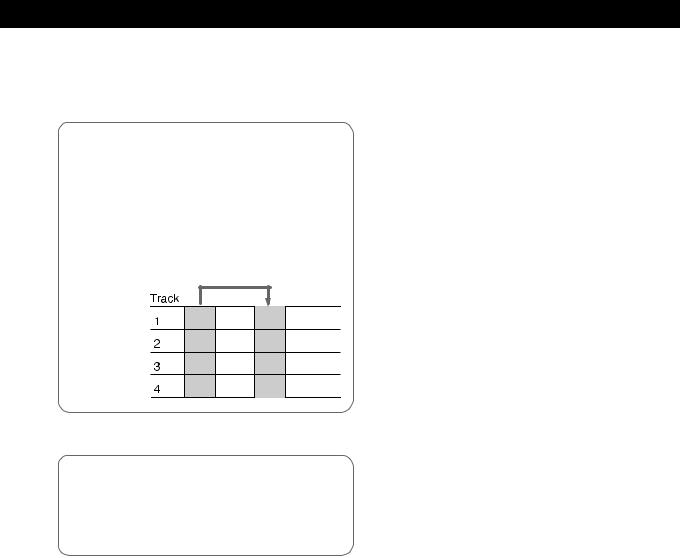
6You decide you want to change the structure of the song.
The edit functions let you add (or remove) an extra chorus or repeat the introduction in the middle of the song (etc.) without having to rerecord.
See “Changing the Construction of a Song (Section Edit)” (page 38) for details.
µ
7Dub the tracks onto an external MD or DAT deck while using the mixer to adjust the balance.
See “Mixdown” (page 57) for details.
µ
Done !
Other convenient functions
•Equipped with an easy to use Jog/Shuttle dial.
•The Auto Punch-In/Out function lets you rerecord part of a song by enabling the record mode automatically only during the part which you have specified.
See “Auto Punch-In/Out Recording” (page 22) for details.
•The Undo function lets you revert to the previous state when an edit operation doesn’t produce the desired effect.
•Synchronization with other MIDI equipment is also possible. In addition to the ability to synchronize this unit with an external sequencer at start-up, you can also remote control this unit from the sequencer (with MMC compatible equipment only).
The synchronization functions also let you make recordings by using a computer or sequencer to mediate sounds from acoustic instruments, like vocals or guitar, recorded on this unit with sounds from other MIDI equipment and sound modules (etc.).
See “Synchronization with MIDI Equipment” (page 52) for details.
•The Pitch Control function enables precise speed control.
See the “SYSTEM key” explanation in “Names and Functions of Parts” (page 9) for details.
•A 10 INPUT/4 BUS analog mixer with exceptional sound quality.
5EN
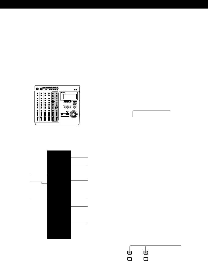
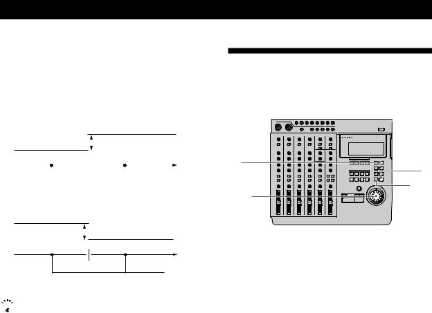
Names and Functions of Parts
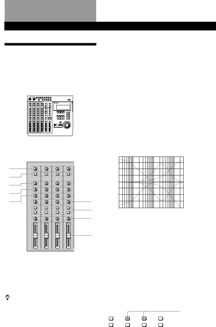
The Mixer
Also refer to the “Block Diagram” on page 64.
The Channel 1~4 Section
The functions described are the same for each channel (1~4).
.
1
2
3
4
5 |
6 |
7
8
9
1 TRIM knobs
Allow you to adjust the level of the signals input into the INPUT CH1~CH4 jacks approximately 40 dB. Turn to the right to increase the input level.
Normally, if you connect an instrument, turn to LINE; if you connect a microphone, turn to MIC.
For the best sound characteristics, adjust the TRIM knob so that the proper level is obtained when the fader is set between 7 and 8.
6EN
2 INPUT selector keys
Allow you to select either LINE/MIC (sound from the INPUT CH jacks) or TRACK 1~4 (sound from the recorder) for input to mixer channels 1~4. LINE/MIC : Use to input external sounds from an
instrument or microphone (etc.).
TRACK 1~4 : Use to input sounds played back from the recorder.
3 HIGH knobs
Adjust the treble of the respective channel. Provide a shelving type equalization.
4 MID knobs
Adjust the middle frequencies of the respective channel. Provide a peak type equalization.
5 LOW knobs
Adjust the bass of the respective channel. Provide a shelving type equalization.
HIGH/MID/LOW equalizer (dB) characteristic curves
20.0
15.0
10.0
5.0
0
–5.0
–10.0
–15.0
–20.0
20 |
100 |
1k |
10k |
20k (Hz) |
6 AUX knobs
Adjust the level of the sound sent to the AUX bus (1~2) from the respective channel. Turn to “1” to output the sound from the respective channel to AUX bus 1. Turn to “2” to output the sound from the respective channel to AUX bus 2.
When set to the center position, no sound is output from either AUX bus.
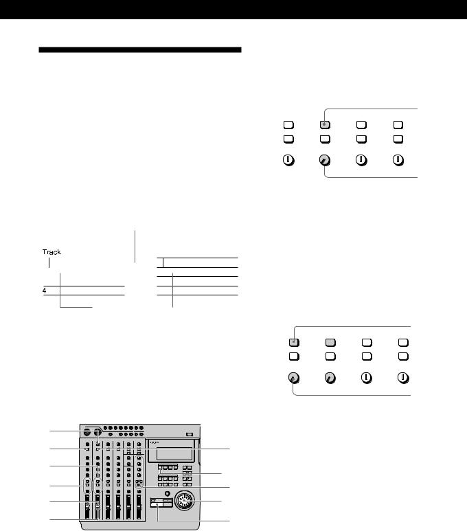
7 ASSIGN keys
Determine which group bus the channels will be assigned to (which track on the recorder they will be recorded to).
The channel signal is always connected to the stereo bus
Example: To assign the sounds from channels 2 and 3 to group bus 1. (To record them to track 1 of the recorder).
Press down
ASSIGN |
ASSIGN |
ASSIGN |
ASSIGN |
||||
1 |
2 |
1 |
2 |
1 |
2 |
1 |
2 |
3 |
4 |
3 |
4 |
3 |
4 |
3 |
4 |
Names and Functions of Parts
8 PAN knobs
Adjust the sound balance of the stereo or group bus. Turn towardsÊ “L” to move the sounds toward group bus 1 or 3 and the “L” side of the stereo bus. Turn towards “R” to move the sounds toward group bus 2 or 4 and the “R” side of the stereo bus.
9 Faders 1~4
Adjust the volume of each channel.
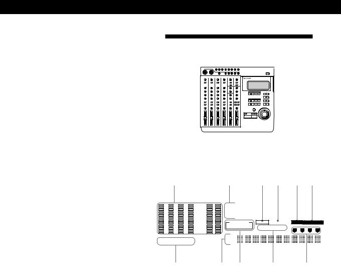
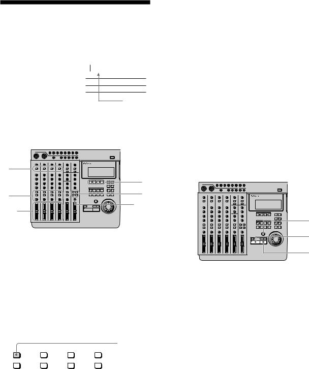
Channel 5,6 and MASTER
3 LOW knob
Adjusts the bass of the sound input to the INPUT 5/6 jacks at the top of the unit. Provides a shelving type equalization.
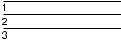
4 ASSIGN keys
Determines which group bus the sounds input to the INPUT 5/6 jacks at the top of the unit will be assigned to (which track on the recorder they will be recorded to).
Channel 5 can only be assigned to group bus 1 or 3. Channel 6 can only be assigned to group bus 2 or 4.
EXAMPLE: To assign the sounds from channels 5 and 6 to group bus 1 and 2 respectively. (To record them to track 1 and 2 of the recorder).
Press down
ASSIGN 1  2
2
3  4
4
|
. |
|
7 |
|
8 |
1 |
|
2 |
9 |
3 |
|
4 |
0 |
5 |
!Á |
6 |
!ª |
5 BALANCE knob
Adjusts the relative balance of channels 5 and 6. Rotate toward “L” to increase the volume of channel 5. Rotate toward “R” to increase the volume of channel 6.
6 Fader 5/6
Simultaneously adjusts the volume of both channels 5 and 6.
7 RETURN knobs (1 and 2)
Adjust the volume of the sound input into the RETURN 1 and 2 jacks at the top of the unit. (Return sound is generally used for adding external effects.)
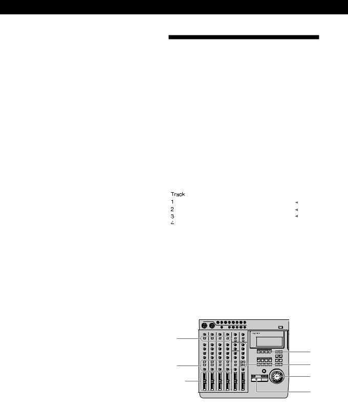
8 ASSIGN keys
Determine which group bus (1~4) the return sounds will be assigned to (which track on the recorder they will be recorded to).
Example: To assign the sounds from return 1 and 2 to group bus 1 and 2. (To record them to tracks 1 and 2 on the recorder).
Press down
1 MASTER AUX 1~2 knobs
Adjust the master level of the AUX bus sound output from the AUX OUTPUT 1~2 jacks.
2 HIGH knob
Adjusts the treble of the sound input to the INPUT 5/6 jacks at the top of the unit. Provides a shelving type equalization.
ASSIGN |
ASSIGN |
||
1 |
2 |
1 |
2 |
3 |
4 |
3 |
4 |
(continued)
7EN

Names and Functions of Parts
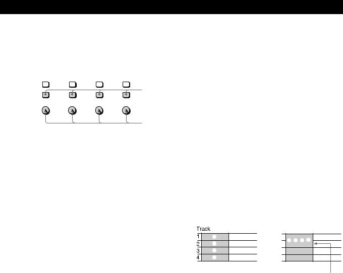
9 TRACK 1~4 knobs
Use to adjust the overall sound balance when monitoring playback from the recorder (CUE monitor) by turning the knob for each track as desired. When using the CUE monitor function, be sure to press down the monitor track setting
0 Monitor Track Setting Select the sound to be
1–2 : Press down to monitor 1 and 2.
3–4 : Press down to monitor 3 and 4.
CUE : Press down to monitor recorder. Use the TRACK volume of the individual
STEREO : Press down to stereo bus.
!Á MONITOR knob Adjusts the volume of the MONITOR OUT jacks (on HEADPHONES jack (on
!ª MASTER fader Adjusts the volume of the from the STEREO OUT
8EN
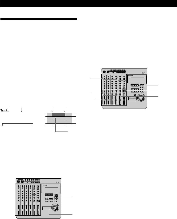
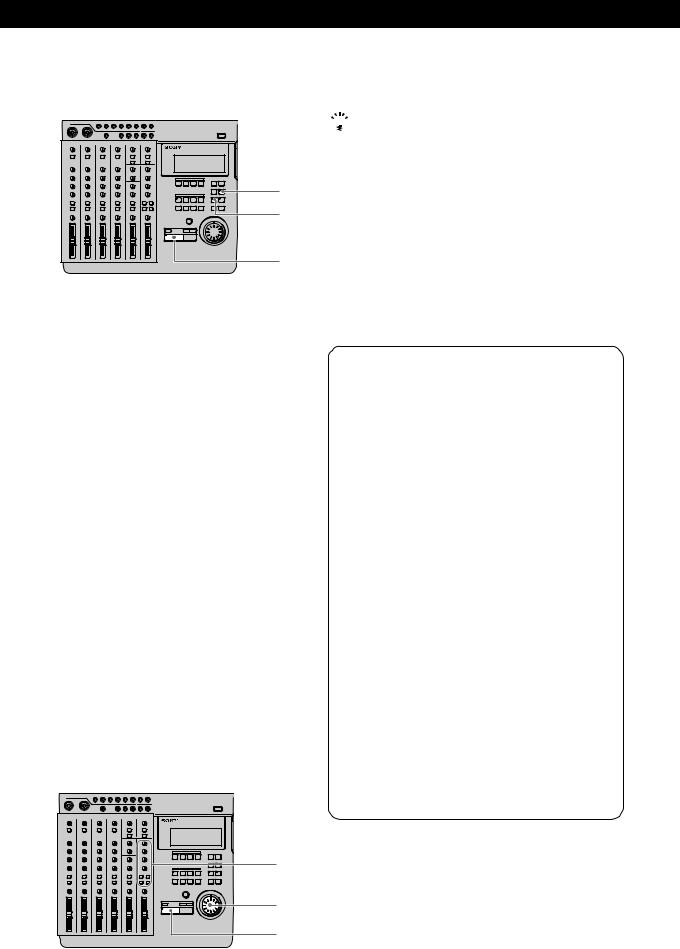
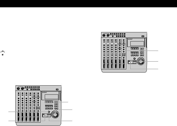
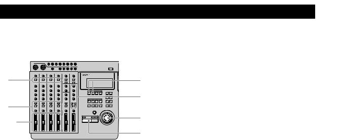
The Recorder
Control Panel
1 REC SELECT 1~4 keys
Press to light the corresponding track indicator(s) and select the track(s) to be recorded. These keys also function as in/out keys during manual punch-in/out recording.
2 SHIFT key
Holding down this key when you press another key lets you carry out the function written below the respective key.
EXAMPLE: The REPEAT key
•When pressed alone, it functions as the REPEAT key
•When pressed while holding down SHIFT, it functions as the DISPLAY key.

3 OUT key
Sets the out point (edit end point).
4 IN/DEST key
Sets the in point (edit start point).
Press while holding down SHIFT to set the destination point (edit destination point).
5 MARK key
Press to set a mark point (and the key starts blinking). Press IN, OUT, DEST, or A~H while the MARK key is blinking to set the mark point to the respective key.
This unit lets you assign up to 11 mark points using IN, OUT, DEST, and A~H.
6 Locate point keys
Press to recall mark points. To specify points E~H, press the respective key while holding down SHIFT.
7 REC key
Press to enter record mode. The key blinks, to indicate record pause mode. The key lights steadily when recording.
8 =/+keys
Press to locate the beginning of the previous or next song. When adjusting a mark point, they can also be used with the rehearsal function to switch between a volume increase or decrease after the mark point.
9 TOP key
Press once to locate the beginning of the first song on the disc. Press again during stop mode to locate the beginning of the unrecorded (blank) part of the disc.
0 (PLAY key
Starts playback. Lights during playback.
!Á pSTOP key
Stops recording or playback.
Hold down this key and press the (PLAY key to activate the IN-OUT playback mode and play back the section between the IN and OUT points repeatedly. Pressing this key during stop mode to write the TOC data* to the disc.
!ª ¤ EJECT key
Press to remove the disc.
If the TOC data* has not been written to the disc, it will be written automatically before the disc is ejected.
*You must write the TOC data to disc after a SECTION edit, SONG edit, or DISC edit. See pages 38 and 44 for details.
!£ Disc insertion slot Insert the disc into this slot.
Names and Functions of Parts
!¢ REPEAT/DISPLAY key
Press to activate the repeat playback mode. The repeat mode changes as follows each time you press the key:
•REPEAT : Repeats all the songs on the disc.
•REPEAT 1 : Repeats the current song.
•1 : Plays the current song once. After playback, the unit locates the beginning of the song.
•(no indicator) : Off. Plays all of the songs on the disc. Press while holding down SHIFT to change the display mode as follows:
•Time Mode : Shows the counter display in time.
•Bar Mode : Shows the counter display in bars.
•Remaining Mode : Shows the amount time which can be recorded remaining on the disc.
Note
Numbers will not be displayed in bar mode, if no tempo information is input.
!° EDIT key
Press to enter Edit mode. Edit mode can only be entered when the disc is in stop mode.
!¤ SYSTEM key
This key has two functions.
•System setting
Press when making system settings to enter the system settings. See “Changing a Setting” (page 18) for details.
•Pitch Control
Press while holding down SHIFT to turn the recording/playback pitch control “on”. Press again while holding down SHIFT to turn the recording/ playback pitch control “off”.
Pitch control “on” : Recording or playback is conducted in the preset pitch. (“Vari Pitch” is displayed.)
Pitch control “off” : Recording or playback is conducted in the normal pitch. (“Fixed Pitch” is displayed.)
See “System Settings” (page 17) for details on the pitch setting.
(continued)
9EN
Names and Functions of Parts
!¦ RHSL (Rehearsal) key This key has two functions:
•Record rehearsal (rehearsal function)
Press during record pause mode to cause the indicator to blink and set this unit to operate as if it were recording, without actually recording. This is called rehearsal mode. (Rehearsal mode can also be activated by pressing RHSL when the AUTO PUNCH key is lit.)
During record rehearsal, all other operations will function as if the unit was recording. This provides a convenient way to practice without actually
recording.
Press pSTOP to cancel the rehearsal mode. Rehearsal mode, however, is not activated when recording a new song.
•Locate point adjustment (locate adjust function) Press to light the indicator and repeat the section just before and after the current locate point. The repeat time is specified in the roll time setting. Turning the JOG dial during rehearsal lets you adjust the position of the locate point.
Press pSTOP to cancel the locate adjust mode. See “Correcting the position of the locate point” (page 32) for details.
Note
During locate adjust mode the counter value does not change to reflect the position of the playback sound.
Use JOG or SHUTTLE to adjust the counter value/position of the respective locate point. However, if you do not register the new value as a mark point it will be erased after the adjustment.
!¥ UNDO key
Erases the previous edit or auto punch-in/out operation and returns the data to its original status. See “Using the Undo Function” (pages 24, 31, 38, 43) for details.
!» ENTER key
Press to carry out the selected operation (etc.).
@¼ EXIT key
Press to cancel the selected operation or to exit the edit mode.
@Á AUTO PUNCH key
Use to select the auto punch-in/out function.
@ª Jog dial (Jog/Shuttle dial)
Use to search (find a specific point within a song), select items from menus, set parameters, and adjust locate point positions (etc.).
The smallest increment in which a locate point can be adjusted is one click of the jog dial (approx. 11.6 msec).
The Display
.
1
|
|
|
|
CLIP |
|
|
|
|
– 3 |
|
|
|
|
– 6 |
|
|
|
|
–12 |
|
|
|
|
–20 |
|
|
|
|
–30 |
1 |
2 |
3 |
4 |
–40 |
(dB) |
R R R R
7
2 |
3 4 5 6 |
|||||
|
BAR |
BEAT |
|
|
|
CLK |
000MIN 00SEC |
00FRM |
|||||
SYNC-OUT |
MMC |
REPEAT 1 |
EDIT |
SYSTEM |
||
MIDI-CLK MTC |
IN/OUT PLAY |
1 |
2 |
3 |
4 |
|
|
||||||
|
|
|
||||
L R |
SONG |
|
STEREO NO. |
||
8 9 0 !Á
1 Level meters
•1~4
During playback : Display the output levels of each track on the disc.
During recording : Display the input levels of the track(s) being recorded.
During stop mode or when no disc is inserted : Displays the volume of group bus 1~4.
•L, R
Displays the volume of the stereo bus.
2 Counter display
Displays the time (minute/second/frame) or bar (bar/ beat/clock).
3 MMC indicator
Lights when the unit can receive MMC (MIDI Machine Control) signals.
4 REPEAT indicator
Light during repeat playback.
“REPEAT” lights when repeating all the songs on the disc, “REPEAT1” lights when repeating one song.
10EN
5 [EDIT] indicator
Lights during edit operations (track, section, song, disc).
6 [SYSTEM] indicator
Lights during system setting operations.
7 R indicators
Lights to indicate that the respective track was selected for recording using the REC SELECT keys. The track number corresponds to the group bus number.
8 Title display area
Displays the song or disc title, as well as edit menu information.
9 SYNC-OUT indicator
Displays the currently selected output synchronization. See pages 17 and 52~56 for details.
MIDI–CLK : Lights when the MIDI clock is being output.
MTC : Lights when the MIDI time code is being output.
0 IN/OUT PLAY indicator Lights during IN/OUT playback.
!Á Track display indicator
Displays the source track during editing.
Names and Functions of Parts
Input and Output Jacks
Top panel
.
12
34
1 TRACK 1~4 output jacks
Output the sound from tracks 1~4 of the recorder. The TRACK 1~4 jacks output the signals for each track as they were recorded onto the disc.
Previously recorded signals are played back and output, even when the recorder is recording.
2 RETURN 1 / 2 (L (MONO) /R) input jacks Use to input signals from external sources.
For example, when sending a sound modified by an external effect back to the mixer.
Use the L (MONO) jack when inputting monaural signals.
3 CH 1~6 input jacks
Use to input sounds to channels 1~6. The CH 1~4 jacks are for signals from microphones or line level sources. The CH 5 and 6 jacks are for line level signals only.
Channel 1 and 2 allow direct connection of XLR type plugs. (Channels 1 and 2 are balanced inputs for both XLR and standard plugs.)
(continued)
11EN

Names and Functions of Parts
4 OUTPUT AUX 1/2 jacks
Output sound for use as the send output. After adding an outboard effect to the sound output from these jacks, use the RETURN 1/2 (L/R) jacks to input it back to this unit.
Rear Panel
1 2 3
456
1 MIDI THRU jack
Outputs the same signal input to the MIDI IN jack.
2 MIDI OUT jack
Outputs the MIDI signal. Connect to the MIDI IN jack of another piece of MIDI equipment.
3 MIDI IN jack
Inputs the signals output from the MIDI OUT jack of another piece of MIDI equipment.
4 Power switch
Use to turn the power of this unit on and off.
5 MONITOR OUT jack
Outputs the sound of the monitor bus. Connect to a pair of monitor speakers or an amplifier.
See “Connections for Recording” (page 13) for details.
6 STEREO OUT jack
Outputs the sound of the stereo bus. Connect to a DAT deck (etc.) during mixdown.
See “Connections for Recording” (page 13) for details.
Front Panel
12
1 HEADPHONES jack
Connect a pair of headphones with a standard type plug.
2 ASSIGN SW 1,2 jack
For connecting external switches, such as a foot switch (etc.).
See “System Settings” (page 17) for details regarding the functions which can be controlled.
You can use either 
 or
or 
 type foot switches. When the power is turned on, this unit registers the current position of the connected pedal as “OFF”.
12EN
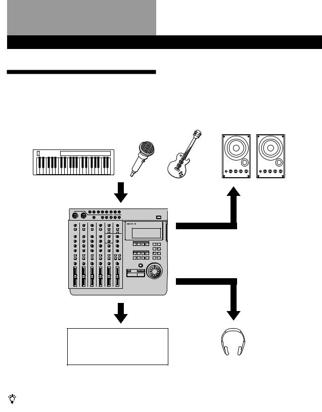
Connections and Signal Flow
Connections for Recording
Connect instruments, microphones, and amp and headphones for monitoring as shown below.
Instruments or microphones
To INPUT CH1~CH 6 jacks (You can use XLR type plugs with CH-1 and CH-2)
From the STEREO OUT jacks on the rear panel of this unit
Recording equipment for use in mixdown
•DAT recorder
•MD recorder
When inputting sound from a sound module into this unit
You can mix the sound with sounds previously recorded on tracks 1~4 by using the INPUT CH-5 or INPUT CH-6 jacks.
Do the following when connecting an external effector to input the return sound.
To output sound to the effector : Use the AUX 1 or AUX 2 jacks on the top panel of this unit.
To input sound from the effector (return sound) : Use the RETURN 1 or RETURN 2 jacks on the top panel of this unit.
External amplifier and speakers
From the MONITOR OUT jacks on the rear panel of this unit
From the HEADPHONES jacks on the front panel of this unit
Headphones for monitoring
Turning on the Power
After you have completed all connections, connect the power cord from this unit to a wall outlet.
13EN

Connections and Signal Flow
Connecting MIDI Equipment
Connect MIDI equipment as shown in the following diagram.
For details regarding connections for synchronized operation with a sequencer (etc.), see “Synchronization with MIDI Equipment” (pages 52~56).
Sequencer (etc.)
MIDI IN jack |
MIDI OUT jack |
MIDI OUT jack |
MIDI IN jack |
||||||||||||||||||||||||||
|
|
|
|
|
|
|
|
|
|
|
|
|
|
|
|
|
|
|
|
|
|
|
|
|
|
|
|
|
|
|
|
|
|
|
|
|
|
|
|
|
|
|
|
|
|
|
|
|
|
|
|
|
|
|
|
|
|
|
|
|
|
|
|
|
|
|
|
|
|
|
|
|
|
|
|
|
|
|
|
|
|
|
|
|
|
|
|
|
|
|
|
|
|
|
|
|
|
|
|
|
|
|
|
|
|
|
|
|
|
|
|
|
|
|
|
|
|
|
|
|
|
|
|
|
|
|
|
|
|
|
|
|
|
|
|
|
|
|
|
|
|
|
|
|
|
|
|
|
|
|
|
|
|
|
|
|
|
|
|
|
|
|
|
|
|
|
|
|
|
|
|
|
|
|
|
|
|
|
|
|
|
|
|
|
|
|
|
|
|
|
|
|
|
|
|
|
|
|
|
|
|
|
|
|
|
|
|
|
|
|
|
|
|
|
|
|
|
|
|
|
|
|
|
|
|
|
|
|
|
|
|
|
|
|
|
|
|
|
|
|
|
|
|
|
|
|
|
|
|
|
|
To output the MIDI |
MIDI THRU jack |
|||
signal input to this unit’s |
||||
|
|
|||
MIDI IN jack directly to |
|
|
||
other MIDI equipment. |
|
|
||
|
|
|
||
|
External sound module (etc.) |
|
||
|
|
|
|
|
MDM-X4 Signal Flow Diagram
The following diagram shows the internal signal flow of this unit.
1 


 3
3 4
4
2 

1 Input external sounds.
2The input sound is recorded after being mixed and assigned to the respective group bus (1~4).
3The playback sound from the recorder is input back into the mixer (mix write recording, bounce recording).
4The playback sound from the recorder is output to an external component, that adds an effect, before being input back into the mixer (mix write recording, bounce recording).
This unit’s 6 channel inputs and 2 stereo return inputs are connected to group bus 1~4 and stereo bus L/R. (For group bus 1~4 use the ASSIGN keys to assign the input sound to a group bus. The channel signals are always connected to the stereo bus. In cases where you do not want to mix the signals to the stereo bus, lower the faders for the respective channels to “0”.)
When monitoring, you can select group bus 1-2, group bus 3-4, stereo bus, or TRACK 1~4 OUTPUT (CUE bus).
For details on how to monitor, see “Monitoring Example” (page 15).
14EN
Monitoring
Monitoring Preparations
This unit enables you to monitor the following 4 types of signals as necessary.
1Group 1, 2 : Select to monitor mixer group bus 1 and
2.The sound from group bus 1 is localized in the L (left) channel and the sound from group bus 2 is localized in the R (right) channel. When recording,
select to monitor the sound being recorded.
2Group 3, 4 : Select to monitor mixer group bus 3 and
4.The sound from group bus 3 is localized in the L (left) channel and the sound from group bus 4 is localized in the R (right) channel. When recording, select to monitor the sound being recorded.
3CUE : Select to listen to all the sound recorded on the disc. You can adjust the volume level of the individual tracks using the TRACK 1~4 knobs located above the MONITOR keys. (All tracks are
heard in mono.) When recording, the track being recorded is muted.
4STEREO : Select to listen to the sound of the mixer’s stereo bus. For use during mixdown (etc.).
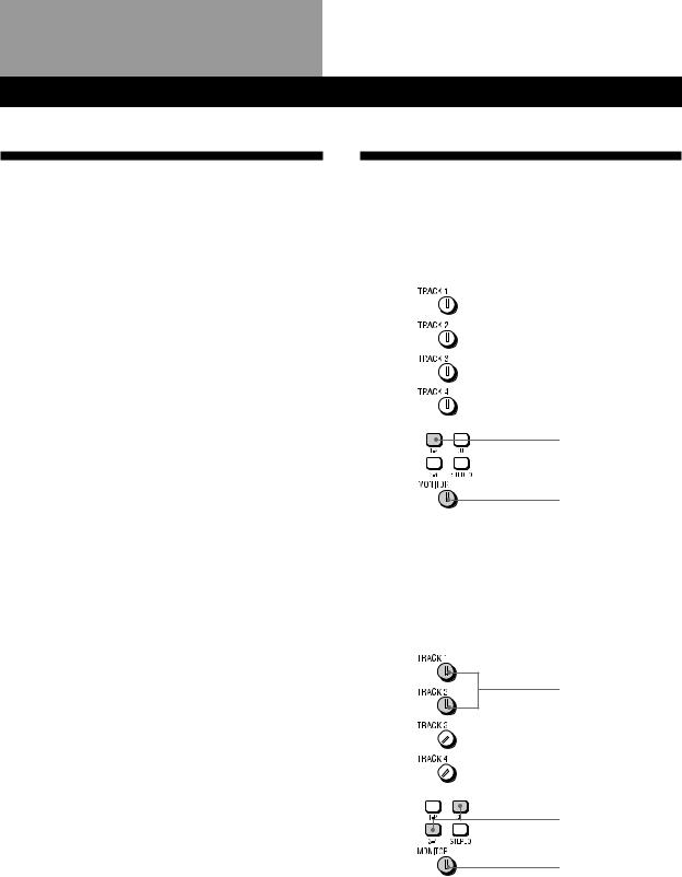
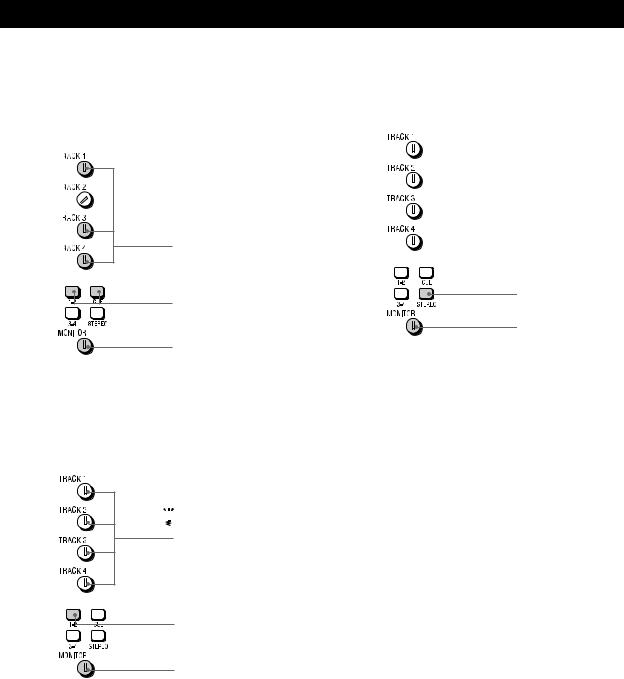
Monitoring Example
EXAMPLE 1: Monitoring the sound from group bus 1 and 2 (during recording, etc.)
Press down
Turn to adjust level
EXAMPLE 2: Monitoring the sound being recorded to tracks 3 and 4 while monitoring the sound of tracks 1 and 2 (during overdubbing, etc.)
Turn to adjust level
Press down
Turn to adjust level
(continued)
15EN
Monitoring
EXAMPLE 3: Rerecording part of track 1 while monitoring the sound of tracks 3 and 4 (during punch-in/out recording, etc.)
EXAMPLE 5: Monitoring the sound of the stereo bus (for mixdown, etc.)
Turn to adjust level
Press down
Press down
Turn to adjust level
Turn to adjust level
EXAMPLE 4: Mixing tracks 1~4 for recording onto tracks 1 and 2 (during mix write recording, etc.)

 You do not need to use the CUE monitor
This operation uses the mixer for mixing.
Press down
Turn to adjust level
16EN

Setting Up the Operating Environment
System Settings
You customize the operating environment by turning the MIDI synchronization and UNDO (undo last operation) functions (etc.) on or off.
Pitch setting (Pitch)
You can set the pitch in 0.25% increments within a range of ±8%. When you turn the pitch control on after setting the pitch , recording/playback is conducted at the selected pitch.
See the “System key” in “Names and Functions of Parts” (page 9) for details on turning the pitch control on/off.
MMC setting (MMC)
This sets the MMC (MIDI Machine Control) reception. See page 55 for details about MMC.
off : No reception. Use this setting when using this unit by itself.
on : The unit operates according to the received MMC signals.
Device ID setting (Dev ID)
Sets the MMC ID number. It can be set to any number between 0 and 126. When this unit receives ID = 127 signals, they are registered as a valid signals regardless of this unit’s ID setting.
Synchronized output source setting (Sync)
Sets the Synchronized output source. See pages 52 and 53 for details about synchronization.
off : Does not output a synchronization signal MTC (MIDI Time Code) : When using the MTC for
synchronization.
MCLK (MIDI Clock) : When using the MIDI clock for synchronization.
MTC frame number setting (Frame)
Sets the MTC frame number (per second). You can select either 25 or 30 non-drop frames.
Assignable switch 1, 2 setting (Sw-1, Sw-2)
Allows you to assign one of the following commands for control by the external switch connected to the ASSIGN SW1 or SW2 jack on the front panel.
Play : Same function as this unit’s (PLAY key. RecIO : Press once for the same function as the REC
key (punch-in). Press again for the same function as the (PLAY key (punch-out). This setting allows you to conduct punch in-out recording from an external switch.
Stop : Stops the disc operation.
IOply (In-Out Play) : Starts IN-OUT playback PlayS (Play-Stop) : Press one to start playback, press
again to stop playback.
Rec S (Rec-Stop) : Press once to start recording, press again to stop recording.
Pre-roll/Post-roll setting (Roll)
Allows you to set the pre-roll/post-roll time used during rehearsal (locate point adjustment) and auto punch-in/out operations in 1 second increments. It is adjustable from 1 to 10 seconds.
Undo function on/off setting (Undo)
This determines whether the undo function will be on or off when you use auto punch-in/out. During edit mode, however, the undo function is always on. Changing this setting also changes the redo function (that allows you to undo the undo) setting is also changed at the same time.
Disabl (off) : Turns off the undo function Enabl (on) : Turns on the undo function
The indicator on the UNDO key has the following meanings:
GREEN : You can use the undo function. (blinking) : Preparing to carry out the undo
function.
RED : Undo (or Redo) has been carried out. (off) : You cannot use the undo function (such as
when the previous operation cannot be undone (etc.)).
See page 24 for details about using the undo function with the auto punch-in/out function.
Note
Do to the limitations of this system, if the blank space on the disc becomes too small it may not be possible to use the undo function even if it is set to “on”. In this case, the indicator on the UNDO key will be off. Be sure to check whether this indicator is on or off before performing an edit operations.
Recordable track number setting (Rec)
This sets the number of tracks to be used on the disc. The number of tracks selected is effective the next time a song is recorded. During playback, the number of tracks is selected automatically according to the source disc.
The selectable tracks also differ depending on the type of disc you use (MD DATA or music MD).
Rec Mode |
Usable |
Recording |
Usable |
|
tracks |
time |
Discs |
4 |
1~4 |
37 min. |
MD DATA |
2 |
1, 2 |
74 min. |
MD DATA, |
|
|
|
Music MD |
|
|
|
|
1 |
1 |
148 min. |
MD DATA, |
|
|
|
Music MD |
|
|
|
|
Note
The Rec Mode automatically switches to 2 track for music MDs (even if it was previously set to the 4 track mode). After recording on a music MD, be sure to reset the Rec Mode to 4 track when you want to make a 4 track recording using a MD DATA disc.
(continued)
17EN
Setting Up the Operating Environment
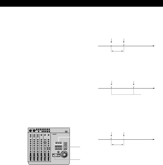
Rehearsal mode setting (RHSL)
This setting lets you determine whether the volume will increase or decrease after the locate point when adjusting the position of a locate point with the rehearsal function. See page 32 for details about locate point adjustment.
å: the volume increases past the locate point.

 Volume increases
|
|
|
|
|
|
|
|
|
|
|
|
|
|
|
|
|
Locate point |
|
Rehearsal |
||||
|
|
|
|
|
|
||
|
|
|
|
|
|
period |
|
µ: the volume decreases past the locate point.
Volume decreases 

Locate point
Rehearsal period
 During rehearsal mode, press the = or + key to switch between increased or decreased volume after the locate point.
Display brightness setting (Dimmer)
Adjusts the display brightness. You can choose from 8 levels (1~8). Larger numbers provide a brighter display.
Changing a Setting
Use the following operations to change the system settings
1
3
5,6
2,4
1Press SYSTEM.
[SYSTEM] appears in the display.
2Turn the jog dial to display the item you want to adjust.
The item blinks in the display.
3Press ENTER.
The blinking moves to the right of the item.
4Turn the jog dial to display the setting you desire.
5Press EXIT.
The item starts blinking again.
6Press EXIT again.
[SYSTEM] disappears from the display.
To reset this unit to the original factory settings
1Turn off the power to this unit.
2Hold down SYSTEM while turning the power back on.
The power comes on and “Initialized” appears in the display. The system settings are reset to the original factory settings.
18EN
|
|
|
|
|
|
|
Recording |
Recording |
|
|
|
|
|
|
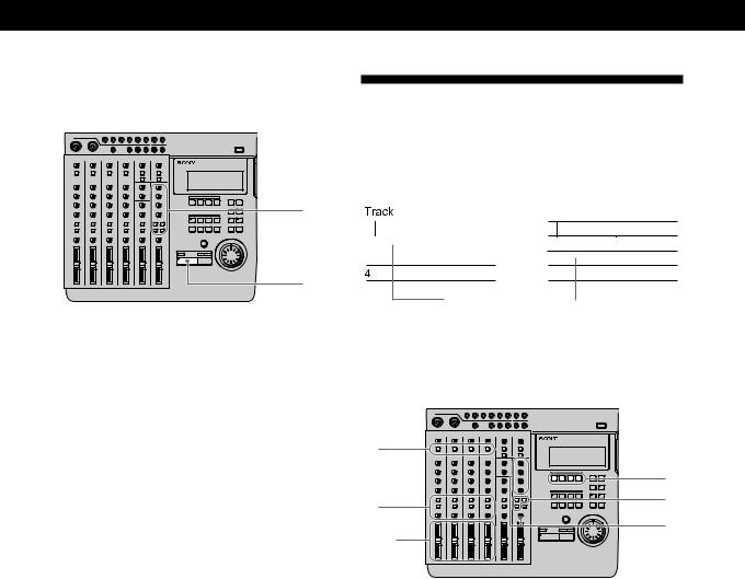
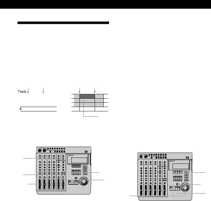
Initial Recording
This shows you how to record the very first track onto a blank disc.
Track
|
b |
|
|
|
1 |
|
|
|
|
2 |
|
|
|
|
3 |
|
|
|
|
4 |
|
|
|
|
Recorded section
Preparations
6Turn the MONITOR knob to adjust the sound to a level which can be monitored.
7Use the fader to adjust the recording level. Play a relatively loud phrase and make adjustments by watching the level meter for the track you want to record.
If necessary, you can use the TRIM knob to adjust the recording level and equalizer.
Adjust the recording level so that the CLIP indicator does not light.
Adjust the TRIM knob so that the proper level is obtained when the fader is set between 7 and 8 to achieve good frequency characteristics.
8Turn the MONITOR knob as in step 6 to adjust monitor level.
1 |
|
|
4 |
3 |
5 |
2,7 |
6,8 |
|
1Set the INPUT switch for the channel to which you will input the instrument or microphone sound to LINE/MIC (up position).
2Set the fader for the channel to which you will input the sound to about 7 or 8.
3Use the ASSIGN switch and PAN knobs to direct the sound to the group path you want to record.
EXAMPLE: To assign channel 1 to group path 1
Press down
ASSIGN |
ASSIGN |
ASSIGN |
ASSIGN |
||||
1 |
2 |
1 |
2 |
1 |
2 |
1 |
2 |
3 |
4 |
3 |
4 |
3 |
4 |
3 |
4 |
4Press the REC SELECT key corresponding to the group path number you selected in step 3 to specify the track to be recorded.
5Press the monitor track set key corresponding to the group path number you selected in step 3.
Recording
1
2
3
1Press REC.
The unit switches to record pause mode.
2Press (PLAY. Recording begins
3When you’ve finished playing, press pSTOP. This unit automatically goes to the beginning of the recorded song.
It takes a few seconds for the unit to process the information after pressing pSTOP.
Please note that the length of the song is fixed at the point where the initial recording ends.
Note
Do not turn off the power during recording. Not only may you loose the data for the current song, you may loose all of the data on the disc.
(continued)
19EN
Recording
Checking the Recording
1 |
2 |
1Press CUE to prepare for monitoring.
Adjust the monitor volume using the respective TRACK knobs and the MONITOR knob.
2Press ( PLAY. Playback begins.
If necessary, you can use the jog dial to locate a specific point.
To rerecord
Follow the “Recording” procedure on the previous page.
Overdub Recording
You can record other sound on a different track while listening to the playback from a previously recorded track. This kind of recording is called overdubbing.


 b
b


Recorded section |
|
Section |
|
||
|
|
recorded by |
|
|
overdubbing |
Preparations
1 |
|
|
|
4 |
|
3 |
5 |
|
6 |
||
2,7 |
||
|
1Set the INPUT switch for the channel to which you will input the instrument or microphone sound to LINE/MIC (up position).
2Set the fader for the channel to which you will input the sound to about 7 or 8.
3Use the ASSIGN switch and PAN knobs to direct the sound to the group path you want to record.
4Press the REC SELECT key corresponding to the group path number you selected in step 3 to specify the track to be recorded.
5Press the monitor track set key corresponding to the group path number you selected in step 3.
6Press CUE, then turn the TRACK knob corresponding to the track containing the recorded sound you want to hear while recording to adjust the sound to a level at which it can be monitored.
Use the MONITOR knob to adjust the monitor level.
20EN
Recording
7Use the fader to adjust the recording level. Play a relatively loud phrase and make adjustments by watching the level meter for the track you want to record.
If necessary, you can use the TRIM knob to adjust the recording level and equalizer.
Adjust the recording level so that the CLIP indicator does not light.
Adjust the TRIM knob so that the proper level is obtained when the fader is set between 7 and 8 to achieve good frequency characteristics.
Recording
1
2
3
1Press REC.
The unit switches to record pause mode.
2Press ( PLAY. Recording begins.
Play together with the previously recorded performance.
3When you’ve finished playing, press pSTOP. If you press pSTOP in the middle of the song,
recording stops at that counter position.
If you do not press pSTOP in the middle of the song, recording stops automatically at the end of the song and the beginning of the song is recalled automatically.
Note
Do not turn off the power during recording. Not only may you loose the data for the current song, you may loose all of the data on the disc.
Checking the Recording
2
1
3
1Turn the jog dial to set the counter to the point you want to hear.
 If you set it as a locate point, it can be located immediately with the LOCATE keys.
2Press CUE to prepare for monitoring.
Adjust the monitor volume using the respective TRACK knobs and the MONITOR knob.
3Press (PLAY. Playback begins.
To rerecord
Follow the “Recording” procedure to the left.
21EN
Recording
Auto Punch-In/Out Recording
You can rerecord a certain portion of a previously recorded track. This is called punch-in/out recording. With this unit allows for 2 kinds of punch-in/out recording; auto punch-in/out, where you specify the section you desire and the unit punches in/out automatically, and manual punch-in/out, where you time the performance and punch-in/out manually at the positions you desire.
With auto punch-in/out recording, only the space between the in and out points is recordable. Therefore, you can play normally over the track but only the specified phrase will be rerecorded. The other parts of the track remain untouched.
EXAMPLE: Using punch-in/out on track 1.
Before punch-in/out |
After punch-in/out |
||
Punch in |
Punch out |
Punch in |
Punch out |
mark |
mark |
mark |
mark |


 b
b


Only this area is recorded.
Setting the section to be punched in/out
Before auto punch-in/out recording you must set the record start (punch in) and record stop (punch out) positions. The punch-in/out positions must be set within the same song. Also, be sure to set the out point at a higher number than the in point.
2


 3 1
3 1

4
1Press (PLAY. Playback begins.
2At the point you want to start recording, press MARK then press IN.
The punch in position is set at the point where you press IN.
3At the point you want to stop recording, press MARK then press OUT.
The punch out position is set at the point where you press OUT.
4Press pSTOP. Playback stops.
Preparations
1 |
|
|
|
4 |
|
3 |
5 |
|
6 |
||
2,7 |
||
|
1Set the INPUT switch for the channel to which you will input the instrument or microphone sound to LINE/MIC (up position).
2Set the fader for the channel to which you will input the sound to about 7 or 8.
3Use the ASSIGN switch and PAN knobs to direct the sound to the group path you want to record.
4Press the REC SELECT key corresponding to the group path number you selected in step 3 to specify the track to be recorded.
5Press the monitor track set key corresponding to the group path number you selected in step 3.
6Turn the MONITOR knob and the TRACK knob corresponding to the track containing the recorded sound you want to hear while recording to adjust the sound to a level which can be monitored.
22EN
7Use the fader to adjust the recording level. Play a relatively loud phrase and make adjustments by watching the level meter for the track you want to record.
If necessary, you can use the TRIM knob to adjust the recording level and equalizer.
Adjust the recording level so that the CLIP indicator does not light.
Adjust the TRIM knob so that the proper level is obtained when the fader is set between 7 and 8 to achieve good frequency characteristics.
Rehearsing the punch-in/out
You can check to make sure the record start (punch in) and record stop (punch out) positions are correct before starting punch-in/out recording. (rehearsal function)
When the rehearsal function is operative, the specified section is muted through the CUE monitor (the actual sound has not been erased). If the settings are incorrect re-specify the in and out points until the correct section has been specified. See “Correcting the position of the locate point” (page 32) for details.
The following procedure shows how to carry out the rehearsal.


 2
2
1
3
1Press AUTO PUNCH when the disc is in stop mode.
The indicator on AUTO PUNCH lights up. REC and the indicator on RHSL start blinking, and the unit enters record pause mode.
When “Undo Function On/Off” in the system settings is set to “Enabl (on)”, the indicator on the UNDO key changes accordingly.
2Press the REC SELECT key for the track to be recorded.
Recording
3Press (PLAY.
Playback starts pre-rolling from a point slightly before the punch-in position in accordance with the “Pre-roll/Post-roll” system setting.
Start of playback Punch in position
Pre-roll time setting
When using CUE monitor, the sound between the punch-in and punch-out positions of the track to be recorded (the track whose REC SELECT key was pressed) cannot be heard.
Punch in position |
Punch out position |
No sound between these points.
Rehearsal post-rolls to a point slightly after the punch out position in accordance with the “Pre- roll/Post-roll” system setting and then stops.
Once rehearsal has stopped, the disc automatically returns to the original point where the AUTO PUNCH key was pressed.
Punch out position End of playback
Post-roll time setting
To stop in the middle of rehearsal
Press pSTOP.
(continued)
23EN
Recording
Recording
2
1
3
1Press AUTO PUNCH when the disc is stopped. The indicator on AUTO PUNCH lights.
REC and the indicator on RHSL start blinking, and the unit enters record pause mode. When “Undo Function On/Off” in the system
settings is set to “Enabl (on)”, the indicator on the UNDO key changes accordingly.
2Press RHSL to cancel rehearsal mode.
When “Undo Function On/Off” in the system settings is set to “Enabl (on)”, and undo is possible, the unit proceeds to back up the data.
3Press (PLAY.
Playback begins. Play together with the previously recorded performance.
When the recorder arrives at the preset punch-in position, record mode is activated automatically and the input sound is recorded on the specified track up to the punch-out point. When the recorder reaches the punch-out point, recording stops automatically, but playback continues until the post-roll point is reached.
When playback is stopped the player automatically returns to the original point.
Checking the Recording
2
1
3
1Turn the jog dial to set the counter to the point you want to hear.
 Pressing the IN key automatically locates the punch-in point.
2Press CUE to prepare for monitoring.
Adjust the monitor volume using the respective TRACK knobs and the MONITOR knob.
3Press ( PLAY. Playback begins.
To rerecord
Follow the “Recording” procedure to the left.
Using the UNDO function with auto punch-in/out recording
You can undo the punch-in/out immediately after execution if the system UNDO setting is set to “Enabl (on)” and the undo indicator is lit green. To carry out the undo function, press UNDO. Pressing undo again lets you redo the undone section (redo function).
Note
Carrying out another edit operation, starting a recording, or removing the disc after carrying out the undo or redo functions will make it impossible to undo the previous edit operation.
Notes about the color of the indicator on the UNDO key.
The color which the indicator on the UNDO key lights shows the current status. (Sometimes the indicator is off).
GREEN : undo is possible. (Redo has been carried out.)
RED : undo has been carried out
(blinking) : in the process of carrying out the undo (or redo) function.
(off) : undo is not possible. (In cases where the previous operation cannot be undone (etc.).)
24EN
Manual Punch-In/Out
Recording
Manual punch-in/out recording is when you start and stop recording manually with the appropriate timing instead of presetting the section to be recorded.
EXAMPLE: To punch-in/out a section on track 1.
Before punch-in/out |
After punch-in/out |
||
Punch in |
Punch out |
Punch in |
Punch out |
mark |
mark |
mark |
mark |


 b
b


Only this area is recorded.
Preparations
Recording
5Press CUE, then turn the TRACK knob corresponding to the track containing the recorded sound you want to hear while recording to adjust the sound to a level which can be monitored.
Use the MONITOR knob to adjust the monitor level.
6Use the fader to adjust the recording level. Play a relatively loud phrase and make adjustments by watching the level meter for the track you want to record.
If necessary, you can use the TRIM knob to adjust the recording level and equalizer.
Adjust the recording level so that the CLIP indicator does not light.
Adjust the TRIM knob so that the proper level is obtained when the fader is set between 7 and 8 to achieve good frequency characteristics.
Recording
(1) Using the REC key to punch-in/out.
1 |
|
|
3 |
4,5 |
|
5 |
||
2,6 |
||
|
1Set the INPUT switch for the channel to which you will input the instrument or microphone sound to LINE/MIC (up position).
2Set the fader for the channel to which you will input the sound to about 7 or 8.
3Use the ASSIGN switch and PAN knobs to direct the sound to the group path you want to record.
4Press the monitor track set key corresponding to the group path number you selected in step 3.
|
1 |
|
3,4 |
2,4 |
5 |
|
1Press the REC SELECT key corresponding to the group path you want to record to specify the track to be recorded.
2Turn the jog dial to set the counter to a position
before the point where you want to start recording, then press ( PLAY.
Playback begins.
3When you reach the point where you want to start recording (the punch in point), press REC.
The REC key lights up and recording begins.
(continued)
25EN
Recording
4Press (PLAY when you reach the point where you want to stop recording (the punch out point). The REC key goes out and the unit stops recording and switches to playback mode.
5Press pSTOP. Playback ends.
 Setting the ASSIGN SW on the front of the unit to “REC IO” lets you use a foot switch (etc.) to activate punchin/out recording. See “System Settings” (page 17) for details.
(2) Using the REC SELECT key to punch-in/out
|
3,4 |
4,5 |
1 |
|
|
2,4 |
5 |
1Turn the jog dial to set the counter to a position before the point where you want to start recording, then press REC.
The REC key start blinking and the unit switches to record pause mode.
2Press (PLAY.
Playback starts, while the REC key continues blinking.
3When you reach the point where you want to start recording (the punch in point), press the REC SELECT key for the track you want to record. The REC key lights steadily and recording begins on the specified track.
4When you reach the point where you want to stop recording (the punch out point), press REC
SELECT key for the track being recorded or press the (PLAY key.
The REC key starts blinking, or goes out, and the unit stops recording and switches to playback mode.
5Press pSTOP. Playback ends.
Checking the Recording
2
1
3
1Turn the jog dial to set the counter to the point you want to hear.
2Press CUE to prepare for monitoring.
Adjust the monitor volume using the respective TRACK knobs and the MONITOR knob.
3Press ( PLAY. Playback begins.
To rerecord
Follow the “Recording” procedure on the previous page.
26EN
Mix Write Recording (Basics)
You can record other sounds on top of a previously recorded track.
The following is an explanation of the mix write concept.
EXAMPLE: Recording a chorus on top of the vocals recorded on track 1.
Since the vocals recorded on track 1 are all assigned to channel 1, connect the microphone to another channel’s input jack.
During recording, the chorus vocals are mixed with the original vocals and recorded to track 1.
Record chorus


 b
b


Previously |
|
Chorus / |
|
||
recorded vocals |
|
vocal mix |
Preparations for recording
EXAMPLE: Recording a chorus on top of the vocals recorded on track 1. (For this example we will input the chorus to the INPUT CH2 jack.)
7 |
|
|
4 |
1 |
|
3 |
11 |
|
5 |
||
6 |
||
9 |
10 |
|
2 |
8 |
1Set the channel 2 INPUT switch to LINE/MIC (up position).
(Set channel 2 to receive the input sound).
2Set the fader for channel 2 to about 7 or 8.
Recording
3Set the channel 2 ASSIGN switch and PAN knobs to direct the sound to track 1.
(Set the chorus vocals input from channel 2 to be recorded on track 1.)
Press down
ASSIGN |
ASSIGN |
ASSIGN |
ASSIGN |
||||
1 |
2 |
1 |
2 |
1 |
2 |
1 |
2 |
3 |
4 |
3 |
4 |
3 |
4 |
3 |
4 |
PAN |
|
PAN |
PAN |
|
PAN |
|
|
L |
R |
L |
R |
L |
R |
L |
R |
Turn all the way toward “L”.
4Press down the channel 1 INPUT switch. (Input the playback sound from the recorder (TRACK 1) to channel 1.)
5Set the channel 1 ASSIGN switch and PAN knobs to direct the playback sound from the recorder to track 1.
(Set the playback sound from the recorder to be recorded on track 1.)
|
|
|
|
|
|
Press down |
ASSIGN |
ASSIGN |
ASSIGN |
ASSIG |
|||
1 |
2 |
1 |
2 |
1 |
2 |
1 |
3 |
4 |
3 |
4 |
3 |
4 |
3 |
PAN |
|
PAN |
PAN |
|
PAN |
|
L |
R |
L |
R |
L |
R |
L R Turn all the |
|
|
|
|
|
|
way toward |
|
|
|
|
|
|
“L”. |
6Prepare the monitor.
•Press the monitor track key corresponding to the group path selected in steps 3 and 5 (in this case, press down the 1-2 button).
•If you want to monitor the sound of tracks 2 and 3 press the CUE key.
•Turn the MONITOR knob and the TRACK knob(s) to adjust the sound to a level that can be monitored.
7Input a loud phrase and use the channel 2 TRIM knob to adjust the recording level.
8Press (PLAY. Playback begins.
(continued)
27EN
Recording
9Use the channel 1 and 2 faders to adjust the balance between the vocals and chorus to be recorded on track 1.
You may also need to adjust the monitor balance
at this time.
Press the pSTOP key after making the necessary adjustments.
10Turn the jog dial to locate the point on the counter where the recording will begin.
11Press the REC SELECT key for track 1. This makes it possible to record on track 1.
Recording
1Press REC.
The unit switches to record pause mode.
2Press (PLAY. Recording begins.
Play together with the previously recorded performance.
3When you’ve finished playing, press pSTOP.
Checking the Recording
1Turn the jog dial to set the counter to the point you want to hear.
2Press CUE to prepare for monitoring.
Adjust the monitor volume using the respective TRACK knobs and the MONITOR knob.
3Press (PLAY. Playback begins.
Mix Write Recording (Applied
Operations)
Mix write also comes in handy in a variety of other situations not mentioned on the previous pages. In this section we will provide 2 additional examples of mix write recording.
EXAMPLE 1: Recording the sound from tracks 1~4 to track 4 (Ping Pong Recording)
Recording the previously recorded sound from tracks 1~4 onto track 4.
This allows you to use tracks 1~3 as blank tracks for recording other parts.
|
|
|
b |
|
|
|
|
|
|
|
A |
|
|
|
|
|
|
|
|
|
B |
|
|
|
|
|
|
|
|
|
|
|
|
|
|
|
|
|
|
|
C |
|
|
|
|
|
|
|
|
|
|
|
|
|
|
|
|
|
|
|
D |
|
|
|
A B C D |
|
|
|
|
|
|
|
|
|
|
|
|
|
|
The previously recorded contents of tracks 1~3 remain, but the contents of tracks 1~4 have been recorded together on track 4.
Preparations
1 |
|
|
|
8 |
|
3 |
4 |
|
2,6 |
7 |
|
5 |
||
|
1Press down the INPUT switches on channels 1~4. (Set channels 1~4 to receive the (TRACK) sound played back from the recorder.)
2Set the faders for channels 1~4 to about 7 or 8.
28EN
3Set the ASSIGN switches and PAN knobs for channels 1~4 to direct the sound to track 4.
(Set the playback sounds input from the recorder to channels 1~4 to be recorded on track 4.)
ASSIGN |
ASSIGN |
ASSIGN |
ASSIGN |
||||
1 |
2 |
1 |
2 |
1 |
2 |
1 |
2 |
|
|
|
|
|
|
|
Press down |
3 |
4 |
3 |
4 |
3 |
4 |
3 |
4 |
PAN |
|
PAN |
PAN |
|
PAN |
|
|
L |
R |
L |
R |
L |
R |
L |
R |
Turn all the way toward “R”.
4Prepare the monitor.
•Press the monitor track key corresponding to the group path selected in step 3 (in this case, press 3-4).
•Turn the MONITOR knob and the TRACK knob(s) to adjust the sound to a level that can be monitored.
5Press ( PLAY. Playback begins.
6Use the faders for channels 1~4 to adjust the record balance of the sound to be recorded on track 4.
You may also need to adjust the monitor balance at this time.
Press the pSTOP key after making the necessary adjustments.
7Turn the jog dial to locate the point on the counter where the recording will begin.
8Press the REC SELECT key for track 4. This makes it possible to record on track 4.
Recording
1Press REC.
The unit switches to record pause mode.
2Press ( PLAY. Recording begins.
Play together with the previously recorded performance.
3When you’ve finished playing, press pSTOP.
Recording
Checking the Recording
1Turn the jog dial to set the counter to the point you want to hear.
2Press CUE to prepare for monitoring.
Adjust the monitor volume using the respective TRACK knobs and the MONITOR knob.
3Press (PLAY. Playback begins.
Make sure the CLIP indicator on the level meter does not light.
EXAMPLE 2: Recording the sound from tracks 1~4 to tracks 1 and 2 (Bounce Recording)
Recording the previously recorded sound from tracks 1~4 in a stereo mix to tracks 1 and 2.
This allows you to use tracks 3 and 4 as blank tracks for recording other parts.
A |
b |
A B C D |
B |
|
|
|
|
|
C |
|
|
D |
|
|
The previously recorded contents of tracks 3 and 4 remain, but the contents of tracks 1~4 have been recorded together in a stereo mix on tracks 1 and 2.
(continued)
29EN
Recording
Preparations
1 |
8 |
|
3 |
4 |
|
7 |
||
2,6 |
||
5 |
||
|
1Press down the INPUT switches on channels 1~4. (Set channels 1~4 to receive the (TRACK) sound played back from the recorder.)
2Set the faders for channels 1~4 to about 7 or 8.
3Set the ASSIGN switches and PAN knobs for channels 1~4 to direct the sound to tracks 1 and 2. (Set the playback sounds input from the recorder to channels 1~4 to be recorded on tracks 1 and 2.)
4Prepare the monitor.
•Press the monitor track key corresponding to the group path selected in step 3 (In this case, press 1-2).
•Turn the MONITOR knob and the TRACK knob(s) to adjust the sound to a level that can be monitored.
5Press (PLAY. Playback begins.
6Use the faders for channels 1~4 to adjust the record balance of the sound to be recorded on tracks 1 and 2.
You may also need to adjust the monitor balance
at this time.
Press the pSTOP key after making the necessary adjustments.
7Turn the jog dial to locate the point on the counter where the recording will begin.
8Press the REC SELECT key for tracks 1 and 2. This makes it possible to record on tracks 1 and 2.
Recording
1Press REC.
The unit switches to record pause mode.
2Press ( PLAY. Recording begins.
Play together with the previously recorded performance.
3When you’ve finished playing, press pSTOP.
Checking the Recording
1Turn the jog dial to set the counter to the point you want to hear.
2Press CUE to prepare for monitoring.
Adjust the monitor volume using the respective TRACK knobs and the MONITOR knob.
3Press ( PLAY. Playback begins.
30EN
 Loading...