


Sony KP 48S70, KP-46C70, KP 61S70, KP 53S70, KP-53N74 User Manual
...3-866-565-13(1)
Color Rear Video Projector
Operating Instructions
KP-43T70
KP-46C70
KP-48S70
KP-48S72
KP-53S70
KP-53N74
KP-61S70
© 1999 by Sony Corporation
WARNING
To prevent fire or shock hazard, do not expose the TV to rain or moisture.
CAUTION |
RISK OF ELECTRIC SHOCK |
DO NOT OPEN |
ATTENTION |
RISQUE DE CHOC ELECTRIQUE, |
NE PAS OUVRIR |
PRECAUCION |
RIESGO DE CHOQUE ELECTRICO |
NO ADRIR |
NO ABRIR |
CAUTION : TO REDUCE THE RISK OF ELECTRIC SHOCK, |
DO NOT REMOVE COVER (OR BACK). |
NO USER-SERVICEABLE PARTS INSIDE. |
REFER SERVICING TO QUALIFIED SERVICE PERSONNEL. |
This symbol is intended to alert the user to the presence of uninsulated “dangerous voltage” within the product’s enclosure that may be of sufficient magnitude to constitute a risk of electric shock to persons.
This symbol is intended to alert the user to the presence of important operating and maintenance (servicing) instructions in the literature accompanying the appliance.
CAUTION
To prevent electric shock, do not use this polarized AC plug with an extension cord, receptacle or other outlet unless the blades can be fully inserted to prevent blade exposure.
CAUTION
When using TV games, computers and similar products with your projection TV, or viewing a TV station whose logo always stays on the screen, keep the brightness and contrast functions at low settings. If a fixed (nonmoving) pattern such as a station logo is left on the screen for long periods of time, especially at a high brightness or contrast setting, the image can be permanently imprinted onto the screen. These types of imprints are not covered by your warranty because they are the result of misuse.
Note on Caption Vision
This television receiver provides display of television closed captioning in accordance with §15.119 of the FCC rules.
Note on convergence adjustment
Before you use your projection TV, make sure to adjust convergence. For details, see page 15.
Note to CATV system installer
This reminder is provided to call the CATV system installer’s attention to Article 820-40 of the NEC that provides guidelines for proper grounding and, in particular, specifies that the cable ground shall be connected to the grounding system of the building, as close to the point of cable entry as practical.
Use of this television receiver for other than private viewing of programs broadcast on UHF or VHF or transmitted by cable companies for the use of the general public may require authorization from the broadcaster/cable company and/or program owner.
NOTIFICATION
This equipment has been tested and found to comply with the limits for a Class B digital device pursuant to Part 15 of the FCC Rules. These limits are designed to provide reasonable protection against harmful interference in a residential installation. This
equipment generates, uses, and can radiate radio frequency energy and, if not installed and used in accordance with the instructions, may cause harmful interference with radio communications. However, there is no guarantee that interference will not occur in a particular installation. If this equipment does cause harmful interference to radio or television reception, which can be determined by turning the equipment off and on, the user is encouraged to try to correct the interference by one or more of the following measures:
•Reorient or relocate the receiving antennas.
•Increase the separation between the equipment and receiver.
•Connect the equipment into an outlet on a circuit different from that to which the receiver is connected.
•Consult the dealer or an experienced radio/TV technician for help.
You are cautioned that any changes or modifications not expressly approved in this manual could void your authority to operate this equipment.
This document is for the remote control RM-Y906 MODELS: KP-43T70, KP-46C70, KP-48S70, KP-48S72, KP-53S70, KP-53N74, KP-61S70
Please keep this notice with the instruction manual.
As an ENERGY STAR Partner, Sony Corporation has determined that this product meets the ENERGY STAR guidelines for energy efficiency.
ATTENTION
Pour prévenir les chocs électriques, ne pas utiliser cette fiche polarisée avec un prolongateur, une prise de courant ou une autre sortie de courant, sauf si les lames peuvent être inserées à fond sans en laisser aucune partie à decouvert.
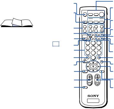

 Remote Control
In the instructions that follow, we will refer to the buttons on your remote control. Keep this flap unfolded and use this page for reference.
SLEEP
PICTURE MODE (pages 16, 22)
CC (page 18)
0 – 9 buttons
(page 16) JUMP (page 17)
 (pages 18, 23)/ INDEX (for SAT, page 45)
RESET
(pages 19, 22, 23)
VOL +/– (page 16)
CODE SET
(pages 43, 45)
MUTING |
DVD/ |
SAT/ |
POWER |
|
VTR |
CABLE |
|
|
|
|
TV |
SYSTEM |
|
FUNCTION |
|
OFF |
DVD/VTR SAT/CABLE |
TV |
|
TV/VTR |
FREEZE |
SWAP |
PIP |
|
m |
N |
M |
|
POSITION AUDIO |
ACTIVE |
|
X |
z |
x |
|
|
SLEEP |
ANT |
TV/VIDEO |
PICTURE |
CC |
MTS/SAP |
DISPLAY |
MODE |
|||
1 |
2 |
3 |
4 |
5 |
6 |
7 |
8 |
9 |
JUMP |
0 |
ENTER |
|
|
|
INDEX |
|
GUIDE |
RESET |
|
MENU |
VOL |
|
CH |
CODE SET
TV
POWER
(pages 16, 44, 45)
FUNCTION
(pages 16, 44, 45)
PIP operation buttons
(page 19)
TV/VIDEO
(pages 17, 19)
ANT (page 20)
DISPLAY
(page 17)
MTS/SAP
(pages 18, 23) ENTER (page 16)
GUIDE (page 45)
V/v/B/band
 buttons
(page 21) MENU (page 21)
CH +/– (page 16)
Getting to know the buttons on the remote control
Names of the buttons on the remote control are presented in different colors to represent the available functions.
Button color |
|
Transparent .... |
Press to select the component |
|
you want to control; e.g. VTR |
|
(VCR)/MDP/DVD Player, |
|
SAT (satellite receiver)/ |
|
CABLE, or projection TV. |
Green ............... |
Buttons relevant to power |
|
operations, like turning the |
|
projection TV, SAT/CABLE, or |
|
VTR (VCR)/MDP/DVD Player |
|
on or off |
Label color |
|
White ............... |
TV/VTR (VCR)/MDP/DVD |
|
Player/SAT (satellite |
|
receiver)/CABLE operation |
|
buttons |
Yellow .............. |
PIP operation buttons |
Blue .................. |
SAT operation buttons |
Green ............... |
S-Link operation buttons |
Pink .................. |
DVD Player operation buttons |
For a detailed explanation of most buttons, see “Watching the TV” on page 16.
Table of Contents |
|
Welcome! ........................................ |
1 |
Using This Manual .......................... |
1 |
Precautions...................................... |
2 |
Installing and Connecting the |
|
Projection TV....................... |
3 |
Carrying Your Projection TV ...................... |
3 |
Installing the Projection TV ........................ |
3 |
Connector Types .......................................... |
4 |
Making Connections ................................... |
4 |
Connecting directly to a cable or an |
|
antenna ............................................... |
4 |
Cable or antenna .................................... |
5 |
Cable and antenna ................................. |
5 |
Connecting a cable box ......................... |
5 |
Cable box and cable .............................. |
5 |
Connecting a cable TV system/ |
|
antenna to a VCR .............................. |
6 |
Connecting a VCR and projection TV |
|
to a cable box ..................................... |
6 |
Connecting a satellite receiver (SAT) .. |
7 |
Connecting a satellite receiver (SAT) |
|
and a VCR .......................................... |
8 |
Connecting a DTV (digital television) |
|
receiver ............................................... |
9 |
Connecting a camcorder ....................... |
9 |
Connecting two VCRs for tape |
|
editing ............................................... |
10 |
Connecting a DVD Player .................. |
11 |
Connecting a DVD Player with |
|
component video output |
|
connectors ........................................ |
11 |
Connecting an audio system ............. |
12 |
Connecting a Sony SAVA series |
|
speaker system ................................ |
13 |
Basic Set Up................................... |
14 |
Using the Remote Control ........................ |
14 |
Setting Up the Projection TV |
|
Automatically ................................... |
14 |
Adjusting the Convergence Automatically |
|
(FLASH FOCUS) .............................. |
15 |
Using Your New Projection TV .... |
16 |
Watching the TV ........................................ |
16 |
Watching Two Programs at One Time |
|
— PIP ................................................. |
19 |
Adjusting Your SET UP (menus) ... 21
Learning Menu Selection .......................... |
21 |
Using the Video Menu ......................... |
22 |
Using the Audio Menu ........................ |
23 |
Using the Timer Menu ........................ |
25 |
ch Using the Channel Set Up Menu ...... |
26 |
Setting and Selecting Favorite Channel.. |
28 |
Using the Set Up Menu ...................... |
30 |
Using the Parental Control Feature......... |
32 |
Activating the Parental Control |
|
Feature .............................................. |
32 |
Selecting a Custom Rating |
|
in U.S.A............................................. |
34 |
Selecting a Custom Rating |
|
in Canada ......................................... |
37 |
Changing the Password ..................... |
38 |
What the Ratings Mean ............................ |
39 |
Ratings in U.S.A................................... |
39 |
Ratings in Canada ............................... |
41 |
Open Here For Table of Contents and Remote Control Graphics
Operating Video Equipment ........... |
43 |
Setting the Manufacturer's Code ................ |
43 |
Operating a Cable Box or Satellite |
|
Receiver (SAT) ...................... |
45 |
Setting the Manufacturer's Code ................ |
45 |
Troubleshooting .............................. |
46 |
Specifications ................................... |
48 |
Index .............................................. |
49 |
Owner’s Record
The model and serial numbers are located at the rear of the projection TV, below the Sony logo, on the sticker, and also on the TV box (white label). Record these numbers in the spaces provided below. Refer to them whenever you call upon your Sony dealer regarding this product.
Model No.
Serial No.
Welcome! |
Using This Manual |
Thank you for purchasing the Sony Color Rear Video Projection TV.
This manual is for models KP-43T70, KP46C70, KP-48S70, KP-48S72, KP-53S70, KP53N74 and KP-61S70.
Model KP-53S70 is used for illustration purposes.
The features you will enjoy include:
•FLASH FOCUS, allowing you to adjust convergence automatically.
•Parental Control, enabling you to block programs that you feel are unsuitable for your children.
•Picture-in-Picture (PIP), allowing you to view another TV channel, video or cable image as a window picture.
•Favorite Channel, allowing you to view and choose from eight of your favorite channels
•Y/PB/PR inputs for DVD Player and DTV receiver connections.
•Three AUDIO/VIDEO/S VIDEO inputs.
We recommend that you carefully review the contents of the following four sections in the order provided to ensure that you fully understand the operation of your new projection TV.
1Installing and Connecting the Projection TV
This section guides you through your initial set up. It shows you how to install your projection TV, to connect your new components and to connect to the antenna and cable.
2Basic Set Up
This section teaches you the basic skills needed to operate your new projection TV, including Auto Set Up. It shows you how to operate the remote control’s special functions.
3Using Your New Projection TV
This section shows you how to begin using your new projection TV. It shows you how to use your remote control’s features.
4Adjusting Your Set Up (menus)
This section teaches you how to access on-screen menus and adjust your projection TV’s settings.
Instructions in this manual are written for the remote control. Similar controls may be found on the projection TV console.
1


 PrecautionsInstalling and Connecting the Projection TV (continued)
Safety
•Operate the projection TV only on 120 V AC.
•The plug is designed, for safety purposes, to fit into the wall outlet only one way. If you are unable to insert the plug fully into the outlet, contact your dealer.
•If any liquid or solid object should fall inside the cabinet, unplug the projection TV immediately and have it checked by qualified service personnel before operating it further.
•If you will not be using the projection TV for several days, disconnect the power by pulling the plug itself. Never pull on the cord.
For details concerning safety precautions, see the supplied leaflet “IMPORTANT SAFEGUARDS.”
Note on cleaning
Clean the cabinet of the projection TV with a dry soft cloth. To remove dust from the screen, wipe it gently with a soft cloth. Stubborn stains may be removed with a cloth slightly dampened with solution of mild soap and warm water. Never use strong solvents such as thinner or benzine for cleaning.
If the picture becomes dark after using the projection TV for a long period of time, it may be necessary to clean the inside of the projection TV. Consult qualified service personnel.
Installing
•To prevent internal heat buildup, do not block the ventilation openings.
•Do not install the projection TV in a hot or humid place, or in a place subject to excessive dust or mechanical vibration.
•Avoid operating the projection TV at temperatures below 5° C (41° F).
•If the projection TV is transported directly from a cold to a warm location, or if the room temperature changes suddenly, the picture may be blurred or show poor color. In this case, please wait a few hours to let the moisture evaporate before turning on the projection TV.
•To obtain the best picture, do not expose the screen to direct illumination or direct sunlight. It is recommended to use spot lighting directed down from the ceiling or to cover the windows that face the screen with opaque drapery. It is desirable to install the projection TV in a room where the floor and walls are not of a reflective material.
2

 Installing and Connecting the Projection TV
Carrying Your Projection TV
Carrying the projection TV requires three or more people.
For KP-46C70/48S70/48S72/53S70/ 53N74/61S70
The projection TV has been equipped with casters for easy movement on a hard surface. Please move your projection TV using the casters.
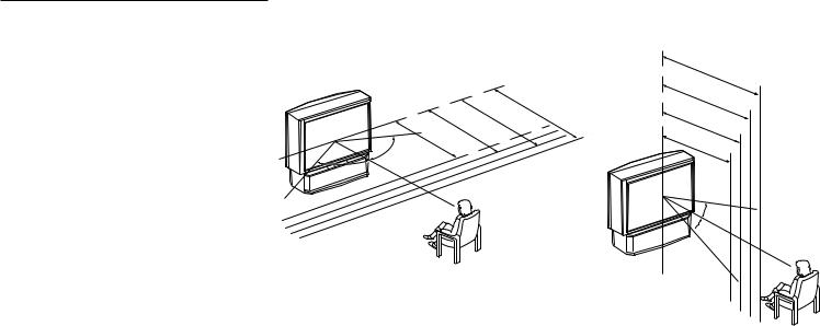
Installing the Projection TV |
Recommended viewing area |
|
(Vertical) |
||
|
Recommended viewing area (Horizontal)
|
|
|
|
|
|
|
|
|
min. |
|
|
|
|
|
|
|
|
|
|
|
min. |
|
2. |
|
|
|
|
|
|
|
|
|
. |
|
4m |
(approx. |
|
||||
|
|
|
min. |
|
2. |
|
|
|
|||||
|
|
|
|
|
|
1m |
|
61" |
|
|
|||
|
. |
|
1 |
|
|
|
|
|
) |
||||
min. |
|
|
|
8m |
|
|
(approx. |
|
8 |
||||
1 |
|
|
|
|
|
|
53" |
|
) |
|
ft. |
||
|
|
5m |
|
|
|
|
(approx. |
|
|
|
|
||
|
|
|
|
|
46", |
48" |
|
|
7 ft. |
|
|
||
|
|
|
(approx. |
6 |
) |
|
|
|
|
||||
|
|
43" |
|
|
|
|
ft. |
|
|
|
|
||
60° |
|
|
|
5 |
ft.) |
|
|
|
|
|
|||
|
|
|
|
|
|
|
|
|
|
|
|
||
60°
min. 2. |
|
|
|
|
|
4m |
(approx |
|
|
|
|
|
||
|
61" |
. 8ft |
||
min. 2. |
|
|
.) |
|
|
|
|
||
|
1m |
(approx |
|
|
|
|
|
||
|
53" |
. 7ft |
||
min. 1. |
|
|
.) |
|
|
8m |
|
|
|
min |
46",(approx. |
6ft |
||
|
48" |
|
||
. 1. |
|
|
.) |
|
|
5m |
(approx |
|
|
|
|
|
||
|
43" |
. 5ft |
||
|
|
|
|
.) |
|
|
20° |
|
|

 20°
20°
3

 Installing and Connecting the Projection TV (continued)
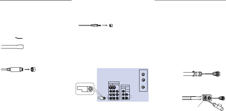
Connector Types
You may find it necessary to use some of the following connector types during set up.
Coaxial cable
Standard TV cable and antenna cable
Plug Type


 Push into connection.
Screw-on Type


 Screw into connection.
S Video cable
High quality video cable for enhanced picture quality
Align guides and push into connection.
Audio/Video cable


 Push into connection.
Video - Yellow Audio (Left) - White Audio (Right) - Red
Some DVD Players and DTV Receivers are equipped with the following three video connectors.
Y - Green
PB (CB, Cb or B–Y) - Blue 4 PR (CR, Cr or R–Y) - Red
CONTROL S cable
Sony cable for CONTROL S connection. This feature is exclusive to Sony products and allow greater control of all Sony equipment.
Push into connection.
About the CONTROL S OUT jack
To control other Sony equipment with the projection TV’s remote control, connect the CONTROL S IN jack of the equipment to the CONTROL S OUT jack on the projection TV with the CONTROL S cable.
(Rear of projection TV)
AUX
|
|
|
|
TO |
|
|
|
|
CONVERTER |
|
|
|
IN |
|
|
|
VIDEO 1 |
VIDEO 3 |
VHF/UHF |
|
|
|
|
|
|
|
|
OUT |
|
CONTROL S |
|
S VIDEO |
MONITOR |
AUDIO |
|
|
|
(VAR/FIX) |
|
OUT |
|
VIDEO |
Y |
VIDEO |
|
|
|||
|
|
L |
PB |
L |
|
|
(MONO) |
(MONO) |
|
|
|
AUDIO |
|
AUDIO |
|
CONTROL S |
R |
PR |
R |
|
OUT |
|||
|
|
|
|
|
|
|
|
COMPONENT |
|
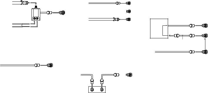
Making Connections
Connecting directly to a cable or an antenna
The connection you choose will depend on the cable found in your home. Newer homes will be equipped with standard coaxial cable (see A); older homes will probably have 300ohm twin lead cable (see B); still other homes may contain both (see C ).
Use 75-ohm coaxial cable for improved picture quality (see A).
A |
|
75-ohm |
(Rear of |
|
• VHF only |
projection TV) |
|
|
coaxial cable |
||
|
or |
VHF/UHF |
|
|
|
|
|
|
• VHF/UHF |
|
|
|
or |
|
|
|
• Cable |
|
|
B |
|
|
(Rear of |
|
• VHF only |
300-ohm twin |
projection TV) |
|
VHF/UHF |
||
|
lead cable |
||
|
or |
|
|
|
|
|
|
|
• UHF only |
|
|
|
or |
|
|
|
• VHF/UHF |
Antenna connector |
|
|
|
||
C |
|
75-ohm coaxial cable |
|
• VHF |
(Rear of |
|
projection TV) |
|
|
|
|
|
|
VHF/UHF |
|
and |
|
|
|
EAC-66 U/V mixer |
|
|
(not supplied) |
|
• UHF |
|
|
|
300-ohm twin lead cable |
Cable or antenna
This is the simplest connection. Connection is made directly from the cable or antenna to the projection TV.
|
(Rear of projection TV) |
Coaxial cable |
VHF/UHF |
|
Cable and antenna
You may find it convenient to use the following set up if your cable provider does not feature local channels that you are able to receive using an antenna.
|
(Rear of projection TV) |
Coaxial cable |
AUX |
|
|
(No connection “TO |
TO CONVERTER |
CONVERTER” in this case) |
|
Antenna cable |
VHF/UHF |
Select Cable or ANT mode by pressing ANT on the remote control.
Connecting a cable box
Some pay cable TV systems use scrambled or encoded signals that require a cable box* to view all channels.
Also, set “Cable” to “On” in the Channel Set Up menu (page 27).
|
(Rear of projection TV) |
||
Coaxial cable |
|
VHF/UHF |
|
|
|
|
|
IN |
OUT |
*Cable box
Cable box and cable
Some pay cable TV systems use scrambled or encoded signals requiring a cable box* only for certain channels (e.g. HBO, SHOWTIME, etc.)
*Cable box |
(Rear of projection TV) |
|
|
||
|
|
AUX |
Scrambled |
|
TO CONVERTER |
channels |
|
|
|
|
|
|
75-ohm coaxial cable |
(Signal) |
|
(not supplied) |
|
|
VHF/UHF |
|
CATV cable (unscrambled channels)
For this set up, you can switch between scrambled channels (through your cable box), and normal (CATV) channels by pressing ANT on your remote control.
Notes:
•You may be able to program your Sony remote control to operate your cable box. (see “Operating a Cable Box or Satellite Receiver (SAT)” on page 45)
•During PIP or Favorite Channel viewing, the AUX input can only be viewed in the main picture.
5


 Installing and Connecting the Projection TV (continued)
Disconnect all power sources before making any connections.
Connecting a cable TV system/ |
(Rear of projection TV) |
|
antenna to a VCR |
||
|
1 Attach the coaxial cable from the |
|
|
|
AUX |
|
|
|
|
|
|
|
|
|
|
|
|
|
|
|
|
|
||
|
incoming cable connection or antenna to |
|
|
|
TO |
|
|
|
|
|
|
|
|
|
|
CONVERTER |
|
|
|
|
|
|
|
|
|
|
|
|
|
|
Coaxial cable |
|
|
||
|
VHF/UHF IN on the VCR. |
|
|
|
|
|
|
|
|
||
|
|
IN |
|
|
2 |
|
|
|
|
|
|
2 |
|
VIDEO 1 |
VIDEO 3 |
|
VHF/UHF |
|
|
|
|
|
|
Using a coaxial cable, connect VHF/UHF |
|
OUT |
|
|
|
|
|
||||
|
|
|
|
|
|
|
|||||
S VIDEO |
MONITOR |
AUDIO |
|
|
|
|
|
|
|
||
|
(VAR/FIX) |
|
|
|
|
|
|
|
|||
|
OUT on the VCR to VHF/UHF on the |
VIDEO |
Y |
|
VIDEO |
|
AUDIO R AUDIO L VIDEO |
S VIDEO |
VCR |
|
|
|
projection TV. |
|
|
|
|
|
LINE |
|
|
|
|
|
L |
PB |
|
L |
|
IN |
|
VHF/UHF |
|
|
|
|
|
|
|
|
|
|
|
||||
|
(MONO) |
|
|
(MONO) |
|
|
|
OUT |
|
|
|
|
AUDIO |
|
|
AUDIO |
|
LINE |
|
|
Cable/ |
||
3 |
|
|
|
|
|
IN |
|
||||
Using AUDIO and S VIDEO* cables, |
R |
PR |
|
R |
|
OUT |
|
|
|||
|
|
|
|
|
1 |
||||||
|
COMPONENT |
|
|
|
|
|
|
Antenna |
|||
|
connect AUDIO and S VIDEO OUT on the |
|
VIDEO |
|
VMC-810S/820S |
|
|
|
|
||
|
S VIDEO |
|
|
|
|
|
|
|
|||
|
VCR to AUDIO and S VIDEO IN on the |
AUDIO-L |
(not supplied) |
|
|
|
|
|
|
||
|
|
AUDIO-R |
YC-15V/30V |
|
3 |
|
|
|
|||
|
projection TV (White-AUDIO Left, Red- |
|
|
|
|
|
|
|
|||
|
|
|
|
(not supplied) |
|
|
|
||||
|
AUDIO Right**). |
|
|
|
|
|
|
|
|
|
|
Connecting a VCR and projection TV to a cable box
1Connect the single (input) jack of the splitter to the incoming cable connection, and connect the other two (output) jacks (using the coaxial cable) to IN on the cable box and VHF/UHF on the projection TV.
2Using a coaxial cable, connect OUT on the cable box to VHF/UHF IN on the VCR.
3Using AUDIO and S VIDEO* cables, connect AUDIO and S VIDEO OUT on the VCR to AUDIO and S VIDEO IN on the
projection TV (White-AUDIO Left, Red- 6 AUDIO Right**).
(Rear of projection TV)
|
|
|
Coaxial cable |
|
|
1 |
||
|
|
|
AUX |
|
|
|
|
|
|
|
|
TO |
|
|
|
|
Cable/ |
|
|
|
CONVERTER |
|
|
|
|
Antenna |
|
|
|
|
|
|
|
|
|
|
IN |
|
|
|
Splitter (not supplied) |
|||
VIDEO 1 |
VIDEO 3 |
|
VHF/UHF |
|
|
|
|
|
|
OUT |
|
|
|
|
|
|
|
|
|
|
|
|
|
|
|
|
S VIDEO |
MONITOR AUDIO |
|
|
|
|
|
|
|
|
(VAR/FIX) |
|
|
|
|
|
|
VCR |
|
|
|
AUDIO R AUDIO L VIDEO |
S VIDEO |
|
|
||
VIDEO |
Y |
VIDEO |
LINE |
|
|
|
|
2 |
|
|
|
IN |
|
|
VHF/UHF |
||
L |
PB |
L |
|
|
|
OUT |
|
|
(MONO) |
(MONO) |
LINE |
|
|
IN |
|
||
AUDIO |
|
AUDIO |
OUT |
|
|
|
|
|
R |
PR |
R |
|
|
|
|
|
|
|
COMPONENT |
|
|
|
|
|
|
|
|
VIDEO |
VMC-810S/820S |
|
|
|
OUT |
||
S VIDEO |
|
|
|
|
IN |
|||
AUDIO-L |
(not supplied) |
|
Cable box |
|||||
|
AUDIO-R |
|
YC-15V/30V |
3 |
||||
|
|
|
|
|
|
|
||
|
|
|
(not supplied) |
|
|
|
|
|
Note:
•To view scrambled channels through the cable box, select the video input which the cable box is connected to by pressing TV/ VIDEO.
*If your VCR is not equipped with S VIDEO, use a VIDEO cable (yellow) instead of the S VIDEO cable.
**If you are connecting a monaural VCR, connect only the single audio output to the left (MONO) input on the projection TV.
Connecting a satellite receiver (SAT)
1Connect the cable from the satellite antenna to the satellite receiver.
2Attach the coaxial cable from the incoming cable connection or antenna to VHF/UHF on the projection TV.
3Using AUDIO and S VIDEO cables, connect AUDIO and S VIDEO OUT on the satellite receiver to AUDIO and S VIDEO IN on the projection TV (White-AUDIO Left, Red-AUDIO Right).
Note:
•To view input from the satellite receiver, select the video input which the satellite receiver is connected to by pressing TV/ VIDEO on the remote control.
Disconnect all power sources before making any connections.
(Rear of projection TV)
Cable/ AUX Antenna
|
|
TO |
2 |
|
|
CONVERTER |
|
|
IN |
|
|
VIDEO 1 |
VIDEO 3 |
VHF/UHF |
|
|
OUT |
|
|
|
|
|
|
S VIDEO |
MONITOR AUDIO |
|
|
|
(VAR/FIX) |
|
|
VIDEO |
Y |
VIDEO |
|
L |
PB |
L |
|
(MONO) |
|
(MONO) |
|
AUDIO |
|
AUDIO |
|
R |
PR |
R |
|
|
COMPONENT |
|
|
|
S VIDEO |
|
|
|
AUDIO-L |
|
|
|
AUDIO-R |
RK-74A (not supplied) |
|
|
|
||
Satellite antenna cable
1
SAT
SATELLITE IN
VHF/UHF
AUDIO R AUDIO L VIDEO S VIDEO |
IN |
 OUT
OUT
LINE OUT
 3
3 
YC-15V/30V (not supplied)
7

 Installing and Connecting the Projection TV (continued)
Disconnect all power sources before making any connections.
Connecting a satellite receiver (SAT) and a VCR
1 |
Connect the cable from the satellite |
(Rear of projection TV) |
|
2 |
antenna to the satellite receiver. |
3 |
Coaxial cable |
Attach the coaxial cable from the |
AUX |
|
|
|
SAT |
||
|
incoming cable connection or antenna to |
CONVERTER |
|
|
SATELLITE IN |
||
|
VHF/UHF IN on the VCR. |
TO |
|
|
|
VHF/UHF |
3 Using a coaxial cable, connect VHF/UHF |
|
IN |
|
|
AUDIO R AUDIO L VIDEO |
S VIDEO |
OUT |
|
|
|
|
LINE |
|
|
|||
VIDEO 1 |
OUT |
|
|
|
IN |
|||
|
OUT |
|
|
|||||
|
VIDEO 3 |
|
VHF/UHF |
|
|
|||
OUT on the VCR to VHF/UHF on the |
S VIDEO |
MONITOR |
AUDIO |
1 |
|
|
|
|
VIDEO |
Y |
VIDEO |
|
|
|
|
||
|
|
|
(VAR/FIX) |
|
|
|
|
|
projection TV. |
|
PB |
|
Satellite |
|
|
|
|
|
(MONO) |
(MONO) |
|
|
|
|||
4 Using AUDIO and S VIDEO* cables, |
L |
|
L |
|
|
|
|
|
|
|
antenna |
|
|
|
|||
R |
PR |
R |
|
|
|
|||
|
AUDIO |
|
AUDIO |
|
|
|
|
|
connect AUDIO and S VIDEO OUT on the |
|
|
|
cable |
|
|
|
YC-15V/ |
|
COMPONENT |
|
|
4 |
|
30V |
||
|
|
VMC-810S/ |
|
|||||
satellite receiver to AUDIO and S VIDEO |
|
VIDEO |
|
|
(not |
|||
|
|
820S (not |
|
|
||||
IN on the VCR. |
S VIDEO |
AUDIO-L |
|
|
|
supplied) |
||
|
supplied) |
|
|
|||||
|
|
|
|
|||||
5 Using AUDIO and S VIDEO* cables, |
|
AUDIO-R |
|
|
|
|
|
|
|
|
|
|
|
|
|
|
|
connect AUDIO and S VIDEO OUT on the |
|
|
|
|
AUDIO R AUDIO L VIDEO |
S VIDEO |
|
|
|
|
|
|
LINE |
|
|
|
|
VCR to AUDIO and S VIDEO IN on the |
|
|
|
|
IN |
|
|
VHF/UHF |
|
|
|
|
LINE |
|
|
OUT |
|
projection TV (White-AUDIO Left, Red- |
5 |
|
|
VCR |
OUT |
|
|
IN |
|
|
|
|
|
|
2 |
||
AUDIO Right). |
|
VMC-810S/820S (not supplied) |
|
|
|
|||
* If your VCR is not equipped with S VIDEO, use a |
|
|
|
|
|
|||
|
|
|
|
|
|
|
|
|
VIDEO cable (yellow) instead of the S VIDEO |
|
|
|
|
|
|
|
Cable/ |
cable. |
|
|
|
|
|
|
|
|
|
|
|
|
|
|
|
Antenna |
|
Note: |
|
YC-15V/30V (not supplied) |
|
|
|
|
||
|
|
|
|
|
|
|||
•To view input from the satellite receiver or VCR, select the video input which your satellite receiver or VCR is connected to by pressing TV/VIDEO on the remote control.
8

Connecting a DTV (digital television) receiver |
|
|
Disconnect all power sources before making any connections. |
|||||||||
|
|
|
|
|
|
|
|
2 |
|
|
||
Before connecting, be sure to read the |
|
|
|
|
|
|
|
|
|
|
|
|
Operating Instructions of the DTV receiver. |
|
|
|
VMC-10HG (not supplied) |
|
|
|
|
|
|
||
1 Attach the coaxial cable from the roof |
|
|
|
|
|
|
|
|
|
|||
|
Y |
|
AUX |
|
|
|
|
|
|
|
|
|
antenna to VHF/UHF on the DTV |
|
|
|
|
|
|
|
|
|
|
|
|
|
PB |
|
TO |
|
|
|
|
|
|
|
|
|
receiver. |
|
PR |
|
CONVERTER |
DTV receiver |
|
|
|
|
|
|
|
2 Using three yellow VIDEO cables, |
|
|
|
|
|
|
|
|
|
|
|
|
|
IN |
|
|
|
|
|
|
|
|
|
|
|
connect Y, PB and PR of VIDEO OUT on |
VIDEO 1 |
VIDEO 3 |
|
VHF/UHF |
|
|
|
|
|
|
|
|
|
|
OUT |
|
|
S VIDEO |
|
|
|
|
|
||
the DTV receiver to Y, PB and PR of |
|
|
|
(DTV) |
|
|
|
|
|
|
||
S VIDEO |
|
MONITOR AUDIO |
|
|
|
|
|
|
|
|
||
|
|
|
(VAR/FIX) |
|
VHF/UHF |
|
|
|
|
|
|
|
VIDEO 3 IN on the projection TV. |
|
|
|
|
|
AUDIO OUT |
VIDEO |
|
|
|
|
|
VIDEO |
Y |
VIDEO |
|
|
1 |
2 |
|
Y |
R |
|
||
|
|
|
|
|
|
DOLBY DIGITAL |
|
|
||||
3 Using an AUDIO cable, connect AUDIO |
L |
|
L |
|
IN |
(OPTICAL) |
L |
|
|
|
|
|
PB |
AUDIO |
|
|
CONVERTER |
(MONO) |
|
|
PB |
G |
HD |
||
AUDIO |
|
|
|
|
|
|
||||||
|
(MONO) |
|
(MONO) |
|
|
DOWN |
|
|
|
|||
|
|
|
|
|
|
|
|
|
|
|
|
|
OUT on the DTV receiver to AUDIO of |
|
|
|
|
CONTROL S |
ON/OFF |
R |
|
|
VIDEO OUT |
|
|
|
|
|
|
|
AUDIO OUT |
|
|
|
||||
|
R |
PR |
R |
|
OUT |
|
1 |
2 |
3 |
PR 4 |
B |
VD |
|
|
|
|
|||||||||
VIDEO 3 IN on the projection TV (White- |
|
|
|
|
|
|
||||||
|
COMPONENT |
|
|
|
|
|
|
|
|
|
|
|
AUDIO Left, Red-AUDIO Right). |
|
|
(Rear of projection TV) |
|
|
|
|
|
|
|
|
|
|
|
|
|
1 |
4 |
|
|
|
|
|
|
|
4 Set the DOWN CONVERTER ON/OFF |
AUDIO-L |
AUDIO-R |
|
|
|
|
|
|
|
|||
switch on the DTV receiver to ON. |
|
|
RK-74A (not supplied) |
Roof antenna |
|
3 |
|
|
|
|
|
|
Connecting a camcorder |
|
|
|
|
|
|
|
|
|
|
|
|
|
|
|
|
|
|
|
|
|
|
|
|
|
Use this connection to view a picture directly from your camcorder.
1Using AUDIO and S VIDEO* cables, connect AUDIO and S VIDEO OUT on the camcorder to AUDIO and S VIDEO IN inside the drop-down panel on the front of the projection TV (White-AUDIO Left, Red-AUDIO Right**).
2Press VIDEO 2 to select the video inputs from a camcorder.
*If your camcorder is not equipped with S VIDEO, use a VIDEO cable (yellow) instead of the S VIDEO cable.
**If you are connecting a monaural camcorder, connect only the single audio output to the left (MONO) input on the projection TV.
YC-15V/30V (not supplied)
|
|
|
Audio/ |
|
|
VMC-810S/820S |
video |
|
|
outputs |
|
|
|
(not supplied) |
S VIDEO |
|
|
VIDEO |
|
S VIDEO |
|
OUT |
|
|
AUDIO-L |
||
|
|
AUDIO-R |
|
S VIDEO |
VIDEO |
L AUDIO R |
|
|
(MONO) |
|
|
|
VIDEO 2 INPUT |
|
|
(Front of projection TV) |
Camcorder |
9 |
|
||
|
|

 Installing and Connecting the Projection TV (continued)
Disconnect all power sources before making any connections.
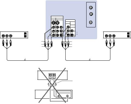
Connecting two VCRs for tape editing
By connecting a second VCR to MONITOR OUT, you can record a program being played by the primary VCR to the second VCR or perform tape editing and dubbing.
(Rear of projection TV)
AUX
TO
CONVERTER
1 Connect the VCR intended for playback |
|
|
|
|
VIDEO 1 |
VIDEO 3 |
|
|
|
|
|
|
|
|
|
IN |
|
|
|
using the connection instructions on page |
|
|
|
|
|
|
VHF/UHF |
|
|
|
|
|
|
|
|
OUT |
|
|
|
|
|
|
S VIDEO |
|
|
MONITOR AUDIO |
|
|
|
6 of this manual. |
|
|
|
|
|
|
(VAR/FIX) |
|
|
VCR (for playback) |
VIDEO |
|
Y |
VIDEO |
VCR (for recording) |
||||
2 Using an AUDIO/VIDEO cable, connect |
L |
|
PB |
L |
|||||
AUDIO R AUDIO L VIDEO |
|
OUT |
|
AUDIO |
AUDIO R AUDIO L VIDEO |
OUT |
|||
|
AUDIO |
|
|
||||||
AUDIO and VIDEO IN on the VCR |
|
|
|
(MONO) |
|
|
(MONO) |
|
|
|
LINE |
IN |
R |
|
PR |
R |
LINE |
IN |
|
|
|
OUT |
|
|
|
|
IN |
||
intended for recording to AUDIO and |
|
|
|
|
|
COMPONENT |
|
|
|
|
|
|
VIDEO |
|
|
VIDEO |
|
|
|
VIDEO OUT of MONITOR OUT on the |
|
|
|
AUDIO-L |
|
|
AUDIO-L |
|
|
projection TV. |
|
|
|
AUDIO-R |
|
|
AUDIO-R |
2 |
|
1 |
VMC-810S/820S |
|
|
VMC-810S/820S |
|
||||
Notes: |
|
|
|
||||||
|
(not supplied) |
|
|
(not supplied) |
|
|
|||
• Do not change the input signal while |
|
|
|
|
|
|
|
|
|
editing through MONITOR OUT. |
|
|
|
(Rear of projectionTV) |
|
|
|||
• When connecting a single VCR to the |
|
|
|
|
|
||||
|
|
|
|
|
|
|
|
|
|
projection TV: if VCR LINE OUT is |
|
|
|
|
|
|
|
|
|
connected to VIDEO IN on the projection |
|
|
|
VIDEO IN |
|
MONITOR |
|
|
|
|
|
|
|
|
|
|
|||
TV, do not connect MONITOR OUT on |
|
|
|
|
|
OUT |
|
|
|
|
|
|
|
|
|
Indicates direction |
|
|
|
the projection TV to the VCR LINE |
|
|
|
|
|
|
|
|
|
|
|
|
|
|
|
of signal |
|
|
|
INPUT (see right). Doing so will cause |
|
|
|
VCR |
|
|
|
|
|
program interference and other viewing |
|
|
|
|
|
LINE |
|
|
|
problems. |
|
|
|
|
|
IN |
OUT |
|
|
|
|
|
|
|
|
|
|
|
|
10
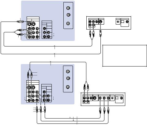
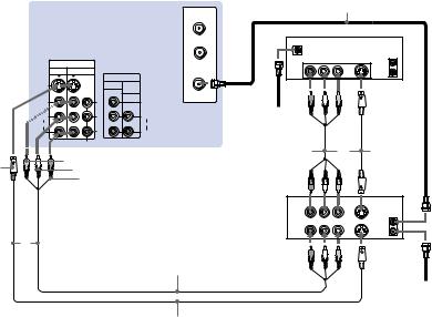
Connecting a DVD Player (Upper illustration)
Using an AUDIO and S VIDEO cables, connect AUDIO and S VIDEO IN on the projection TV to AUDIO and S VIDEO OUT on the DVD Player (White-AUDIO Left, RedAUDIO Right).
Connecting a DVD Player with component video output connectors (Lower illustration)
1Using an AUDIO cable, connect AUDIO of LINE OUT on the DVD Player to AUDIO of VIDEO 3 IN on the projection TV (WhiteAUDIO Left, Red-AUDIO Right).
2Using three yellow VIDEO cables, connect Y, PB, and PR of COMPONENT VIDEO OUT on the DVD Player to Y, PB, and PR of VIDEO 3 IN on the projection TV.
Notes:
•Since the high quality pictures on a DVD disc contain a lot of information, picture noise may appear. In this case, adjust “Noise Reduction” in the Video menu. (see “Noise Reduction” on page 22)
•Some DVD Player terminals may be labeled differently. If so, connect as follows: Connect Y (green) to Y.
Connect PB (blue) to CB, Cb or B-Y. Connect PR (red) to CR, Cr or R-Y.
Disconnect all power sources before making any connections.
(Rear of projection TV)
|
|
AUX |
|
|
|
|
|
|
|
|
TO |
|
|
|
|
|
|
|
|
CONVERTER |
|
DVD |
|
|
|
|
S VIDEO |
|
|
|
|
|
|
||
IN |
|
|
|
|
|
|
||
|
LINE OUT |
S VIDEO OUT |
S-LINK |
DIGITAL OUT |
||||
VIDEO 1 |
VIDEO 3 |
|||||||
R–AUDIO 1–L |
VIDEO |
|
|
OPTICAL |
COAXIAL |
|||
|
|
VHF/UHF |
|
|
|
|
|
|
|
|
OUT |
|
|
|
|
|
|
S VIDEO |
|
MONITOR AUDIO |
|
|
|
|
|
|
|
|
(VAR/FIX) |
|
|
|
|
|
|
VIDEO |
Y |
VIDEO |
|
Audio/S video |
|
|||
(MONO) |
|
(MONO) |
|
|
||||
L |
PB |
L |
|
|
|
|
|
|
|
|
|
|
|
|
|||
AUDIO |
|
AUDIO |
|
outputs |
|
|
|
|
R |
PR |
R |
|
|
|
|
||
AUDIO-R |
COMPONENT |
|
|
|
|
|
|
|
AUDIO-L |
|
|
|
|
|
|
|
|
RK-74A (not supplied)
YC-15V/30V (not supplied)
(Rear of |
RK-74A (not supplied) |
|
|
projection |
AUX |
||
|
|||
TV) |
AUDIO-L |
TO |
|
|
AUDIO-R |
CONVERTER |
Connect the DVD Player directly to the projection TV. Connecting the DVD Player through other video equipment will cause unwanted picture noise.
|
IN |
|
|
VIDEO 1 |
VIDEO 3 |
|
|
|
OUT |
||
S VIDEO |
MONITOR |
AUDIO |
|
|
|
(VAR/FIX) |
|
VIDEO |
Y |
VIDEO |
|
L |
PB |
L |
|
(MONO) |
|||
(MONO) |
|
||
AUDIO |
|
AUDIO |
|
R |
PR |
R |
|
|
COMPONENT |
|
|
PR
PB
Y
VHF/UHF
|
|
|
DVD |
|
|
|
|
|
LINE OUT |
S VIDEO OUT |
COMPONENT VIDEO OUT |
S-LINK |
DIGITAL OUT |
||||
R–AUDIO 1–L |
VIDEO |
|
Y |
B-Y |
R-Y |
|
OPTICAL |
COAXIAL |
VMC-10HG (not supplied)
11

 Installing and Connecting the Projection TV (continued)
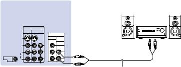
Connecting an audio system |
Disconnect all power sources before making any connections. |
|
|
For more dynamic sound, connect an audio |
(Rear of projection TV) |
system to the projection TV. |
|
1Using an AUDIO cable, connect AUDIO (VAR/FIX) OUT on the projection TV to one of the unused Line inputs (e.g. Tape- 2, AUX1, etc.) on the stereo.
2Set the stereo to the chosen Line input and use the Audio menu to set the audio output and switch the TV’s speakers off. (see “Audio Out” and “Speaker” on page 24)
Note:
•You can adjust VOLUME, “Bass,” “Treble,” “Balance,” “MTS/SAP” and “Effect” with the supplied remote control. The control items except VOLUME can be adjusted only when “Audio Out” is set to “Variable” in the Audio menu. (see “Audio Out” on page 24)
Stereo amplifier
|
|
IN |
|
|
|
|
VIDEO 1 |
VIDEO 3 |
|
|
|
|
|
|
OUT |
|
|
|
S VIDEO |
|
MONITOR AUDIO |
|
HRD |
|
|
|
|
||
|
|
|
(VAR/FIX) |
|
|
|
VIDEO |
Y |
VIDEO |
AUDIO-L |
|
|
(MONO) |
PB |
(MONO) |
(white) |
|
|
L |
|
L |
|
|
|
|
|
|
|
|
|
AUDIO |
PR |
AUDIO |
|
Line inputs |
CONTROL S |
R |
R |
|
||
OUT |
|
|
|
|
|
|
|
COMPONENT |
|
|
|
|
|
|
|
AUDIO-R |
RK-74A |
|
|
|
|
(red) |
(not supplied) |
12

Connecting a Sony SAVA series speaker system
Use this connection to control the speaker’s Dolby* Pro Logic surround system and super woofer mode with the remote control. (see “SAVA SP Control” on page 24)
1Using the AUDIO cable supplied with the speaker to AUDIO (VAR/FIX) OUT on the projection TV.
2Using the CONTROL S cable, connect CONTROL S IN on the speaker to CONTROL S OUT on the projection TV.
*Manufactured under license from Dolby Laboratories Licensing Corporation. Additionally licensed under Canadian patent
number 1,037,877. “Dolby,” the double-D symbol aand “Pro Logic” are trademarks of Dolby Laboratories Licensing Corporation.
Disconnect all power sources before making any connections.
(Rear of projection TV)
SAVA series speaker system
|
|
IN |
|
|
|
|
|
|
VIDEO 1 VIDEO 3 |
|
|
|
|
|
|
OUT |
AUDIO-L |
|
|
|
|
S VIDEO |
MONITOR AUDIO |
|
|
||
|
|
(VAR/FIX) |
(white) |
|
|
|
|
VIDEO |
|
|
1 IN L |
||
|
Y |
VIDEO |
1 |
|||
|
L |
PB |
L |
|
|
|
|
(MONO) |
(MONO) |
|
|
||
|
AUDIO |
|
AUDIO |
|
|
|
CONTROL S |
R |
PR |
R |
|
|
|
OUT |
|
1 IN R |
||||
|
|
|
|
|||
|
|
COMPONENT |
|
|
||
CONTROL S |
|
AUDIO-R (red) |
Audio cord supplied |
|||
OUT |
|
RK-G34, etc. (not supplied) |
with the speakers |
2 |
||
|
|
|
|
|
|
|
CONTROL S IN
13
 Loading...