


4-075-035-12 (1)
Trinitronâ Color
Graphic Display
Operating Instructions |
|
|
|
GB |
|||||
|
|
|
|
|
|
|
|
|
|
Mode d’emploi |
|
|
|
|
|
|
|
|
FR |
|
|
|
|
|
|||||
Bedienungsanleitung |
|
|
|
|
DE |
||||
|
|
|
|
||||||
Manual de instrucciones |
|
|
ES |
||||||
|
|
|
|
|
|||||
Istruzioni per l’uso |
|
|
|
|
|
|
IT |
||
|
|
|
|||||||
Инструкция по эксплуатации |
|
RU |
|||||||
|
|
|
|
||||||
Bruksanvisning |
|
|
|
|
|
|
|
SE |
|
|
|
|
|||||||
Gebruiksaanwijzing |
|
|
|
|
|
NL |
|||
GDM-F500R
© 1999 Sony Corporation
Owner’s Record
The model and serial numbers are located at the rear of the unit. Record these numbers in the spaces provided below. Refer to them whenever you call upon your dealer regarding this product. Model No. Serial No.
WARNING
To prevent fire or shock hazard, do not expose the unit to rain or moisture.
Dangerously high voltages are present inside the unit. Do not open the cabinet. Refer servicing to qualified personnel only.
FCC Notice
This equipment has been tested and found to comply with the limits for a Class B digital device, pursuant to Part 15 of the FCC Rules. These limits are designed to provide reasonable protection against harmful interference in a residential installation. This equipment generates, uses, and can radiate radio frequency energy and, if not installed and used in accordance with the instructions, may cause harmful interference to radio communications. However, there is no guarantee that interference will not occur in a particular installation. If this equipment does cause harmful interference to radio or television reception, which can be determined by turning the equipment off and on, the user is encouraged to try to correct the interference by one or more of the following measures:
–Reorient or relocate the receiving antenna.
–Increase the separation between the equipment and receiver.
–Connect the equipment into an outlet on a circuit different from that to which the receiver is connected.
–Consult the dealer or an experienced radio/TV technician for help. You are cautioned that any changes or modifications not expressly approved in this manual could void your authority to operate this equipment.
EN 55022 Compliance (Czech Republic Only)
This device belongs to category B devices as described in EN 55022, unless it is specifically stated that it is a category A device on the specification label. The following applies to devices in category A of EN 55022 (radius of protection up to 30 meters). The user of the device is obliged to take all steps necessary to remove sources of interference to telecommunication or other devices.
INFORMATION
This product complies with Swedish National Council for Metrology (MPR) standards issued in December 1990 (MPR II) for very low frequency (VLF) and extremely low frequency (ELF).
INFORMATION
Ce produit est conforme aux normes du Swedish National Council for Metrology de décembre 1990 (MPR II) en ce qui concerne les fréquences très basses (VLF) et extrêmement basses (ELF).
INFORMACIÓN
Este producto cumple las normas del Consejo Nacional Sueco para Metrología (MPR) emitidas en diciembre de 1990 (MPR II) para frecuencias muy bajas (VLF) y frecuencias extremadamente bajas (ELF).
NOTICE
This notice is applicable for USA/Canada only.
If shipped to USA/Canada, install only a UL LISTED/CSA LABELLED power supply cord meeting the following specifications:
SPECIFICATIONS |
|
|
|
|||||
Plug Type |
Nema-Plug 5-15p |
|||||||
Cord |
Type SVT or SJT, minimum 3 × 18 AWG |
|||||||
Length |
Maximum 15 feet |
|||||||
Rating |
Minimum 7 A, 125 V |
|||||||
|
|
|
|
|
|
|
|
|
|
|
|
|
|
|
|
|
|
|
|
|
|
|
|
|
|
|
|
|
|
|
|
|
|
|
|
|
|
|
|
|
|
|
|
|
|
|
|
|
|
|
|
|
|
|
|
|
|
|
|
|
|
|
|
|
|
|
|
|
|
|
|
|
|
|
|
|
|
|
|
|
Sony GDM-F500R
Sony Electronics Inc.
1 Sony Drive, Park Ridge, NJ. 07656 USA
201-930-6970
This device complies with Part 15 of the FCC Rules. Operation is subject to the following two conditions: (1) This device may not cause harmful interference, and (2) this device must accept any interference received, including interference that may cause undesired operation.
2
Table of Contents
Precautions. . . . . . . . . . . . . . . . . . . . . . . . . . . . . . . . . . . . . . . . . . . . 4
Identifying parts and controls . . . . . . . . . . . . . . . . . . . . . . . . . . . . . . 5
Setup . . . . . . . . . . . . . . . . . . . . . . . . . . . . . . . . . . . . . . . . . .6
Step 1: Connect your monitor to your computer . . . . . . . . . . . . . . . 6
Step 2: Connect the power cord. . . . . . . . . . . . . . . . . . . . . . . . . . . . 7
Step 3: Turn on the monitor and computer . . . . . . . . . . . . . . . . . . . 7
Connecting Universal Serial Bus (USB) compliant peripherals . . . . 8
Selecting the on-screen menu language (LANG) . . . . . . . . . . . . . . . 8
Selecting the input signal . . . . . . . . . . . . . . . . . . . . . . . . . . . . . . . . . 9
Automatically sizing and centering the picture (AUTO) . . . . . . . . . . 9
•Trinitron â is a registered trademark of Sony Corporation.
•Macintosh is a trademark licensed to Apple Computer, Inc., registered in the U.S.A. and other countries.
•Windows â and MS-DOS are registered trademarks of Microsoft Corporation in the United States and other countries.
•IBM PC/AT and VGA are registered trademarks of IBM Corporation of the U.S.A.
•VESA and DDC ä are trademarks of the Video Electronics Standard Association.
•ENERGY STAR is a U.S. registered mark.
•All other product names mentioned herein may be the trademarks or registered trademarks of their respective companies.
•Furthermore, “ ä” and “ â” are not mentioned in each case in this manual.
Customizing Your Monitor . . . . . . . . . . . . . . . . . . . . . . .10
Navigating the menu. . . . . . . . . . . . . . . . . . . . . . . . . . . . . . . . . . . . 10 Adjusting the brightness and contrast. . . . . . . . . . . . . . . . . . . . . . . 11 Adjusting the size of the picture (SIZE) . . . . . . . . . . . . . . . . . . . . . 11 Adjusting the centering of the picture (CENTER) . . . . . . . . . . . . . . 12 GB Enlarging or reducing the picture (ZOOM) . . . . . . . . . . . . . . . . . . . 12 Adjusting the shape of the picture (GEOM) . . . . . . . . . . . . . . . . . . 12 Adjusting the convergence (CONV) . . . . . . . . . . . . . . . . . . . . . . . . 12 Adjusting the quality of the picture (SCREEN) . . . . . . . . . . . . . . . . 13 Adjusting the color of the picture (COLOR) . . . . . . . . . . . . . . . . . . 13 Additional settings (OPTION) . . . . . . . . . . . . . . . . . . . . . . . . . . . . . 15 Resetting the adjustments . . . . . . . . . . . . . . . . . . . . . . . . . . . . . . . 16
Technical Features . . . . . . . . . . . . . . . . . . . . . . . . . . . . .16
Preset and user modes. . . . . . . . . . . . . . . . . . . . . . . . . . . . . . . . . . 16 Power saving function. . . . . . . . . . . . . . . . . . . . . . . . . . . . . . . . . . . 16
Troubleshooting. . . . . . . . . . . . . . . . . . . . . . . . . . . . . . . .17
If thin lines appear on your screen (damper wires). . . . . . . . . . . . . 17 On-screen messages . . . . . . . . . . . . . . . . . . . . . . . . . . . . . . . . . . . 17 Trouble symptoms and remedies . . . . . . . . . . . . . . . . . . . . . . . . . . 18 Self-diagnosis function . . . . . . . . . . . . . . . . . . . . . . . . . . . . . . . . . . 20
Specifications. . . . . . . . . . . . . . . . . . . . . . . . . . . . . . . . . .20
Appendix. . . . . . . . . . . . . . . . . . . . . . . . . . . . . . . . . . . . . . . i
Preset mode timing table . . . . . . . . . . . . . . . . . . . . . . . . . . . . . . . . . .i TCO’99 Eco-document . . . . . . . . . . . . . . . . . . . . . . . . . . . . . . . . . . . .i
3
Precautions
Warning on power connections
•Use the supplied power cord. If you use a different power cord, be sure that it is compatible with your local power supply.
For the customers in the UK
If you use the monitor in the UK, be sure to use the supplied UK power cable.
Example of plug types
for 100 to 120 V AC for 200 to 240 V AC for 240 V AC only
•Before disconnecting the power cord, wait at least 30 seconds after turning off the power to allow the static electricity on the screen’s surface to discharge.
•After the power is turned on, the screen is demagnetized (degaussed) for about 3 seconds. This generates a strong magnetic field around the screen which may affect data stored on magnetic tapes and disks placed near the monitor. Be sure to keep magnetic recording equipment, tapes, and disks away from the monitor.
The equipment should be installed near an easily accessible outlet.
Installation
Do not install the monitor in the following places:
•on surfaces (rugs, blankets, etc.) or near materials (curtains, draperies, etc.) that may block the ventilation holes
•near heat sources such as radiators or air ducts, or in a place subject to direct sunlight
•in a place subject to severe temperature changes
•in a place subject to mechanical vibration or shock
•on an unstable surface
•near equipment which generates magnetism, such as a transformer or high voltage power lines
•near or on an electrically charged metal surface
Maintenance
•Clean the screen with a soft cloth. If you use a glass cleaning liquid, do not use any type of cleaner containing an anti-static solution or similar additive as this may scratch the screen’s coating.
•Do not rub, touch, or tap the surface of the screen with sharp or abrasive items such as a ballpoint pen or screwdriver. This type of contact may result in a scratched picture tube.
•Clean the cabinet, panel and controls with a soft cloth lightly moistened with a mild detergent solution. Do not use any type of abrasive pad, scouring powder or solvent, such as alcohol or benzene.
Transportation
When you transport this monitor for repair or shipment, use the original carton and packing materials.
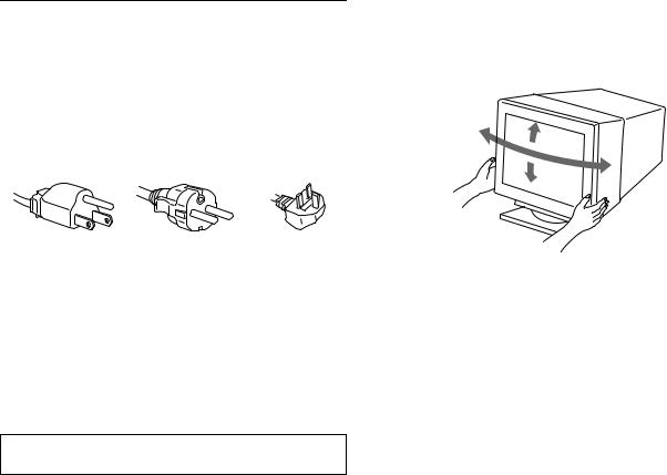
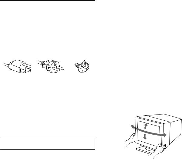
Use of the tilt-swivel
This monitor can be adjusted within the angles shown below. To turn the monitor vertically or horizontally, hold it at the bottom with both hands.
90°
15°
90°
5°
4
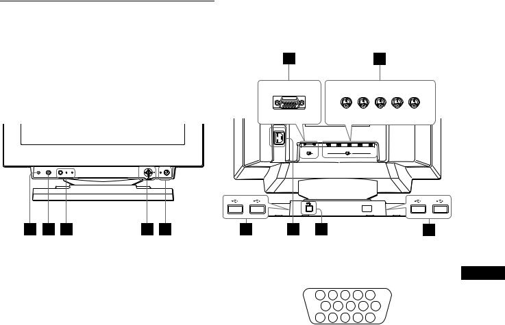
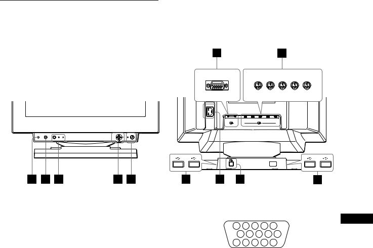
Identifying parts and controls
See the pages in parentheses for further details.
Front |
Rear |
forward side |
forward side |
rear side |
rear side |
AC IN |
|
R |
G B H D V D |
1 |
2 |
(HD15) |
(BNC) |
RESET |
ASC |
INPUT HD15 BNC |
MENU |
1RESET (reset) button (page 16)
This button resets the adjustments to the factory settings.
2ASC (auto sizing and centering) button (page 9)
This button automatically adjusts the size and centering of the picture.
3INPUT button and HD15 / BNC indicators (page 9)
This button selects the HD15 or BNC video input signal. Each time you press this button, the input signal and corresponding indicator alternate.
4Joystick (page 11)
The joystick is used to display the menu and make adjustments to the monitor, including brightness and contrast adjustments.
51 (power) switch and indicator (pages 7, 16, 20)
This button turns the monitor on and off. The power indicator lights up in green when the monitor is turned on, and either flashes in green and orange, or lights up in orange when the monitor is in power saving mode.
6AC IN connector (page 7)
This connector provides AC power to the monitor.
7USB (universal serial bus) upstream connector (page 8)
Use this connector to link the monitor to a USB compliant computer.
8USB (universal serial bus) downstream connectors (page 8)
Use these connectors to link USB peripheral devices to the monitor.
9 Video input 1 connector (HD15) (page 6)
This connector inputs RGB video signals (0.700 Vp-p,
positive) and sync signals. |
|
|
|
GB |
|||
|
5 |
|
4 |
3 |
2 |
1 |
|
|
10 |
9 |
8 |
7 |
6 |
|
|
|
15 |
14 |
13 12 |
11 |
|
||
|
|
|
|
|
|
|
|
Pin No. |
Signal |
|
|
|
|
|
|
|
|
|
|
|
|
|
|
1 |
Red |
|
|
|
|
|
|
|
|
|
|
|
|
|
|
2 |
Green |
|
|
|
|
|
|
|
(Composite Sync on Green) |
||||||
|
|
|
|
|
|
|
|
3 |
Blue |
|
|
|
|
|
|
|
|
|
|
|
|
||
4 |
ID (Ground) |
|
|
|
|
||
|
|
|
|
|
|
||
5 |
DDC Ground* |
|
|
|
|
||
|
|
|
|
|
|
||
6 |
Red Ground |
|
|
|
|
||
|
|
|
|
|
|
||
7 |
Green Ground |
|
|
|
|
||
|
|
|
|
|
|
||
8 |
Blue Ground |
|
|
|
|
||
|
|
|
|
|
|
|
|
9 |
DDC + 5V* |
|
|
|
|
|
|
|
|
|
|
|
|
|
|
10 |
Ground |
|
|
|
|
|
|
|
|
|
|
|
|
||
11 |
ID (Ground) |
|
|
|
|
||
|
|
|
|||||
12 |
Bi-Directional Data (SDA)* |
||||||
|
|
|
|
|
|
|
|
13 |
H. Sync |
|
|
|
|
|
|
|
|
|
|
|
|
|
|
14 |
V. Sync |
|
|
|
|
|
|
|
|
|
|
|
|||
15 |
Data Clock (SCL)* |
|
|
|
|||
|
|
|
|
|
|
|
|
* DDC (Display Data Channel) is a standard of VESA.
q; Video input 2 connector (BNC) (page 6)
This connector inputs RGB video signals (0.700 Vp-p, positive) and sync signals.
5
Setup
Before using your monitor, check that the following accessories are included in your carton:
•Power cord (1)
•HD15 video signal cable (1)
•USB cable (1)
•G3 adapter (for Macintosh blue and white system) (1)
•Setup Disk (1)
•Warranty card (1)
•Notes on cleaning the screen’s surface (1)
•This instruction manual (1)
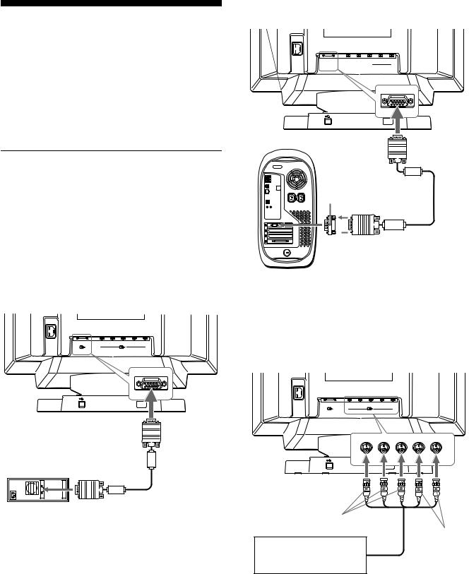
Step 1: Connect your monitor to your computer
Turn off the monitor and computer before connecting.
Notes
•Do not touch the pins of the video signal cable connector as this might bend the pins.
•When connecting the video signal cable, check the alignment of the HD15 connector. Do not force the connector in the wrong way or the pins might bend.
xConnecting to an IBM PC/AT or compatible computer
AC IN
R |
G |
B |
H D |
V D |
1 |
|
2 |
|
|
(HD15) |
|
(BNC) |
|
|
|
to HD15 |
to video output |
|
|
HD15 video signal |
IBM PC/AT or compatible |
cable (supplied) |
computer |
|
x Connecting to a Macintosh computer
Use the supplied G3 adapter (for blue and white system).
AC IN
R G B H D V D  1
1 
 2
2
(HD15)
to HD15
G3 adapter (for blue and white system) (supplied)*
 HD15 video signal to video cable (supplied) output
Power Macintosh G3
*Connect the supplied Macintosh adapter to the computer before connecting the cable. This adapter is compatible with the Power Macintosh G3 computer that has three rows of pins. If you are connecting to the other version of Power Macintosh G3 series computer with two rows of pins or other models, you will need a different adapter (sold separately).
x Connecting to the five BNC connectors
AC IN
R |
G |
B |
H D |
V D |
1 |
|
2 |
|
|
(HD15) |
|
(BNC) |
|
|
to VIDEO IN R/G/B
to SYNC IN
HD/VD
Refer to the preceding examples to connect to your
computer. video signal cable (SMF-400, not supplied)*
*Connect the cables from left to right in the following order: Red-Green- Blue-HD-VD.
Note
Plug & Play (DDC) does not apply to the five BNC connectors. If you want to use Plug & Play, connect your computer to the HD15 connector using the supplied video signal cable.
6
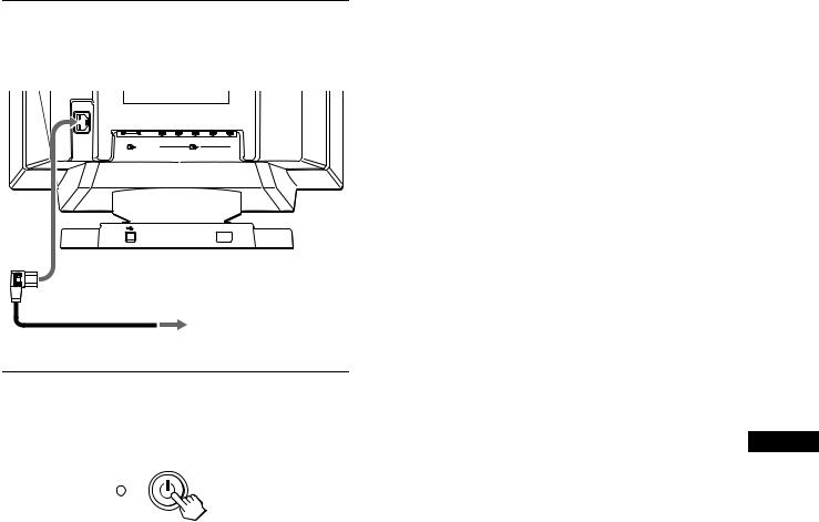
Step 2: Connect the power cord
With the monitor and computer switched off, first connect the power cord to the monitor, then connect it to a power outlet.
AC IN
R |
G |
B |
H D |
V D |
1 |
|
2 |
|
|
(HD15) |
|
(BNC) |
|
|
to AC IN
to a power outlet
power cord (supplied)
Step 3: Turn on the monitor and computer
First turn on the monitor, then turn on the computer.
The installation of your monitor is complete.
If necessary, use the monitor’s controls to adjust the picture.
If no picture appears on your screen
•Check that the monitor is correctly connected to the computer.
•If NO INPUT SIGNAL appears on the screen, try changing the input signal (page 9), and confirm that your computer’s graphic board is completely seated in the correct bus slot.
•If you are replacing an old monitor with this model and OUT OF SCAN RANGE appears on the screen, reconnect the old monitor. Then adjust the computer’s graphic board so that the horizontal frequency is between 30 – 121 kHz, and the vertical frequency is between 48 – 160 Hz.
For more information about the on-screen messages, see “Trouble symptoms and remedies” on page 18.
Setup on various OS (Operating System) |
|
This monitor complies with the “DDC” Plug & Play standard and |
|
automatically detects all the monitor’s information with the Windows |
|
Plug & Play function. No specific driver needs to be installed to the |
|
computer. |
|
If you connect the monitor to your PC, and then boot your PC for the first |
|
time, the setup Wizard may be displayed on the screen. Click on “Next” |
|
several times according to the instructions from the Wizard until the Plug |
|
& Play Monitor is automatically selected so that you can use this monitor. |
|
If your PC/graphics board has difficulty communicating with this |
|
monitor, load the supplied Setup Disk. Refer to the “Read Me” file on the |
|
Disk about the procedure to install. You can also download the |
|
information by accessing the web site of the graphics board’s |
GB |
manufacturer. |
|
For customers using Windows NT4.0 |
|
Monitor setup in Windows NT4.0 does not use the display driver. Refer |
|
to the Windows NT4.0 instruction manual for further details on adjusting |
|
the resolution, refresh rate, and number of colors. |
|
7
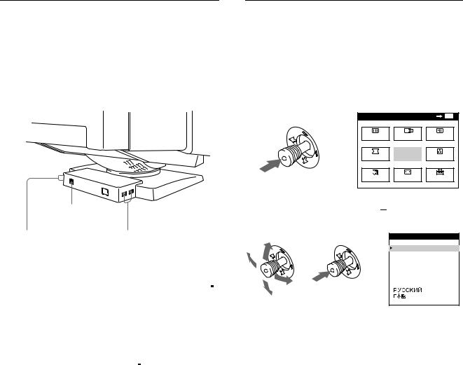
Connecting Universal Serial Bus (USB) compliant peripherals
Your monitor has one upstream and four downstream USB connectors. They provide a fast and easy way to connect USB compliant peripheral devices (such as keyboards, mice, printers and scanners) to your computer using a standardized USB cable. To use your monitor as a hub for your peripheral devices, connect the USBs as illustrated below.
to a USB compliant computer
to USB compliant |
to USB compliant |
peripheral devices |
peripheral devices |
1Turn on the monitor and computer.
2Connect your computer to the square upstream
 connector using the supplied USB cable.
For customers using Windows
If a message appears on your screen, follow the on-screen instructions and select Generic USB Hub as the default setting.
3Connect your USB compliant peripheral devices to the rectangular downstream 
 USB connectors.
Notes
•Not all computers and /or operating systems support USB configurations. Check your computer’s instruction manual to see if you can connect USB devices.
•In most cases, USB driver software needs to be installed on the host computer. Refer to the peripheral device’s instruction manual for further details.
•The monitor functions as a USB hub as long as the monitor is either “on” or in power saving mode.
•If you connect a keyboard or mouse to the USB connectors and then boot your computer for the first time, the peripheral devices may not function. First connect the keyboard and mouse directly to the computer and set up the USB compliant devices. Then connect them to this monitor.
•Do not lean on the monitor when plugging in the USB cables. The monitor may suddenly shift and cause injury.
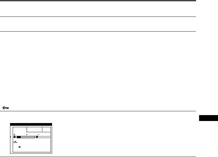
Selecting the on-screen menu language (LANG)
English, French, German, Spanish, Italian, Dutch, Swedish, Russian and Japanese versions of the on-screen menus are available. The default setting is English.
1Press the joystick.
See page 11 for more information on using the joystick.
MENU |
|
OK |
MENU |
SCREEN |
CENTER |
CONV |
|
b |
EXIT |
COLOR |
|
GEOM |
|||
LANG |
SIZE |
OPTION |
|
2Move the joystick to highlight 
 LANG and press the joystick again.
|
|
L ANGUAGE |
|
|
ENGL I SH |
|
|
FRANÇA I S |
b |
b |
DEUT SCH |
ESPAÑOL |
||
|
|
I T A L I ANO |
|
|
NEDER L ANDS |
|
|
SVENSKA |
3Move the joystick up or down to select a language and press the joystick again.
•ENGLISH
•FRANÇAIS: French
•DEUTSCH: German
•ESPAÑOL: Spanish
•ITALIANO: Italian
•NEDERLANDS: Dutch
•SVENSKA: Swedish
•


 : Russian
•
 : Japanese
To close the menu
Press the joystick once to return to the main menu, and twice to return to normal viewing. If no buttons are pressed, the menu closes automatically after about 30 seconds.
To reset to English
Press the RESET button while the LANGUAGE menu is displayed on the screen.
8

Selecting the input signal
You can connect two computers to this monitor using the HD15 and BNC connectors. To switch between the two computers, use the INPUT button.
Press the INPUT button.
Each time you press this button, the input signal and corresponding indicator alternate.
When the button is pressed, BNC is selected, when the button is unpressed, HD15 is selected.
HD15
INPUT |
BNC |
The selected connector appears on the screen for a few seconds. “HD15” or “BNC” appears on the screen.
Note
If no signal is input to the selected connector, NO INPUT SIGNAL appears on the screen. After a few seconds, the monitor enters the power saving mode. If this happens, switch to the other connector.
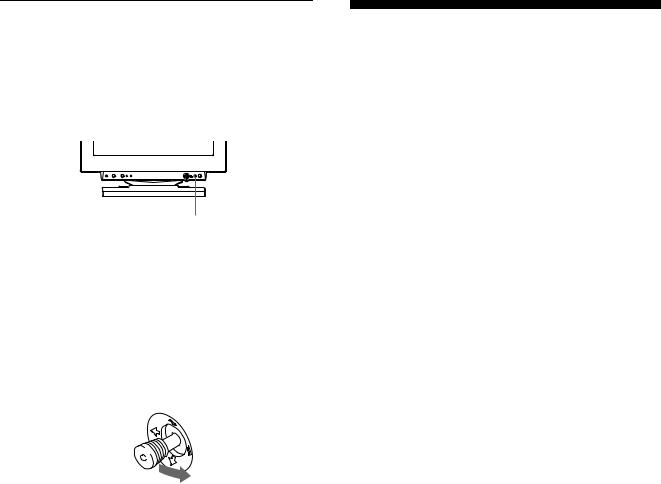
Automatically sizing and centering the picture (AUTO)
You can easily adjust the picture to fill the screen by pressing the ASC (auto sizing and centering) button, or by using the on-screen menu.
x Using ASC button
Press the ASC button.
The picture automatically fills the screen.
ASC
x Using the on-screen menu
1Press the joystick to display the main MENU on the screen.
MENU |
|
OK |
MENU |
SCREEN |
CENTER |
CONV |
|
b |
EXIT |
COLOR |
|
GEOM |
|||
LANG |
SIZE |
OPTION |
|
2Move the joystick to highlight 
 CENTER or
 SIZE and press the joystick again.
|
S I ZE / CENTER |
b |
b |
|
2 6 |
3 Move the joystick up or down to select  (AUTO).
|
S I ZE / CENTER |
GB |
b |
AUTO |
|
|
|
|
|
ON |
|
4Move the joystick to the right ,.
The picture automatically fills the screen.
Notes
•This function is intended for use with a computer running Windows or similar graphic user interface software that provides a full-screen picture. It may not work properly if the background color is dark or if the input picture does not fill the screen to the edges (such as an MSDOS prompt).
•Pictures with an aspect ratio of 5:4 (resolution: 1280 × 1024, 1800 × 1440) are displayed at their actual resolution and do not fill the screen to the edges.
•The displayed image moves for a few seconds while this function is performed. This is not a malfunction.
9
Customizing Your Monitor
You can make numerous adjustments to your monitor using the on-screen menu.
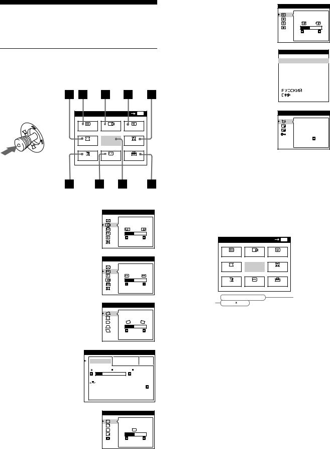
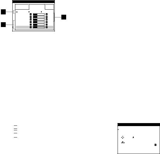
Navigating the menu
Press the joystick to display the main MENU on your screen. See page 11 for more information on using the joystick.
6CONV (page 12)
Select the CONV menu to adjust the picture’s horizontal and vertical convergence.
7LANG (page 8)
Select the LANG menu to choose the on-screen menu’s language.
CONVERGENCE |
TOP |
BOT |
2 6 |
L ANGUAGE
 ENGL I SH
FRANÇA I S
DEUT SCH
ESPAÑOL
I T A L I ANO
NEDER L ANDS
SVENSKA
|
MENU |
|
OK |
MENU |
|
SCREEN |
CENTER |
CONV |
|
b |
GEOM |
EXIT |
COLOR |
|
|
LANG |
SIZE |
OPTION |
|
Use the joystick to select one of the following menus.
1CENTER (page 12)
Select the CENTER menu to adjust the picture’s centering, size or zoom.
2SIZE (page 11)
Select the SIZE menu to adjust the picture’s size, centering or zoom.
S I ZE / CENTER |
2 6 |
S I ZE / CENTER |
2 6
3 GEOM (page 12) |
|
GEOMETRY |
|
|
Select the GEOM menu to adjust the |
|
|
||
picture’s rotation and shape. |
|
|
|
|
|
|
|
2 6 |
|
4 COLOR (page 13) |
COLOR |
|
|
|
Select the COLOR menu to |
EASY |
EXPERT |
s RGB |
|
adjust the picture’s color |
||||
5 0 0 0 K 6 5 0 0 K 9 3 0 0 K |
||||
temperature. You can use |
||||
|
|
5 0 0 0 K |
||
this to match the monitor’s |
I MAGE |
|
||
colors to a printed picture’s |
RES TORA T I ON |
ON |
||
colors. |
|
|
|
|
5 SCREEN (page 13) |
|
SCREEN |
|
|
Select the SCREEN menu to adjust |
L AND I NG |
|
the picture’s quality. You can adjust |
||
|
||
the landing and moire cancellation |
2 6 |
|
effect. |
||
|
8 OPTION (page 15) |
OPT I ON |
||
Select the OPTION menu to adjust |
DEGAUSS |
||
the monitor’s options. The options |
|||
|
|||
include: |
ON |
||
• |
degaussing the screen |
||
|
|||
• |
changing the on-screen menu |
|
|
|
position |
|
|
• |
locking the controls |
|
|
9EXIT
Select EXIT to close the menu.
x Displaying the current input signal
The horizontal and vertical frequencies of the current input signal are displayed in the main MENU. If the signal matches one of this monitor’s factory preset modes, the resolution is also displayed.
the resolution of the current input signal
MENU |
|
|
|
OK |
MENU |
SCREEN |
CENTER |
CONV |
|||
GEOM |
|
EXIT |
COLOR |
||
LANG |
|
|
SIZE |
OPTION |
|
68 . 7kHz / |
85Hz |
|
|
||
1024 |
768 |
|
|
|
|
the horizontal and vertical frequencies of the current input signal
10
x Using the joystick
1Display the main MENU and select the menu you want to adjust.
Press the joystick once to display the main MENU. Then move the joystick up, down, left, or right to highlight the desired menu. Press the joystick to select the menu item.


 b
b


 b
b
2Adjust the menu.
Move the joystick up, down, left, or right to make the adjustment.
3Close the menu.
Press the joystick once to return to the main menu, and twice to return to normal viewing. If no buttons are pressed, the menu closes automatically after about 30 seconds.
Adjusting the brightness and contrast
Brightness and contrast adjustments are made using a separate BRIGHTNESS/CONTRAST menu.
These settings are stored in memory for the signals from the currently selected input connector.
1Move the joystick in any direction.
The BRIGHTNESS/CONTRAST menu appears on the screen.
BR I GHTNESS / CONTRAS T
|
|
|
|
|
2 6 |
|
2 6 |
||
2Move the joystick up or down to adjust the brightness (  ), and left or right to adjust the contrast (6).
If you are using the sRGB mode
If you selected the sRGB mode in the COLOR menu, the following BRIGHTNESS/CONTRAST menu appears on the screen.
GB
BR I GHTNESS / CONTRAS T
5 6 |
|
7 6 |
s RGB : |
5 6 |
7 6 |
For more information about using the sRGB mode, see “Adjusting the color of the picture (COLOR)” on page 13.
The menu automatically disappears after about 3 seconds.
x Resetting the adjustments
Press the RESET button. See page 16 for more information on resetting the adjustments.
RESET
Adjusting the size of the picture (SIZE)
This setting is stored in memory for the current input signal.
1Press the joystick.
The main MENU appears on the screen.
2Move the joystick to highlight  SIZE and press the joystick again.
The SIZE/CENTER menu appears on the screen.
3First move the joystick up or down to select  for horizontal adjustment, or
  for vertical adjustment. Then move the joystick left or right to adjust the size.
11
Adjusting the centering of the picture (CENTER)
This setting is stored in memory for the current input signal.
1Press the joystick.
The main MENU appears on the screen.
2Move the joystick to highlight 
 CENTER and press the joystick again.
The SIZE/CENTER menu appears on the screen.
3First move the joystick up or down to select 
 for horizontal adjustment, or
  for vertical adjustment. Then move the joystick left or right to adjust the centering.
Enlarging or reducing the picture (ZOOM)
This setting is stored in memory for the current input signal.
1Press the joystick.
The main MENU appears on the screen.
2Move the joystick to highlight  SIZE or
 CENTER and press the joystick again.
The SIZE/CENTER menu appears on the screen.
3Move the joystick up or down to select 
 (zoom), and move the joystick left or right to enlarge or reduce the picture.
Note
Adjustment stops when either the horizontal or vertical size reaches its maximum or minimum value.
Adjusting the shape of the picture (GEOM)
The GEOM settings allow you to adjust the rotation and shape of the picture.
The  (rotation) setting is stored in memory for all input signals. All other settings are stored in memory for the current input signal.
1Press the joystick.
The main MENU appears on the screen.
2Move the joystick to highlight  GEOM and press the joystick again.
The GEOMETRY menu appears on the screen.
3First move the joystick up or down to select the desired adjustment item. Then move the joystick left or right to make the adjustment.
Select To
rotate the picture
expand or contract the picture sides
shift the picture sides to the left or right
adjust the picture width at the top of the screen
shift the picture to the left or right at the top of the screen
Adjusting the convergence (CONV)
The CONV settings allow you to adjust the quality of the picture by controlling the convergence. The convergence refers to the alignment of the red, green, and blue color signals.
If you see red or blue shadows around letters or lines, adjust the convergence.
These settings are stored in memory for all input signals.
1Press the joystick.
The main MENU appears on the screen.
2Move the joystick to highlight  CONV and press the joystick again.
The CONVERGENCE menu appears on the screen.
3First move the joystick up or down to select the desired adjustment item. Then move the joystick left or right to make the adjustment.
Select |
To |
|||
|
|
|
|
horizontally shift red or blue shadows |
|
|
|
|
|
|
|
|
|
|
|
|
|
|
vertically shift red or blue shadows |
|
|
|
|
|
|
|
|
TOP |
vertically shift red or blue shadows at |
|
|
|
the top of the screen |
|
V CONVER TOP |
||||
|
|
|
|
|
|
|
|
BOT |
vertically shift red or blue shadows at |
|
|
|
the bottom of the screen |
|
V CONVER |
||||
BOTTOM |
|
|||
|
|
|
|
|
12
Adjusting the quality of the picture (SCREEN)
The SCREEN settings allow you to adjust the quality of the picture by controlling the moire and landing.
•If the color is irregular at the corners of the screen, adjust the landing.
•If elliptical or wavy patterns appear on the screen, cancel the moire.
The CANCEL MOIRE and MOIRE ADJUST settings are stored in memory for the current input signal. All other settings are stored in memory for all input signals.
1Press the joystick.
The main MENU appears on the screen.
2Move the joystick to highlight  SCREEN and press the joystick again.
The SCREEN menu appears on the screen.
3First move the joystick up or down to select the desired adjustment item. Then move the joystick left or right to make the adjustment.
Select |
To |
|
reduce any color irregularities in the |
LANDING |
screen’s top left corner to a minimum. |
|
|
|
reduce any color irregularities in the |
LANDING |
screen’s top right corner to a |
|
minimum. |
|
|
|
reduce any color irregularities in the |
LANDING |
screen’s bottom left corner to a |
|
minimum. |
|
|
|
reduce any color irregularities in the |
LANDING |
screen’s bottom right corner to a |
|
minimum. |
|
|
|
turn the moire cancellation function |
CANCEL MOIRE* |
ON or OFF. |
|
(MOIRE ADJUST) appears in |
|
the menu when you select ON. |
|
|
|
adjust the degree of moire |
MOIRE ADJUST |
cancellation until the moire is at a |
|
minimum. |
|
|
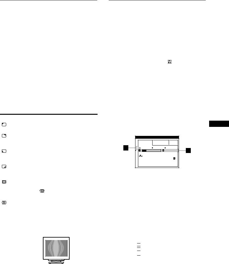
*Moire is a type of natural interference which produces soft, wavy lines on your screen. It may appear due to interference between the pattern of the picture on the screen and the phosphor pitch pattern of the monitor.
Example of moire
Note
The picture may become fuzzy when CANCEL MOIRE is set to ON.
Adjusting the color of the picture (COLOR)
The COLOR settings allow you to adjust the picture’s color temperature by changing the color level of the white color field. Colors appear reddish if the temperature is low, and bluish if the temperature is high. This adjustment is useful for matching the monitor’s color to a printed picture’s colors.
1 |
Press the joystick. |
|
|
The main MENU appears on the screen. |
|
2 |
Move the joystick to highlight |
COLOR and press |
|
the joystick again. |
|
|
The COLOR menu appears on the screen. |
|
3 |
Move the joystick left or right to select the |
|
|
adjustment mode. |
|
|
There are three types of adjustment modes, EASY, EXPERT |
|
|
and sRGB. |
|
4 |
First move the joystick up or down to select the |
|
|
desired adjustment item. Then move the joystick left |
|
|
or right to make the adjustment. |
|
|
Adjust the selected mode according to the following |
|
instructions.
GB
EASY mode
COLOR |
|
|
EASY |
EXPERT |
s RGB |
5 0 0 0 K 6 5 0 0 K 9 3 0 0 K |
||
|
|
5 0 0 0 K |
I MAGE |
|
|
RES TORA T I ON |
ON |
|
1Move the joystick up or down to select the color temperature row 1. Then move the joystick left or right to select a color temperature.
The preset color temperatures are 5000K, 6500K, and 9300K. Since the default setting is 9300K, the whites will change from a bluish hue to a reddish hue as the temperature is lowered to 6500K and 5000K.
2If necessary, fine tune the color temperature.
Move the joystick up or down to select the color temperature row 2. Then move the joystick left or right to fine tune the color temperature.
If you fine tune the color temperature, the new color settings
are stored in memory for each of the three color temperatures and item 1of the on-screen menu changes as follows.
•[5000K] t[ 

 1]
1]
•[6500K] t[ 

 2]
2]
•[9300K] t[ 

 3]
3]
(continued)
13
EXPERT mode
You can make additional adjustments to the color in greater detail by selecting the EXPERT mode.
COLOR |
|
|
|
EASY |
EXPERT |
s RGB |
|
5 0 0 0 K 6 5 0 0 K 9 3 0 0 K |
|||
R |
B I AS |
|
5 0 |
G |
B I AS |
|
5 0 |
B |
B I AS |
|
5 0 |
R |
GA I N |
|
5 0 |
G |
GA I N |
|
5 0 |
B |
GA I N |
|
5 0 |
1Move the joystick up or down to select the color temperature row 1. Then move the joystick left or right to select a color temperature.
2Move the joystick up or down to select the adjustment item 2. Then move joystick left or right to adjust the BIAS (black level).
This adjusts the dark areas of an image.
3Move the joystick up or down to select the adjustment item 3. Then move the joystick left or right to adjust the GAIN (white level).
This adjusts the light areas of an image.
You can adjust the R (red), G (green), B (blue) component of the input signal when making changes to items 2and 3.
If you fine tune the color temperature, the new color settings
are stored in memory for each of the three color temperatures and item 1of the on-screen menu change as follows.
•[5000K] t[ 

 1]
1]
•[6500K] t[ 

 2]
2]
•[9300K] t[ 

 3]
3]
Setting the color temperature for each of the video input connectors
You can set the fine tuning of the color temperature in EASY or EXPERT mode for each of the video input connectors (HD15 and BNC).
1Select the same adjustment mode and color temperature in the COLOR menu for both HD15 and BNC.
2Fine tune the color temperature in each menu for HD15 and BNC.
The settings are stored in memory for each of the HD15 and BNC connectors.
For information on how to select the connector, see page 9.
sRGB mode
The sRGB color setting is an industry standard color space protocol designed to correlate the displayed and printed colors of sRGB compliant computer products. To adjust the colors to the
sRGB profile, simply select the sRGB mode in the COLOR menu. However, in order to display the sRGB colors correctly (γ=2.2,
6500K), you must set your computer to the sRGB profile and adjust the brightness (  ) and contrast (6) to the numbers shown in the menu. For information on how to change the brightness
(  ) and contrast (6), see page 11.
Note
Your computer and other connected products (such as a printer), must be sRGB compliant.
COLOR
|
|
|
|
|
|
|
EASY |
|
EXPERT |
|
s RGB |
|
|
|
|
|
|
|
|
|
: 5 6 |
|
: 7 6 FOR |
|
s RGB |
|
|
I MAGE |
|
|
|
|
|
|
RES TORA T I ON |
ON |
|
||||
|
|
|
|
|
|
|
14

Restoring the color from the EASY or sRGB menus
The colors of most display monitors tend to gradually lose brilliance over several years of service. The IMAGE RESTORATION feature found in the EASY and sRGB menus allows you to restore the color to the original factory quality levels. The explanation below explains how to restore the monitor’s color from the EASY menu.
1Move the joystick left or right to select EASY or sRGB mode.
2First move the joystick up or down to select
 (IMAGE RESTORATION). Then move the joystick to the right.
The picture disappears while the color is being restored (about 2 seconds). After the color is restored, the picture reappears on the screen again.
Notes
•Before using this feature, the monitor must be in normal operation mode (green power indicator on) for at least 30 minutes. If the monitor goes into power saving mode, you must return the monitor to normal operation mode and wait for 30 minutes for the monitor to be ready. You may need to adjust your computer’s power saving settings to keep the monitor in normal operation mode for the full 30 minutes. If the monitor is not ready, the following message will appear.
COLOR |
|
|
EASY |
EXPERT |
s RGB |
5 0 0 0 K 6 5 0 0 K 9 3 0 0 K |
||
|
|
5 0 0 0 K |
I MAGE |
|
|
RES TORA T I ON |
|
|
|
AVA I L AB L E |
|
|
A F T ER WARM UP |
|
•The monitor may gradually lose its ability to perform this function due to the natural aging of the picture tube.
Additional settings (OPTION)
You can manually degauss (demagnetize) the monitor, change the menu position, and lock the controls.
1Press the joystick.
The main MENU appears on the screen.
2Move the joystick to highlight  OPTION and press the joystick again.
The OPTION menu appears on the screen.
3Move the joystick up or down to select the desired adjustment item.
Adjust the selected item according to the following instructions.
Degaussing the screen
The monitor is automatically demagnetized (degaussed) when the power is turned on.
To manually degauss the monitor, first move the
joystick up or down to select |
(DEGAUSS). Then |
|
move the joystick to the right. |
|
|
The screen is degaussed for about 2 seconds. If a second degauss |
||
cycle is needed, allow a minimum interval of 20 minutes for the |
||
best result. |
|
|
|
GB |
|
Changing the menu’s position
Change the menu’s position if it is blocking an image on the screen.
To change the menu’s on-screen position, first move the joystick up or down to select  (OSD H POSITION) for horizontal adjustment, or
  (OSD V POSITION) for vertical adjustment. Then move the joystick left or right to shift the on-screen menu.
Locking the controls
To protect adjustment data by locking the controls, first move the joystick up or down to select  (CONTROL LOCK). Then move the joystick to the right, to select ON.
Only the 1 (power) switch, EXIT, and  (CONTROL LOCK) of the
  OPTION menu will operate. If any other items are selected, the
  mark appears on the screen.
To cancel the control lock
Repeat the procedure above and set  (CONTROL LOCK) to OFF.
15

Resetting the adjustments
This monitor has the following three reset methods. Use the RESET button to reset the adjustments.
RESET
Resetting a single adjustment item
Use the joystick to select the adjustment item you want to reset, and press the RESET button.
Resetting all of the adjustment data for the current input signal
Press the RESET button when no menu is displayed on the screen. Note that the following items are not reset by this method:
•on-screen menu language (page 8)
•adjustment mode in the COLOR menu (EASY, EXPERT, sRGB) (page 13)
•on-screen menu position (page 15)
•control lock (page 15)
Resetting all of the adjustment data for all input signals
Press and hold the RESET button for more than two seconds.
Note
The RESET button does not function when  (CONTROL LOCK) is set to ON.
Technical Features
Preset and user modes
When the monitor receives an input signal, it automatically matches the signal to one of the factory preset modes stored in the monitor’s memory to provide a high quality picture at the center of the screen. (See Appendix for a list of the factory preset modes.) For input signals that do not match one of the factory preset modes, the digital Multiscan technology of this monitor ensures that a clear picture appears on the screen for any timing in the monitor’s frequency range (horizontal: 30 – 121 kHz, vertical: 48 – 160 Hz). If the picture is adjusted, the adjustment data is stored as a user mode and automatically recalled whenever the same input signal is received.
Note for Windows users
For Windows users, check your video board manual or the utility program which comes with your graphic board and select the highest available refresh rate to maximize monitor performance.
Power saving function
This monitor meets the power-saving guidelines set by VESA, ENERGY STAR, and NUTEK. If the monitor is connected to a computer or video graphics board that is DPMS (Display Power Management Signaling) compliant, the monitor will automatically reduce power consumption in three stages as shown below.
Power mode |
Power |
1 (power) |
|
consumption* |
indicator |
|
|
|
normal |
≤ 145 W |
green |
operation |
|
|
|
|
|
1 standby |
≤ 15 W |
green and orange |
|
|
alternate |
|
|
|
2 suspend |
≤ 15 W |
green and orange |
(sleep)** |
|
alternate |
|
|
|
3 active off*** |
≤ 1 W |
orange |
(deep sleep)** |
|
|
|
|
|
power off |
0 W |
off |
|
|
|
*Figures reflect power consumption when no USB compatible peripherals are connected to the monitor.
**“Sleep” and “deep sleep” are power saving modes defined by the Environmental Protection Agency.
***When your computer enters in a power saving mode, the input signal is cut and NO INPUT SIGNAL appears on the screen. After a few seconds, the monitor enters power saving mode.
16
Troubleshooting
Before contacting technical support, refer to this section.
If thin lines appear on your screen (damper wires)
The lines you are experiencing on your screen are normal for the Trinitron monitor and are not a malfunction. These are shadows from the damper wires used to stabilize the aperture grille and are most noticeable when the screen’s background is light (usually white). The aperture grille is the essential element that makes a Trinitron picture tube unique by allowing more light to reach the screen, resulting in a brighter, more detailed picture.
Damper wires
On-screen messages
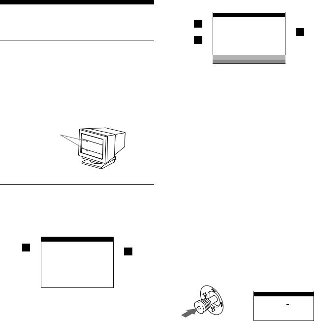
If there is something wrong with the input signal, one of the following messages appears on the screen.
If NO INPUT SIGNAL appears on the screen
I NFORMA T I ON
|
MON I TOR |
I S WORK I NG |
|
|||
|
|
HD 1 5 |
: |
|
|
|
|
|
|
||||
|
|
NO I NPUT |
S I GNA L |
|
|
|
|
|
|
|
|
|
|
|
WH I T E |
|
|
|
|
|
|
RED |
|
|
|
|
|
|
GREEN |
|
|
|
|
|
|
B L UE |
|
|
|
|
|
1The selected connector
This message shows the currently selected connector (HD15 or BNC).
2The input signal condition NO INPUT SINGAL
This indicates that no signal is input, or that no signal is input from the selected connector.
If OUT OF SCAN RANGE appears on the screen
I NFORMA T I ON
|
MON I TOR |
I S WORK I NG |
|
|||
|
|
BNC |
: 1 3 0 . 0 k H z / 7 5 H z |
|
||
|
|
|||||
|
|
|
|
|
||
|
OUT OF SCAN RANGE |
|
|
|||
|
|
|
|
|
|
|
|
CHANGE |
S I GNA L T I M I NG |
|
|||
|
|
|
|
|
|
|
|
WH I T E |
|
|
|
|
|
|
RED |
|
|
|
|
|
GREEN
B L UE
1The selected connector and the frequencies of the current input signal
This message shows the currently selected connector (HD15 or BNC). If the monitor recognizes the frequencies of the current input signal, the horizontal and vertical frequencies are also displayed.
2The input signal condition OUT OF SCAN RANGE
This indicates that the input signal is not supported by the monitor’s specifications.
3The remedies
CHANGE SIGNAL TIMING appears on the screen. If you are replacing an old monitor with this monitor, reconnect the old monitor. Then adjust the computer’s graphic board so that
the horizontal frequency is between 30 - 121 kHz, and the |
GB |
vertical frequency is between 48 - 160 Hz. |
|
For more information, see “Trouble symptoms and remedies” on |
|
page 18. |
|
Displaying this monitor’s name, serial number, and date of manufacture.
While the monitor is receiving a video signal, press and hold the joystick for more than three seconds to display this monitor’s information box.
Example
INFORMATION
b MODEL : GDM F500R SER NO : 1234567 MANUFACTURED : 1999-52
If the problem persists, call your authorized Sony dealer and give the following information.
•Model name: GDM-F500R
•Serial number
•Name and specifications of your computer and graphics board.
17

Trouble symptoms and remedies
If the problem is caused by the connected computer or other equipment, please refer to the connected equipment’s instruction manual. Use the self-diagnosis function (page 20) if the following recommendations do not resolve the problem.
Symptom |
Check these items |
|
No picture |
|
|
|
If the 1 (power) indicator is not lit |
• Check that the power cord is properly connected. |
|
|
• Check that the 1 (power) switch is in the “on” position. |
|
|
|
|
If the NO INPUT SIGNAL message |
• Check that the video signal cable is properly connected and all plugs are firmly seated in |
|
appears on the screen, or if the |
their sockets. If you are using the five BNC connectors, connect them in the correct order |
|
1 (power) indicator is either orange |
(from left to right: Red-Green-Blue-HD-VD) (page 6). |
|
or alternating between green and |
• Check that the INPUT switch setting is correct (page 9). |
|
orange |
• Check that the HD15 video input connector’s pins are not bent or pushed in. |
|
|
xProblems caused by the connected computer or other equipment |
|
|
• The computer is in power saving mode. Try pressing any key on the computer keyboard. |
|
|
• Check that the computer’s power is “on.” |
|
|
• Check that the graphic board is completely seated in the proper bus slot. |
|
|
|
|
If the OUT OF SCAN RANGE |
xProblems caused by the connected computer or other equipment |
|
message appears on the screen |
• Check that the video frequency range is within that specified for the monitor. If you |
|
|
replaced an old monitor with this monitor, reconnect the old monitor and adjust the |
|
|
frequency range to the following. |
|
|
Horizontal: 30 – 121 kHz |
|
|
Vertical: 48 – 160 Hz |
If no message is displayed and the 1 (power) indicator is green or flashing orange
• Use the Self-diagnosis function (page 20).
|
If using Windows 95/98 |
• |
If you replaced an old monitor with this monitor, reconnect the old monitor and do the |
|
|
|
following. Install the supplied Setup Disk (page 7) and select this monitor |
|
|
|
(“GDM-F500R”) from among the Sony monitors in the Windows 95/98 monitor selection |
|
|
|
screen. If you choose to select “Plug and Play,” connect the monitor to the computer with |
|
|
|
the HD15 video signal cable. You cannot use the five BNC connectors. |
|
|
|
|
|
If using a Macintosh system |
• |
When connecting to a Power Macintosh G3 series computer that has three rows of pins, |
|
|
|
check that the supplied G3 adapter and the video signal cable are properly connected |
|
|
|
(page 6). |
|
|
• For Power Macintosh G3 or other models which have two rows of pins, you will need a |
|
|
|
|
different adapter which is sold separately. |
|
|
|
|
Picture flickers, bounces, |
• |
Isolate and eliminate any potential sources of electric or magnetic fields such as other |
|
oscillates, or is scrambled |
|
monitors, laser printers, electric fans, fluorescent lighting, or televisions. |
|
|
|
• Move the monitor away from power lines or place a magnetic shield near the monitor. |
|
|
|
• Try plugging the monitor into a different AC outlet, preferably on a different circuit. |
|
|
|
• |
Try turning the monitor 90 ° to the left or right. |
xProblems caused by the connected computer or other equipment
•Check your graphics board manual for the proper monitor setting.
•Confirm that the graphics mode (VESA, Macintosh 21" Color, etc.) and the frequency of the input signal are supported by this monitor (Appendix). Even if the frequency is within the proper range, some video boards may have a sync pulse that is too narrow for the monitor to sync correctly.
•Adjust the computer’s refresh rate (vertical frequency) to obtain the best possible picture.
Picture is fuzzy |
• |
Adjust the brightness and contrast (page 11). |
|
• Degauss the monitor* (page 15). |
|
|
• |
If CANCEL MOIRE is ON, the picture may become fuzzy. Decrease the moire |
|
|
cancellation effect or set CANCEL MOIRE to OFF (page 13). |
|
|
|
18
Symptom |
Check these items |
|
Picture is ghosting |
• |
Eliminate the use of video cable extensions and/or video switch boxes. |
|
• |
Check that all plugs are firmly seated in their sockets. |
Picture is not centered or sized properly
•Perform the AUTO function (page 9).
•Adjust the size (page 11) or centering (page 12). Note that some video modes do not fill the screen to the edges.
Edges of the image are curved |
• Adjust the geometry (page 12). |
|
Wavy or elliptical pattern (moire) |
• Set CANCEL MOIRE to ON and adjust the degree of moire cancellation until the moire is |
|
is visible |
at a minimum (page 13). |
|
|
|
xProblems caused by the connected computer or other equipment |
|
|
• Change your desktop pattern. |
|
|
|
Color is not uniform |
• Degauss the monitor* (page 15). If you place equipment that generates a magnetic field, |
|
|
|
such as a speaker, near the monitor, or if you change the direction the monitor faces, color |
|
|
may lose uniformity. |
|
|
• Adjust the landing (page 13). |
|
|
|
White does not look white |
• Adjust the color temperature (page 13). |
|
|
|
• Check that the five BNC connectors are connected in the correct order (from left to right: |
|
|
Red-Green-Blue-HD-VD) (page 6). |
|
|
|
Letters and lines show red or blue |
• Adjust the convergence (page 12). |
|
shadows at the edges |
|
|
|
|
|
Monitor buttons do not operate |
• If the control lock is set to ON, set it to OFF (page 15). |
|
( |
appears on the screen) |
|
IMAGE RESTORATION function does not operate
COLOR |
|
|
EASY |
EXPERT |
s RGB |
5 0 0 0 K 6 5 0 0 K 9 3 0 0 K |
||
|
|
5 0 0 0 K |
I MAGE |
|
|
RES TORA T I ON |
|
|
|
AVA I L AB L E |
|
|
A F T ER WARM UP |
|
• Before using this function, the monitor must be in normal operation mode (green power
indicator on) for at least 30 minutes. For more information on using the IMAGE GB RESTORATION function, see page 15.
•Adjust the computer’s power saving settings to keep the monitor in normal operation mode for more than 30 minutes.
•The monitor may gradually lose its ability to perform this function due to the natural aging of the picture tube.
USB peripherals do not function |
• |
Check that the appropriate USB connectors are securely connected (page 8). |
|
• |
Check that the 1 (power) switch is in the “on” position. |
|
xProblems caused by the connected computer or other equipment |
|
|
• Check that the power of any self-powered USB compliant peripheral devices is “on.” |
|
|
• Install the latest version of the device driver on your computer. Contact your device’s |
|
|
|
manufacturer for information about the appropriate device driver. |
|
• If your USB compliant keyboard or mouse does not function, connect them directly to |
|
|
|
your computer, reboot your computer, and make any necessary adjustments to the USB |
|
|
settings. Then reconnect the keyboard or mouse to the monitor. |
|
• For customers using Windows 95 |
|
|
|
1. Right-click on My Computer and select Properties. |
|
|
2. Click on the Device Manager tab. Scroll down and select Universal Serial Bus |
|
|
Controller. |
|
|
,If Universal Serial Bus Controller does not appear, you need to load a USB |
|
|
supplement disk. Contact your computer’s manufacturer for more information about |
|
|
obtaining a USB supplement disk. |
|
|
3. Select Generic USB Device from the USB controller list and click on Properties. |
|
|
4. If there is a check in the box next to “Disable in this hardware profile,” remove the |
|
|
check. |
|
|
5. Click on Refresh. |
|
|
|
A hum is heard right after the |
• |
This is the sound of the auto-degauss cycle. When the power is turned on, the monitor is |
power is turned on |
|
automatically degaussed for three seconds. |
|
|
|
*If a second degauss cycle is needed, allow a minimum interval of 20 minutes for the best result. A humming noise may be heard, but this is not a malfunction.
19
Self-diagnosis function
This monitor is equipped with a self-diagnosis function. If there is a problem with your monitor or computer(s), the screen will go blank and the 1 (power) indicator will either light up green or flash orange. If the 1 (power) indicator is lit in orange, the computer is in power saving mode. Try pressing any key on the keyboard.
1 (power) indicator
If the 1 (power) indicator is green
1Remove any plugs from the video input 1 and 2 connectors, or turn off the connected computer(s).
2Press the 1 (power) button twice to turn the monitor off and then on.
3Move the joystick to the right , for 2 seconds before the monitor enters power saving mode.
If all four color bars appear (white, red, green, blue), the monitor is working properly. Reconnect the video input cables and check the condition of your computer(s).
If the color bars do not appear, there is a potential monitor failure. Inform your authorized Sony dealer of the monitor’s condition.
If the 1 (power) indicator is flashing orange
Press the 1 (power) button twice to turn the monitor off and then on.
If the 1 (power) indicator lights up green, the monitor is working properly.
If the 1 (power) indicator is still flashing, there is a potential monitor failure. Count the number of seconds between orange flashes of the 1 (power) indicator and inform your authorized Sony dealer of the monitor’s condition. Be sure to note the model name and serial number of your monitor. Also note the make and model of your computer and video board.
Specifications
CRT |
0.22 mm aperture grille pitch |
|
21 inches measured diagonally |
|
90-degree deflection |
|
FD Trinitron |
Viewable image size |
Approx. 403.8 × 302.2 mm (w/h) |
|
(16 × 12 inches) |
|
19.8" viewing image |
Resolution |
|
Maximum |
Horizontal: 2048 dots |
|
Vertical: 1536 lines |
Recommended |
Horizontal: 1600 dots |
|
Vertical: 1200 lines |
Standard image area |
Approx. 388 × 291 mm (w/h) |
|
(15 3/8 × 11 1/2 inches) |
|
or |
|
Approx. 364 × 291 mm (w/h) |
|
(14 3/8 × 11 1/2 inches) |
Deflection frequency* |
Horizontal: 30 to 121 kHz |
|
Vertical: 48 to 160 Hz |
AC input voltage/current |
100 to 240 V, 50 – 60 Hz, 2.0 – 1.0 A |
Power consumption |
Approx. 145 W (with no USB devices |
|
connected) |
Operating temperature |
10°C to 40°C |
Dimensions |
Approx. 502 × 511 × 480.3 mm (w/h/d) |
|
(19 7/8 × 20 1/8 × 19 1/4 inches) |
Mass |
Approx. 33 kg (72 lb 12 oz) |
Plug and Play |
DDC1/DDC2B/DDC2Bi, GTF** |
Supplied accessories |
See page 6 |
*Recommended horizontal and vertical timing condition
•Horizontal sync width duty should be more than 4.8% of total horizontal time or 0.8 µs, whichever is larger.
•Horizontal blanking width should be more than 2.3 µsec.
•Vertical blanking width should be more than 450 µsec.
**If the input signal is Generalized Timing Formula (GTF) compliant, the GTF feature of the monitor will automatically provide an optimal image for the screen.
Design and specifications are subject to change without notice.
20
Table des Matières
Précautions. . . . . . . . . . . . . . . . . . . . . . . . . . . . . . . . . . . . . . . . . . . . 4
Identification des composants et des commandes . . . . . . . . . . . . . . 5
Installation . . . . . . . . . . . . . . . . . . . . . . . . . . . . . . . . . . . . .6
1re étape:Raccordez le moniteur à l’ordinateur . . . . . . . . . . . . . . . 6 2e étape:Branchez le cordon d’alimentation . . . . . . . . . . . . . . . . . . 7 3e étape:Mettez le moniteur et l’ordinateur sous tension . . . . . . . . 7 Raccordement de périphériques compatibles USB
(Universal Serial Bus) . . . . . . . . . . . . . . . . . . . . . . . . . . . . . . . . . . . . 8 Sélection de la langue d’affichage des menus (LANG) . . . . . . . . . . 8 Sélection du signal d’entrée . . . . . . . . . . . . . . . . . . . . . . . . . . . . . . . 9 Taille et centrage automatiques de l’image (AUTO). . . . . . . . . . . . . 9
•Trinitron â est une marque commerciale déposée de Sony Corporation.
•Macintosh est une marque commerciale sous licence d’Apple Computer, Inc., déposée aux Etats-Unis et dans d’autres pays.
•Windowsâ et MS-DOS sont des marques déposées de Microsoft Corporation aux Etats-Unis et dans d’autres pays.
•IBM PC/AT et VGA sont des marques commerciales déposées d’IBM Corporation aux Etats-Unis.
•VESA et DDC ä sont des marques commerciales de Video Electronics Standard Association.
•ENERGY STAR est une marque déposée aux Etats-Unis.
•Tous les autres noms de produits mentionnés dans le présent mode d’emploi peuvent être des marques commerciales ou des marques commerciales déposées de leurs sociétés respectives.
•Les symboles “ ä” et “ â” ne sont pas mentionnés systématiquement dans le présent mode d’emploi.
Personnalisation de votre moniteur. . . . . . . . . . . . . . . .10
Pilotage par menus. . . . . . . . . . . . . . . . . . . . . . . . . . . . . . . . . . . . . 10 Réglage de la luminosité et du contraste . . . . . . . . . . . . . . . . . . . . 11 Réglage de la taille de l’image (TAILLE) . . . . . . . . . . . . . . . . . . . . 11 Réglage du centrage de l’image (CENTRE). . . . . . . . . . . . . . . . . . 12
Agrandir ou réduire l’image (ZOOM) . . . . . . . . . . . . . . . . . . . . . . . 12 FR Réglage de la forme de l’image (GEOM) . . . . . . . . . . . . . . . . . . . . 12
Réglage de la convergence (CONV) . . . . . . . . . . . . . . . . . . . . . . . 12 Réglage de la qualité de l’image (ECRAN). . . . . . . . . . . . . . . . . . . 13 Réglage des couleurs de l’image (COULEUR). . . . . . . . . . . . . . . . 13 Réglages supplémentaires (OPTION) . . . . . . . . . . . . . . . . . . . . . . 15 Réinitialisation des réglages . . . . . . . . . . . . . . . . . . . . . . . . . . . . . . 16
Caractéristiques techniques. . . . . . . . . . . . . . . . . . . . . .16
Modes présélectionné et utilisateur . . . . . . . . . . . . . . . . . . . . . . . . 16 Fonction d’économie d’énergie. . . . . . . . . . . . . . . . . . . . . . . . . . . . 16
Dépannage . . . . . . . . . . . . . . . . . . . . . . . . . . . . . . . . . . . .17
Si de fines lignes apparaissent à l’écran (fils d’amortissement) . . . 17 Messages affichés à l’écran . . . . . . . . . . . . . . . . . . . . . . . . . . . . . . 17 Symptômes et remèdes . . . . . . . . . . . . . . . . . . . . . . . . . . . . . . . . . 18 Fonction d’autodiagnostic . . . . . . . . . . . . . . . . . . . . . . . . . . . . . . . . 20
Spécifications. . . . . . . . . . . . . . . . . . . . . . . . . . . . . . . . . .20
Appendix. . . . . . . . . . . . . . . . . . . . . . . . . . . . . . . . . . . . . . . i
Preset mode timing table . . . . . . . . . . . . . . . . . . . . . . . . . . . . . . . . . .i TCO’99 Eco-document . . . . . . . . . . . . . . . . . . . . . . . . . . . . . . . . . . . .i
3
Précautions
Avertissement sur le raccordement à la source d’alimentation
•Utilisez le cordon d’alimentation fourni. Si vous utilisez un cordon d’alimentation différent, assurez-vous qu’il est compatible avec votre tension d’alimentation secteur locale.
Pour les clients au Royaume-Uni
Si vous utilisez ce moniteur au Royaume-Uni, utilisez le cordon d’alimentation fourni au Royaume-Uni.
Exemple de types de fiches
pour 100 à 120 V CA pour 200 à 240 V CA pour 240 V CA uniquement
•Avant de débrancher le cordon d’alimentation, attendez au moins 30 secondes après avoir actionné le commutateur d’alimentation de manière à permettre la décharge de l’électricité statique à la surface de l’écran.
•Après que le courant a été branché, l’écran est démagnétisé pendant environ 3 secondes. Cela génère un puissant champ magnétique autour de l’encadrement métallique qui peut affecter les données mémorisées sur une bande magnétique ou des disquettes situées à proximité. Placez ces systèmes d’enregistrement magnétique, bandes et disquettes à l’écart du moniteur.
L’appareil doit être installé à proximité d’une prise murale aisément accessible.
Installation
N’installez pas le moniteur dans les endroits suivants:
•sur des surfaces molles (moquette, nappe, etc.) ou à proximité de tissus (rideaux, tentures, etc.) qui risquent d’obstruer les orifices de ventilation
•à proximité de sources de chaleur comme des radiateurs ou des conduits d’air, ni dans un endroit directement exposé au rayonnement solaire
•sujet à de fortes variations de température
•soumis à des vibrations ou à des chocs mécaniques
•sur une surface instable
•à proximité d’appareils générant un champ magnétique comme un transformateur ou des lignes à haute tension
•à proximité de ou sur une surface métallique chargée électriquement
Entretien
•Nettoyez l’écran à l’aide d’un chiffon doux. Si vous utilisez un produit nettoyant pour vitres, n’utilisez aucun type de produit contenant une solution antistatique ou des additifs similaires parce que vous risquez de rayer le revêtement de l’écran.
•Ne frottez pas, ne touchez pas et ne tapotez pas la surface de l’écran avec des objets abrasifs ou aux arêtes vives comme un stylo à bille ou un tournevis. Ce type de contact risque en effet de rayer le tube image.
•Nettoyez le châssis, le panneau et les commandes à l’aide d’un chiffon doux légèrement imprégné d’une solution détergente neutre. N’utilisez jamais de tampons abrasifs, de poudre à récurer ou de solvants tels que de l’alcool ou du benzène.
Transport
Pour transporter ce moniteur en vue de réparations ou de son expédition, utilisez le carton d’emballage et les matériaux de conditionnement d’origine.
Utilisation du support pivotant
Ce moniteur peut être réglé suivant les angles précisés ci-dessous. Pour faire pivoter le moniteur verticalement et horizontalement, maintenez-le des deux mains par la base comme illustré cidessous.
90°
15°
90°
5°
4
Identification des composants et des commandes
Pour plus de détails, reportez-vous aux pages indiquées entre parenthèses.
Avant |
Arrière |
avant |
avant |
arrière |
arrière |
AC IN
R |
G |
B |
H D |
V D |
1 |
|
2 |
|
|
(HD15) |
|
(BNC) |
|
|
RESET |
ASC |
INPUT HD15 BNC |
MENU |
1Touche RESET (réinitialisation) (page 16)
Cette touche réinitialise les réglages aux valeurs par défaut.
2Touche ASC (taille & centrage automatiques) (page 9)
Cette touche ajuste automatiquement la taille et le centrage des images.
3Touche INPUT et indicateurs HD15 / BNC (page 9)
Cette touche sélectionne le signal d’entrée vidéo HD15 ou BNC.
Chaque fois que vous appuyez sur cette touche, le signal d’entrée et l’indicateur correspondant alternent.
4Manette de commande (page 11)
La manette de commande sert à afficher le menu et à ajuster les paramètres de réglage du moniteur, y compris la luminosité et le contraste.
5Commutateur et indicateur 1 (alimentation)
(pages 7, 16, 20)
Cette touche met le moniteur sous et hors tension. L’indicateur d’alimentation s’allume en vert lorsque le moniteur est sous tension et clignote en vert et en orange ou s’allume en orange lorsque le moniteur se trouve en mode d’économie d’énergie.
6Connecteur AC IN (page 7)
Ce connecteur assure l’alimentation du moniteur.
7Connecteur d’amont USB (bus sériel universel) (page 8)
Utilisez ce connecteur pour relier le moniteur à un ordinateur compatible USB.
8Connecteurs d’aval USB (bus sériel universel) (page 8)
Utilisez ces connecteurs pour relier des appareils périphériques USB au moniteur.
9Connecteur d’entrée vidéo 1 (HD15) (page 6)
Ce connecteur assure l’entrée des signaux vidéo RVB (0,700 Vp-p, positifs) et des signaux de synchronisation.
FR
|
5 |
4 |
|
3 |
2 |
1 |
|
10 |
9 |
8 |
7 |
6 |
|
|
15 |
14 |
13 12 |
11 |
||
|
|
|
|
|
|
|
Broche n° |
Signal |
|
|
|
|
|
|
|
|
|
|
|
|
1 |
Rouge |
|
|
|
|
|
|
|
|
|
|
|
|
2 |
Vert |
|
|
|
|
|
|
(Synchro composite sur le vert) |
|||||
|
|
|
|
|
|
|
3 |
Bleu |
|
|
|
|
|
|
|
|
|
|
|
|
4 |
ID (Masse) |
|
|
|
|
|
|
|
|
|
|
|
|
5 |
Masse DDC* |
|
|
|
|
|
|
|
|
|
|
|
|
6 |
Masse rouge |
|
|
|
|
|
|
|
|
|
|
|
|
7 |
Masse vert |
|
|
|
|
|
|
|
|
|
|
|
|
8 |
Masse bleu |
|
|
|
|
|
|
|
|
|
|
|
|
9 |
DDC +5 V* |
|
|
|
|
|
|
|
|
|
|
|
|
10 |
Masse |
|
|
|
|
|
|
|
|
|
|
|
|
11 |
ID (Masse) |
|
|
|
|
|
|
|
|||||
12 |
Données bidirectionnelles (SDA)* |
|||||
|
|
|
|
|
|
|
13 |
Synchro H |
|
|
|
|
|
|
|
|
|
|
|
|
14 |
Synchro V |
|
|
|
|
|
|
|
|||||
15 |
Données d’horloge (SCL)* |
|||||
|
|
|
|
|
|
|
* DDC (Display Data Channel) est une norme de VESA.
q; Connecteur d’entrée vidéo 2 (BNC) (page 6)
Ce connecteur assure l’entrée des signaux vidéo RVB (0,700 Vp-p, positifs) et des signaux de synchronisation.
5

Installation
Avant de mettre ce moniteur en service, vérifiez si tous les accessoires suivants se trouvent bien dans le carton:
•Cordon d’alimentation (1)
•Câble de signal vidéo HD15 (1)
•Câble USB (1)
•Adaptateur G3 (pour système Macintosh bleu et blanc) (1)
•Disquette d’installation (1)
•Carte de garantie (1)
•Remarques sur l’entretien de la surface de l’écran (1)
•Ce mode d’emploi (1)
1re étape: Raccordez le moniteur à l’ordinateur
Mettez le moniteur et l’ordinateur hors tension avant de procéder au raccordement.
Remarques
•Ne touchez pas les broches du connecteur du câble de signal vidéo, car vous risqueriez de les plier.
•Lorsque vous branchez le câble de signal vidéo, vérifiez l’alignement du connecteur HD15. Ne forcez pas le connecteur dans le mauvais sens, car vous risquez sinon de plier les broches.
xRaccordement à un PC/AT IBM ou à un ordinateur compatible
AC IN
R |
G |
B |
H D |
V D |
1 |
|
2 |
|
|
(HD15) |
|
(BNC) |
|
|
 vers HD15
vers la sortie vidéo
Câble de signal vidéo
HD15 (fourni)
PC/AT IBM ou ordinateur compatible
xRaccordement à un ordinateur Macintosh ou compatible
Utilisez l’adaptateur G3 fourni (pour système bleu et blanc)
AC IN
R G B H D V D  1
1 
 2
2
(HD15)
vers HD15
Adaptateur G3 (pour système bleu et blanc) (fourni)*
Câble de signal vidéo vers la sortie vidéo HD15 (fourni)
Power Macintosh G3
*Raccordez l’adaptateur Macintosh fourni à l’ordinateur avant de brancher le câble. Cet adaptateur est compatible avec les ordinateurs Power Macintosh G3 doté de trois rangées de broches. Si vous établissez la connexion avec une autre version d’ordinateur Power Macintosh G3 dotée de deux rangées de broches ou d’un autre modèle, vous aurez besoin d’un adaptateur différent (vendu séparément).
x Raccordement aux cinq connecteurs BNC
AC IN
R |
G |
B |
H D |
V D |
1 |
|
2 |
|
|
(HD15) |
|
(BNC) |
|
|
vers VIDEO IN R/G/B |
|
|
vers SYNC IN |
Voyez les exemples |
HD/VD |
|
|
précédents pour le |
|
raccordement à votre |
Câble de signal vidéo |
ordinateur. |
(SMF-400, non fourni)* |
*Raccordez les câbles de gauche à droite dans l’ordre suivant : Rouge- Vert-Bleu-HD-VD.
6
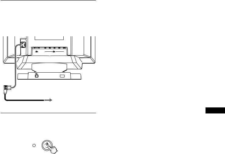
Remarque
La norme Plug & Play (DDC) ne s’applique pas aux cinq connecteurs BNC. Si vous utilisez la norme Plug & Play, raccordez le connecteur HD15 à l’ordinateur à l’aide du câble de signal vidéo fourni.
2e étape:Branchez le cordon d’alimentation
Le moniteur et l’ordinateur étant hors tension, branchez d’abord le cordon d’alimentation sur le moniteur et ensuite sur une prise murale.
AC IN
R |
G |
B |
H D |
V D |
1 |
|
2 |
|
|
(HD15) |
|
(BNC) |
|
|
vers AC IN
vers une prise murale
cordon d’alimentation (fourni)
3e étape:Mettez le moniteur et l’ordinateur sous tension
Mettez d’abord le moniteur sous tension et puis l’ordinateur.
L’installation de votre moniteur est à présent terminée.
Si nécessaire, utilisez les commandes du moniteur pour régler l’image.
Si aucune image n’apparaît à l’écran
•Vérifiez si le moniteur est correctement raccordé à l’ordinateur.
•Si l’indication PAS ENTREE VIDEO apparaît à l’écran, changez le signal d’entrée (page 9), et vérifiez si la carte graphique de votre ordinateur est complètement introduite dans la fente de bus appropriée.
•Si vous remplacez un ancien moniteur par ce modèle et si l’indication HORS PLAGE DE BALAYAGE apparaît à l’écran, rebranchez l’ancien moniteur. Ajustez ensuite la carte graphique de l’ordinateur de façon à ce que la fréquence horizontale soit comprise entre 30 et 121 kHz et la fréquence verticale entre 48 et 160 Hz.
Pour plus d’informations sur les messages affichés à l’écran, reportez-vous à la section “Symptômes et remèdes” à la page 18.
Installation sous différents systèmes d’exploitation
Ce moniteur est compatible avec la norme Plug & Play “DDC” et détecte automatiquement toutes les informations relatives au moniteur grâce à la fonction Plug & Play Windows. Aucun pilote spécifique ne doit être installé sur l’ordinateur.
Si vous raccordez le moniteur à votre PC et si vous démarrez votre PC pour la première fois, il se peut que l’assistant d’installation s’affiche à l’écran. Cliquez plusieurs fois de suite sur “Next” suivant les instructions de l’assistant jusqu’à ce que le moniteur Plug & Play soit automatiquement sélectionné de façon à ce que vous puissiez utiliser ce moniteur.
Si votre PC/carte graphique communique difficilement avec ce moniteur, chargez la disquette d’installation fournie. Pour la procédure
d’installation, consultez le fichier “Read Me” de la disquette. Vous FR pouvez également télécharger les informations en accédant au site web du fabricant de votre carte graphique.
Pour les clients utilisant Windows NT4.0
L’installation du moniteur sous Windows NT4.0 ne fait pas appel au pilote d’affichage. Reportez-vous au mode d’emploi de Windows NT4.0 pour des informations plus détaillées sur la résolution, le taux de régénération et le nombre de couleurs.
7

Raccordement de périphériques compatibles USB (Universal Serial Bus)
Votre moniteur est doté d’un connecteur USB d’amont et de quatre connecteurs USB d’aval. Ces connecteurs offrent un moyen simple et rapide de raccorder des périphériques compatibles USB (comme des claviers, une souris, des imprimantes et des scanners) à votre ordinateur au moyen d’un câble USB standardisé.
Pour pouvoir utiliser votre moniteur comme une plate-forme pour vos périphériques, raccordez les USB comme illustré ci-dessous.
vers un ordinateur compatible USB
vers les |
vers les |
périphériques |
périphériques |
compatibles USB |
compatibles USB |
1Mettez le moniteur et l’ordinateur sous tension.
2Raccordez votre ordinateur au connecteur 
 d’amont rectangulaire au moyen du câble USB fourni.
Pour les clients utilisant Windows
Si un message apparaît à l’écran, suivez les instructions affichées et sélectionnez Generic USB Hub comme réglage par défaut.
3Raccordez vos périphériques compatibles USB aux connecteurs USB 
 d’aval rectangulaires.
Remarques
•Tous les ordinateurs et/ou systèmes d’exploitation supportent les configurations USB. Vérifiez dans le mode d’emploi de votre ordinateur si vous pouvez raccorder des systèmes USB.
•Dans la plupart des cas, le logiciel de pilotage USB doit être installé sur l’ordinateur hôte. Pour plus de détails, reportez-vous au mode d’emploi du périphérique.
•Le moniteur fonctionne comme une plate-forme USB tant que le moniteur est sous tension (“on”) ou en mode d’économie d’énergie.
•Si vous raccordez un clavier ou une souris aux connecteurs USB et si vous démarrez ensuite votre ordinateur pour la première fois, il se peut que les périphériques ne fonctionnent pas. Raccordez d’abord le clavier et la souris directement à l’ordinateur et installez les appareils compatibles USB. Raccordez-les ensuite à ce moniteur.
•Ne vous appuyez pas sur le moniteur lorsque vous branchez les câbles USB. Le moniteur risque de pivoter et de vous blesser.
Sélection de la langue d’affichage des menus (LANG)
Les écrans de menu peuvent être affichés en français, anglais, allemand, espagnol, italien, néerlandais, suédois, russe et japonais. La sélection par défaut est l’anglais.
1Appuyez sur la manette de commande.
Voir page 11 pour plus d’informations sur l’utilisation de la manette de commande.
MENU |
|
OK |
MENU |
ECRAN |
CENTRE |
CONV |
|
b |
SORTIR |
COUL. |
|
GEOM |
|||
LANG |
TAILLE |
OPTION |
|
2Déplacez la manette de commande de façon à
mettre 
 LANG en évidence et appuyez à nouveau sur la manette de commande.
|
|
L ANGUAGE |
|
|
ENGL I SH |
|
|
FRANÇA I S |
b |
b |
DEUT SCH |
ESPAÑOL |
||
|
|
I T A L I ANO |
|
|
NEDER L ANDS |
|
|
SVENSKA |
3Déplacez la manette de commande vers le haut ou le bas pour sélectionner une langue et appuyez à nouveau sur la manette de commande.
•ENGLISH: Anglais
•FRANÇAIS
•DEUTSCH: Allemand
•ESPAÑOL: Espagnol
•ITALIANO: Italien
•NEDERLANDS: Néerlandais
•SVENSKA: Suédois
•


 : Russe
•
 : Japonais
Pour quitter le menu
Appuyez une fois sur la manette de commande pour revenir au menu principal et deux fois pour revenir à la visualisation normale. Si vous n’actionnez aucune touche, le menu se referme automatiquement au bout de 30 secondes.
Pour restaurer l’anglais
Appuyez sur la touche RESET pendant que le menu LANGUAGE est affiché à l’écran.
8
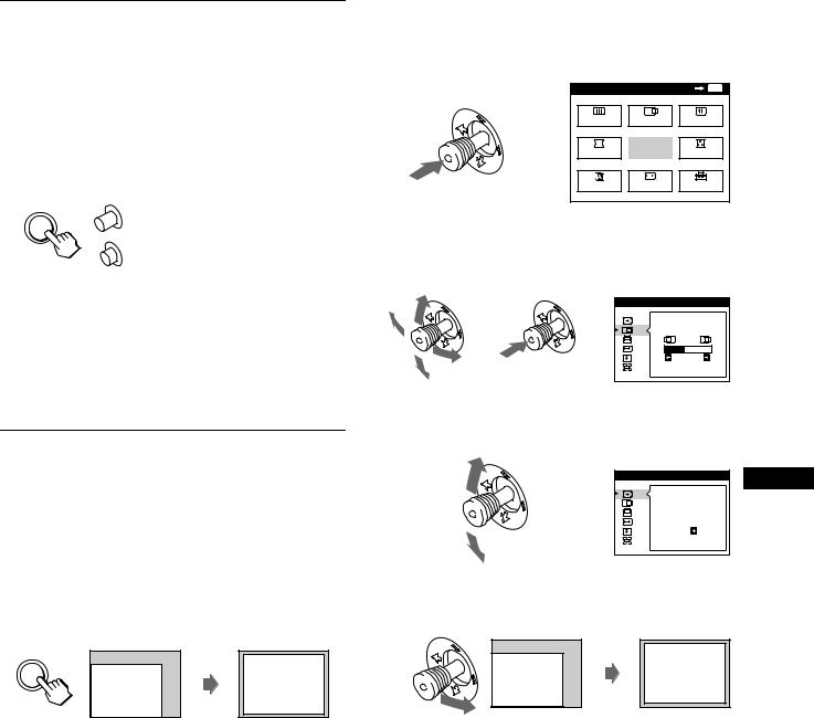
Sélection du signal d’entrée
Vous pouvez raccorder deux ordinateurs via les connecteurs HD15 et BNC. Pour commuter les deux ordinateurs, utilisez la touche INPUT.
Appuyez sur la touche INPUT.
Chaque fois que vous appuyez sur cette touche, le signal d’entrée et l’indicateur correspondant alternent.
Lorsque cette touche est enfoncée, BNC est sélectionné; lorsque cette touche n’est pas enfoncée, HD15 est sélectionné.
HD15
INPUT |
BNC |
Le connecteur sélectionné apparaît sur l’écran pendant quelques secondes. “HD15” ou “BNC” apparaît sur l’écran.
Remarque
Si aucun signal n’est entré via le connecteur sélectionné, l’indication PAS ENTREE VIDEO apparaît à l’écran. Au bout de quelques secondes, le moniteur passe en mode d’économie d’énergie. Si cela se produit, commutez l’autre connecteur.
Taille et centrage automatiques de l’image (AUTO)
Vous pouvez aisément régler l’image pour qu’elle remplisse l’écran en appuyant sur la touche ASC (taille et centrage automatiques) ou à l’aide du menu.
x A l’aide de la touche ASC
Appuyez sur la touche ASC.
L’image remplit automatiquement l’écran.
x Utilisation du menu
1Appuyez sur la manette de commande pour afficher le menu principal à l’écran.
MENU |
|
OK |
MENU |
ECRAN |
CENTRE |
CONV |
|
b |
SORTIR |
COUL. |
|
GEOM |
|||
LANG |
TAILLE |
OPTION |
|
2Déplacez la manette de commande pour mettre en évidence
 CENTRE ou
 TAILLE et appuyez de nouveau sur la manette de commande.
|
TA I L LE / CENTRE |
b |
b |
|
2 6 |
3Déplacez la manette de commande vers le haut ou le bas pour sélectionner  (AUTO).
|
TA I L LE / CENTRE |
FR |
|
|
|
b |
AUTO |
|
|
|
|
|
ON |
|
4Déplacez la manette de commande vers la droite,.
L’image remplit automatiquement l’écran.
ASC
Remarques
• Cette fonction est destinée à être utilisée sur des ordinateurs tournant sous Windows ou dotés d’un logiciel d’interface graphique utilisateur qui offre une image plein écran. Elle peut ne pas fonctionner correctement si la couleur d’arrière-plan est foncée ou si l’image d’entrée ne remplit pas l’écran jusqu’aux bords (comme une invite MSDOS).
• Les images d’un rapport de 5:4 (résolution: 1280 × 1024, 1800 × 1440) sont affichées suivant leur résolution réelle et ne remplissent pas l’écran jusqu’aux bords.
• L’image affichée se déplace pendant quelques secondes lorsque cette fonction est exécutée. Il ne s’agit pas d’un dysfonctionnement.
9
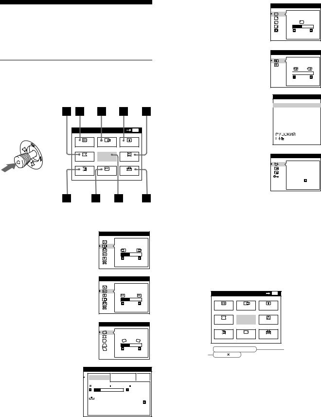
Personnalisation de votre moniteur
Vous pouvez effectuer de multiples réglages sur votre moniteur à l’aide des écrans de menu.
Pilotage par menus
Appuyez sur la manette de commande pour afficher le MENU principal à l’écran. Voir la page 11 pour plus d’informations sur l’utilisation de la manette de commande.
|
MENU |
|
OK |
MENU |
|
ECRAN |
CENTRE |
CONV |
|
b |
GEOM |
SORTIR |
COUL. |
|
|
LANG |
TAILLE |
OPTION |
|
Utilisez la manette de commande pour sélectionner l’un des menus suivants.
1CENTRE (page 12)
Sélectionne le menu CENTRE pour régler le centrage de l’image, la taille ou le zoom.
2TAILLE (page 11)
Sélectionne le menu TAILLE pour régler la taille de l’image, le centrage ou le zoom.
TA I L LE / CENTRE |
2 6 |
TA I L LE / CENTRE |
2 6
3 GEOM (page 12) |
GEOMETR I E |
Sélectionne le menu GEOM pour |
|
régler la rotation et la forme de |
|
l’image. |
2 6 |
|
4COULEUR (page 13)
Sélectionne le menu COULEUR pour régler la température de couleur de l’image. Vous pouvez utiliser ce menu pour faire correspondre les couleurs du moniteur aux couleurs d’une image imprimée.
COU L EUR |
|
|
S I MP L E |
EXPERT |
s RGB |
5 0 0 0 K 6 5 0 0 K 9 3 0 0 K |
||
|
|
5 0 0 0 K |
RES T AURER |
|
|
COU L EUR |
ON |
|
5ECRAN (page 13)
Sélectionne le menu ECRAN pour ajuster la qualité de l’image. Vous pouvez ajuster l’alignement et l’effet de suppression du moiré.
6CONV (page 12)
Sélectionne le menu CONV pour régler la convergence horizontale et verticale de l’image.
7LANG (page 8)
Sélectionne le menu LANG pour choisir la langue d’affichage des menus.
ECRAN |
PURE T E |
COU L EUR |
2 6 |
CONVERGENCE |
 TOP
TOP
 BOT
BOT 

 2 6
2 6
L ANGUAGE
 ENGL I SH
FRANÇA I S
DEUT SCH
ESPAÑOL
I T A L I ANO
NEDER L ANDS
SVENSKA
8 OPTION (page 15) |
OPT I ON |
|
Sélectionne le menu OPTION pour |
DEGAUSS |
|
régler les options du moniteur. Les |
||
|
||
options comprennent: |
ON |
|
• démagnétisation de l’écran |
||
|
||
• changement de la position des |
|
|
écrans de menu |
|
|
• verrouillage des commandes |
|
9SORTIR
Sélectionne SORTIR pour quitter le menu.
x Affichage du signal d’entrée en cours
Les fréquences horizontale et verticale du signal d’entrée en cours sont affichées dans le MENU principal. Si le signal correspond à l’un des modes présélectionnés de ce moniteur, la résolution est également affichée.
la résolution du signal d’entrée en cours
MENU |
|
|
OK |
MENU |
ECRAN |
CENTRE |
CONV |
||
GEOM |
SORTIR |
COUL. |
||
LANG |
|
TAILLE |
OPTION |
|
68 . 7kHz / 85Hz |
|
|
||
1024 |
768 |
|
|
|
les fréquences
horizontale et verticale du signal d’entrée en cours
10
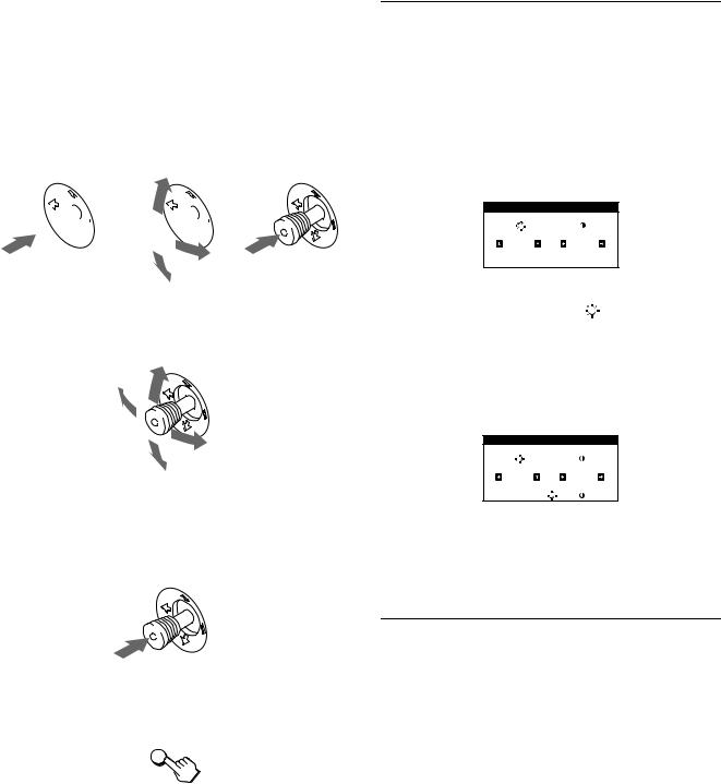
x Utilisation de la manette de commande
1Affichez le MENU principal et sélectionnez le menu que vous voulez régler.
Appuyez une fois sur la manette de commande pour afficher le MENU principal. Ensuite, déplacez la manette de commande vers le haut, le bas, la gauche ou la droite de façon à mettre en évidence le menu de votre choix. Appuyez sur la manette de commande pour sélectionner un paramètre de menu.


 b
b


 b
b
2Réglez le menu.
Déplacez la manette de commande vers le haut, le bas, la gauche ou la droite pour effectuer le réglage.
3Quittez le menu.
Appuyez une fois sur la manette de commande pour revenir au menu principal et deux fois pour revenir à la visualisation normale. Si vous n’actionnez aucune touche, le menu se referme automatiquement au bout de 30 secondes.
x Réinitialisation des réglages
Appuyez sur la touche RESET. Voir page 16 pour plus d’informations sur la réinitialisation des réglages.
RESET
Réglage de la luminosité et du contraste
Les réglages de la luminosité et du contraste sont effectués au moyen d’un menu LUMINOSITE/CONTRASTE séparé.
Ces réglages sont enregistrés dans la mémoire pour les signaux transmis via le connecteur d’entrée sélectionné.
1Déplacez la manette de commande dans n’importe quel sens.
Le menu LUMINOSITE/CONTRASTE apparaît à l’écran.
L UM I NOS I T E / CONTRAS T E
|
|
|
|
|
2 6 |
|
2 6 |
||
2 Déplacez la manette de commande vers le haut ou le bas pour régler la luminosité ( ), et vers la gauche ou la droite pour régler le contraste (6).
Si vous utilisez le mode sRGB
Si vous avez sélectionné le mode sRGB dans le menu COULEUR, le menu LUMINOSITE/CONTRASTE suivant apparaît à l’écran.
L UM I NOS I T E / CONTRAS T E
|
|
|
|
|
|
|
FR |
5 6 |
|
7 6 |
|
|
|
||
s RGB |
: |
5 6 |
7 6 |
|
|
||
Pour plus d’informations sur l’utilisation du mode sRGB, voir “Réglage des couleurs de l’image (COULEUR)” on page 13.
Le menu disparaît automatiquement au bout d’environ 3 secondes.
Réglage de la taille de l’image (TAILLE)
Ce réglage est enregistré dans la mémoire pour le signal d’entrée en cours.
1Appuyez sur la manette de commande.
Le MENU principal apparaît à l’écran.
2Déplacez la manette de commande pour mettre en évidence TAILLE et appuyez de nouveau sur la manette de commande.
Le menu TAILLE/CENTRE apparaît à l’écran.
3Déplacez d’abord la manette de commande vers le
haut ou vers le bas pour sélectionner pour le réglage horizontal, ou sur
 pour le réglage vertical. Ensuite, déplacez la manette de commande vers la gauche ou vers la droite pour ajuster les dimensions.
11
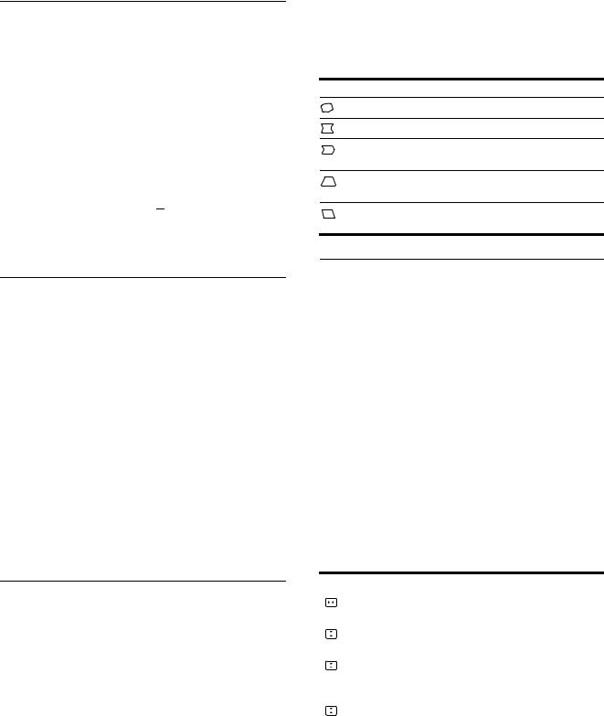
Réglage du centrage de l’image (CENTRE)
Ce réglage est enregistré dans la mémoire pour le signal d’entrée en cours.
1Appuyez sur la manette de commande.
Le MENU principal apparaît à l’écran.
2Déplacez la manette de commande pour mettre en évidence
 CENTRE et appuyez de nouveau sur la manette de commande.
Le menu TAILLE/CENTRE apparaît à l’écran.
3Déplacez d’abord la manette de commande vers le
haut ou vers le bas pour sélectionner
 pour le réglage horizontal, ou sur
 pour le réglage vertical. Ensuite, déplacez la manette de commande vers la gauche ou vers la droite pour ajuster le centrage.
Agrandir ou réduire l’image (ZOOM)
Ce réglage est enregistré dans la mémoire pour le signal d’entrée en cours.
1Appuyez sur la manette de commande.
Le MENU principal apparaît à l’écran.
2Déplacez la manette de commande pour mettre en évidence TAILLE ou
 CENTRE et appuyez de nouveau sur la manette de commande.
Le menu TAILLE/CENTRE apparaît à l’écran.
3Déplacez la manette de commande vers le haut ou vers le bas pour sélectionner 
 (zoom), puis déplacez la manette de commande vers la gauche ou vers la droite pour agrandir ou réduire l’image.
Remarque
Le réglage s’arrête lorsque la plage de réglage horizontal ou vertical atteint sa valeur limite maximum ou minimum.
Réglage de la forme de l’image (GEOM)
Les réglages GEOM vous permettent de régler la rotation et la forme de l’image.
Le réglage de la rotation est enregistré dans la mémoire pour tous les signaux d’entrée. Tous les autres réglages sont enregistrés dans la mémoire pour le signal d’entrée en cours.
1Appuyez sur la manette de commande.
Le MENU principal apparaît à l’écran.
2Déplacez la manette de commande pour mettre en évidence GEOM et appuyez de nouveau sur la manette de commande.
Le menu GEOMETRIE apparaît à l’écran.
3Déplacez d’abord la manette de commande vers le haut ou vers le bas pour sélectionner l’option de réglage désirée. Ensuite, déplacez la manette de commande vers la gauche ou vers la droite pour effectuer le réglage.
Sélectionnez Pour
faire pivoter l’image
élargir ou rétrécir les côtés de l’image
décaler les côtés de l’image vers la gauche ou la droite
régler la largeur de l’image dans le haut de l’écran
décaler l’image vers la gauche ou la droite dans le haut de l’écran
Réglage de la convergence (CONV)
Les réglages CONV vous permettent de régler la qualité de l’image en contrôlant la convergence. La convergence est l’alignement des signaux de couleur rouge, vert et bleu.
Si vous voyez des ombres rouges ou bleues autour des lettres ou des lignes, réglez la convergence.
Ces réglages sont enregistrés dans la mémoire pour tous les signaux d’entrée.
1Appuyez sur la manette de commande.
Le MENU principal apparaît à l’écran.
2Déplacez la manette de commande pour mettre en évidence CONV et appuyez de nouveau sur la manette de commande.
Le menu CONVERGENCE apparaît à l’écran.
3Déplacez d’abord la manette de commande vers le haut ou vers le bas pour sélectionner l’option de réglage désirée. Ensuite, déplacez la manette de commande vers la gauche ou vers la droite pour effectuer le réglage.
Sélectionnez |
Pour |
|||
|
|
|
|
décaler horizontalement les ombres |
|
|
|
|
|
|
|
|
|
rouges ou bleues |
|
|
|
|
|
|
|
|
|
décaler verticalement les ombres |
|
|
|
|
rouges ou bleues |
|
|
|
|
|
|
|
|
TOP |
décaler verticalement les ombres |
|
|
|
rouges ou bleues dans le haut de |
|
CONVER V HAUT |
||||
|
|
|
|
l’écran |
|
|
|
|
|
|
|
|
BOT |
décaler verticalement les ombres |
|
|
|
rouges ou bleues dans le bas de |
|
CONVER V BAS |
||||
|
|
|
|
l’écran |
|
|
|
|
|
12
 Loading...