


3-861-576-14 (1)
Trinitron Color
Graphic Display
Operating Instructions |
|
|
EN |
|||
|
|
|
|
|
|
|
Mode d’emploi |
|
F |
||||
|
|
|
|
|
||
Bedienungsanleitung |
D |
|||||
|
|
|
|
|
||
Manual de instrucciones |
|
ES |
||||
|
|
|||||
Instruzioni per l’uso |
|
I |
||||
GDM-400PST
GDM-500PST
© 1997 by Sony Corporation
Owner’s Record
The model and serial numbers are located at the rear of the unit. Record the serial number in the space provided below. Refer to these numbers whenever you call upon your dealer regarding this product.
Model No. |
|
Serial No. |
WARNING
To prevent fire or shock hazard, do not expose the unit to rain or moisture.
Dangerously high voltages are present inside the unit. Do not open the cabinet. Refer servicing to qualified personnel only.
FCC Notice
This equipment has been tested and found to comply with the limits for a Class B digital device, pursuant to Part 15 of the FCC Rules. These limits are designed to provide reasonable protection against harmful interference in a residential installation. This equipment generates, uses, and can radiate radio frequency energy and, if not installed and used in accordance with the instructions, may cause harmful interference to radio communications. However, there is no guarantee that interference will not occur in a particular installation. If this equipment does cause harmful interference to radio or television reception, which can be determined by turning the equipment off and on, the user is encouraged to try to correct the interference by one or more of the following measures:
–Reorient or relocate the receiving antenna.
–Increase the separation between the equipment and receiver.
–Connect the equipment into an outlet on a circuit different from that to which the receiver is connected.
–Consult the dealer or an experienced radio/TV technician for help. You are cautioned that any changes or modifications not expressly approved in this manual could void your authority to operate this equipment.
EN 55022 Compliance (Czech Republic Only)
This device belongs to category B devices as described in EN 55022, unless it is specifically stated that it is a category A device on the specification label. The following applies to devices in category A of EN 55022 (radius of protection up to 30 meters). The user of the device is obliged to take all steps necessary to remove sources of interference to telecommunication or other devices.
Pokud nenÌ na typovÈm tÌtku poËÌtaËe uvedeno, æe spad· do do t¯Ìdy A podle EN 55022, spad· automaticky do t¯Ìdy B podle EN 55022. Pro za¯ÌzenÌ za¯azen· do t¯Ìdy A (ochrannÈ p·smo 30m) podle EN 55022 platÌ n·sledujÌcÌ. Dojde-li k ru enÌ telekomunikaËnÌch nebo jin˝ch za¯Ìzeni, je uæivatel povinnen provÈst takov· opat¯gnÌ, aby ru enÌ odstranil.
INFORMATION
This product complies with Swedish National Council for Metrology (MPR) standards issued in December 1990 (MPR II) for very low frequency (VLF) and extremely low frequency (ELF).
INFORMATION
Ce produit est conforme aux normes du Swedish National Council for Metrology de décembre 1990 (MPR II) en ce qui concerne les fréquences très basses (VLF) et extrêmement basses (ELF).
Hinweis
Dieses Gerät erfüllt bezüglich tieffrequenter (very low frequency) und tiefstfrequenter (extremely low frequency) Strahlung die Vorschriften des „Swedish National Council for Metrology (MPR)“ vom Dezember 1990 (MPR II).
INFORMACIÓN
Este producto cumple las normas del Consejo Nacional Sueco para Metrología (MPR) emitidas en diciembre de 1990 (MPR II) para frecuencias muy bajas (VLF) y frecuencias extremadamente bajas (ELF).
Dieses Garät entspricht den folgenden europäischen EMVVorschriften für Betrieb in Wohngebieten, gewerblicher Gebleten und Leichtindustriegebieten.
EN55022/1994 Klasse B
EN50082-1/1992
EN6100-3-2/1995
Hinweise
•Aus ergonomischen Gründen wird empfohlen, die Grundfarbe Blau nicht auf dunklem Untergrund zu verwenden (schlechte Erkennbarkeit, Augenbelastung bei zu geringem Zeichenkontrast).
•Aus ergonomischen Gründen (flimmern) sollten nur Darstellungen bei Vertikalfrequenzen ab 70 Hz (ohne Zeilensprung) verwendet werden.
•Die Konvergenz des Bildes kann sich auf Grund des Magnetfeldes am Ort der Aufstellung aus der korrekten Grundeinstellung verändern. Zur Korrektur empfiehlt es sich deshalb, die Regler an der Frontseite für Konvergenz so einzustellen, daß die getrennt sichtbaren Farblinien für Rot, Grün und Blau bei z.B. der Darstellung eines Buchstabens zur Deckung (Konvergenz) gelangen.
Siehe hierzu auch die Erklärungen zu Konvergenz.
NOTICE
This notice is applicable for USA/Canada only.
If shipped to USA/Canada, install only a UL LISTED/CSA LABELLED power supply cord meeting the following specifications:
SPECIFICATIONS
Plug Type |
|
|
|
Nema-Plug 5-15p |
||||
Cord |
|
|
|
Type SVT or SJT, minimum 3 × 18 AWG |
||||
Length |
|
|
|
Maximum 15 feet |
||||
Rating |
|
|
|
Minimum 7 A, 125 V |
||||
|
|
|
|
|
|
|
|
|
|
|
|
|
|
|
|
|
|
|
|
|
|
|
|
|
|
|
|
|
|
|
|
|
|
|
|
|
|
|
|
|
|
|
|
|
|
|
|
|
|
|
|
|
|
|
|
|
|
|
|
|
|
|
|
|
|
|
|
|
|
|
|
|
|
|
|
|
|
|
|
|
|
|
|
|
|
|
|
|
|
|
|
|
|
|
|
|
|
|
2
TABLE OF CONTENTS |
|
Getting Started |
|
Precautions ........................................................................................................................... |
4 |
Identifying Parts and Controls .......................................................................................... |
5 |
Setup ...................................................................................................................................... |
6 |
Automatically Adjusting the Size and Centering of the Picture ................................... |
7 |
Selecting the On-screen Display Language ..................................................................... |
7 |
Selecting the Input Signal ................................................................................................... |
8 |
Customizing Your Monitor |
|
Adjusting the Picture Brightness and Contrast ............................................................... |
9 |
Introducing the On-screen Display System ..................................................................... |
9 |
Using the CENTER On-screen Display .......................................................................... |
10 |
Using the SIZE On-screen Display .................................................................................. |
10 |
Using the GEOM (Geometry) On-screen Display ......................................................... |
11 |
Using the ZOOM On-screen Display .............................................................................. |
12 |
Using the COLOR On-screen Display ............................................................................ |
12 |
Using the SCREEN On-screen Display ........................................................................... |
13 |
Using the OPTION On-screen Display ........................................................................... |
15 |
Using the LANG (Language) On-screen Display ......................................................... |
17 |
Resetting the Adjustments ............................................................................................... |
17 |
Technical Features |
|
Preset and User Modes ..................................................................................................... |
18 |
Power Saving Function ..................................................................................................... |
19 |
Damper Wires .................................................................................................................... |
19 |
Plug & Play ......................................................................................................................... |
19 |
Additional Information |
|
Warning Messages ............................................................................................................. |
20 |
Troubleshooting ................................................................................................................. |
20 |
Self-diagnosis Function ..................................................................................................... |
22 |
Specifications ...................................................................................................................... |
22 |
•Macintosh is a trademark licensed to Apple Computer, Inc., registered in the U.S.A. and other countries.
•Windows® and MS-DOS are registered trademarks of Microsoft Corporation in the United States and other countries.
•IBM PC/AT and VGA are registered trademarks of IBM Corporation of the U.S.A.
•VESA is a trademark of Video Electronics Standard Association.
•All other product names mentioned herein may be the trademarks or registered trademarks of their respective companies.
•Furthermore, “™” and “®" are not mentioned in each case in this manual.
EN
F
D
ES
I
3
Getting Started
Precautions
Installation
•Prevent internal heat build-up by allowing adequate air circulation. Do not place the monitor on surfaces (rugs, blankets, etc.) or near materials (curtains, draperies) that may block the ventilation holes.
•Do not install the monitor near heat sources such as radiators or air ducts, or in a place subject to direct sunlight, excessive dust, mechanical vibration or shock.
•Do not place the monitor near equipment which generates magnetism, such as a transformer or high voltage power lines.
Maintenance
•Clean the cabinet, panel and controls with a soft cloth lightly moistened with a mild detergent solution. Do not use any type of abrasive pad, scouring powder or solvent, such as alcohol or benzine.
•Do not rub, touch, or tap the surface of the screen with sharp or abrasive items such as a ballpoint pen or screwdriver. This type of contact may result in a scratched picture tube.
•Clean the screen with a soft cloth. If you use a glass cleaning liquid, do not use any type of cleaner containing an anti-static solution or similar additive as this may scratch the screen’s coating.
Transportation
When you transport this monitor for repair or shipment, use the original carton and packing materials.
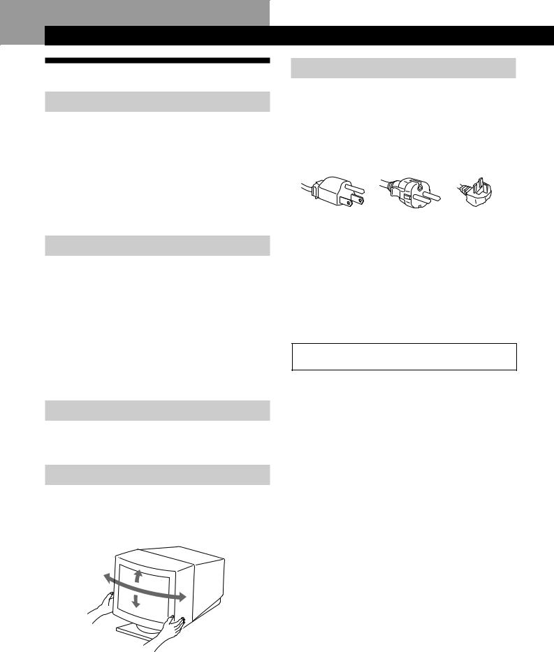
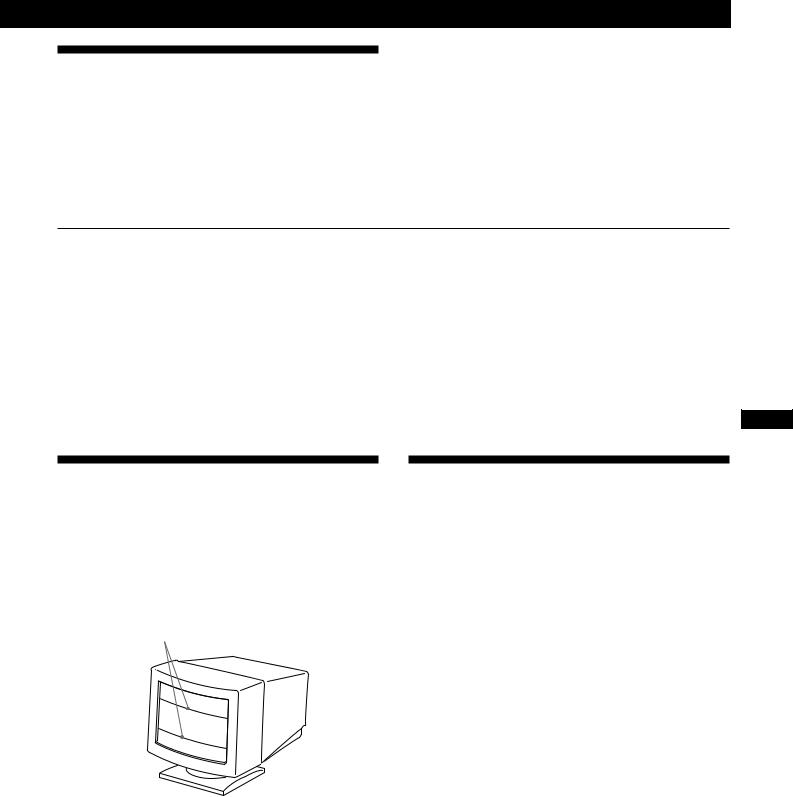
Use of the Tilt-Swivel
With the tilt-swivel, this monitor can be adjusted to the desired angle within 180° horizontally and 20° vertically. To turn the monitor vertically and horizontally, hold it at the bottom with both hands as illustrated below.
15°
90°
90°
5°
Warning on power connection
•Use an appropriate power cord for your local power supply.
For the customers in the UK
If you use the monitor in the UK, please use the supplied UK cable with the UK plug.
Examples of plug types
for 100 to 120 V AC for 200 to 240 V AC for 240 V AC only
•Before disconnecting the power cord, wait at least 30 seconds after turning off the power to allow the static electricity on the CRT display surface to discharge.
•After the power has been turned on, the CRT is demagnetized (degaussed) for about 3 seconds. This generates a strong magnetic field around the metal frame, which may affect the data stored on magnetic tapes and disks near the bezel. Place magnetic recording equipment, tapes and disks away from this monitor.
The outlet should be installed near the equipment and be easily accessible.
4
Getting Started
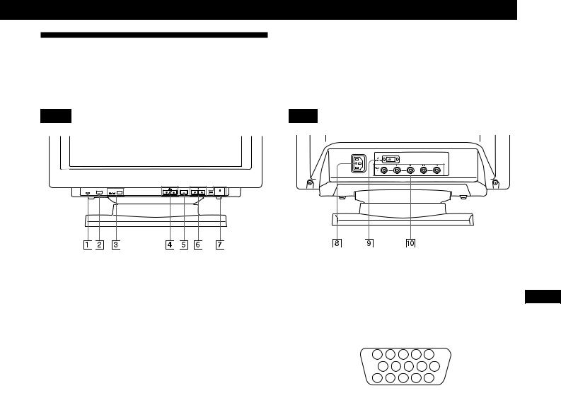
Identifying Parts and Controls
See the pages in parentheses for further details. GDM-500PST is used for illustration purposes throughout this manual.
Front |
Rear |

RESET |
HD15 BNC INPUT |
MENU |
ASC |
1RESET (reset) button (page 17)
Resets the adjustments to the factory settings.
2ASC (auto sizing and centering) button (page 7)
Automatically adjusts the size and centering of the images.
3INPUT (input) button and HD15/BNC indicators (page 8)
Selects the HD15 or 5BNC video input signal. Each time you press this button, the input signal and corresponding indicator alternate.
4 ¨ (brightness) (.>/ ) buttons (pages 8 –
17)
Adjust the picture brightness.
Function as the (./>) buttons when adjusting other items.
5MENU (menu) button (pages 8 – 17)
Displays the MENU OSD.
6> (contrast) (?//) buttons (pages 8 – 17,
22)
Adjust the contrast.
Function as the (?//) buttons when adjusting other items.
7u (power) switch and indicator (pages 19,
22)
Turns the monitor on or off.
The indicator lights up in green when the monitor is turned on, and either flashes in green and orange or lights up in orange when the monitor is in power saving mode.
8AC IN connector
Provides AC power to the monitor.
9Video input 1 connector (HD15)
Inputs RGB video signals (0.700 Vp-p, positive) and SYNC signals.
|
5 |
4 |
|
3 |
2 |
1 |
|
|
|
10 |
9 |
8 |
7 |
6 |
|
||
|
15 |
14 |
13 12 |
11 |
|
|||
|
|
|
|
|
|
|
||
Pin No. |
Signal |
|
|
|
Pin No. |
Signal |
||
1 |
Red |
|
|
|
8 |
|
|
Blue Ground |
2 |
Green |
|
|
|
9 |
|
|
DDC + 5V* |
|
(Composite |
|
|
|
10 |
|
Ground |
|
|
Sync on Green) |
|
|
|
||||
|
|
|
11 |
|
ID (Ground) |
|||
|
|
|
|
|
|
|||
3 |
Blue |
|
|
|
||||
|
|
|
12 |
|
Bi-Directional |
|||
4 |
ID (Ground) |
|
|
|
|
|||
|
|
|
|
|
|
Data (SDA)* |
||
5 |
DDC Ground* |
|
|
13 |
|
H. Sync |
||
6 |
Red Ground |
|
|
|
14 |
|
V. Sync |
|
7 |
Green Ground |
|
|
15 |
|
Data Clock(SCL)* |
||
*Display Data Channel (DDC) Standard of VESA
!º Video input 2 connector (5 BNC)
Inputs RGB video signals (0.700 Vp-p, positive) and SYNC signals.
EN
F
D
ES
I
5
Getting Started
Setup
Before using this monitor, check that the following items are included in your carton:
•Monitor (1)
•Power cord (1)
•HD15 video signal cable (1)
•Macintosh adapter (1)
•Windows 95 Monitor Information Disk/File (1)
•TCO’95 Eco-document (1)
•Warranty card (1)
•These operating instructions (1)
This monitor works with any IBM or compatible system equipped with VGA or greater graphics capability. Although this monitor works with other platforms running at horizontal frequencies between 30 and 94 kHz (GDM400PST), 30 and 107 kHz (GDM-500PST), including Macintosh and Power Macintosh systems, a cable adapter is required. Please consult your dealer for advice on which adapter is suitable for your needs.
Step 1: Connect the monitor to the
computer
With the computer switched off, connect the video signal cable to the monitor using the supplied HD15 video signal cable.
•If you are using an IBM PC/AT or compatible computer, refer to the section below.
•If you are using a Macintosh or compatible computer, refer to the following section, “Connecting to a Macintosh or compatible computer.”
•If you want to use the 5 BNC connectors, refer to the section, “Connecting to the 5 BNC connectors.”
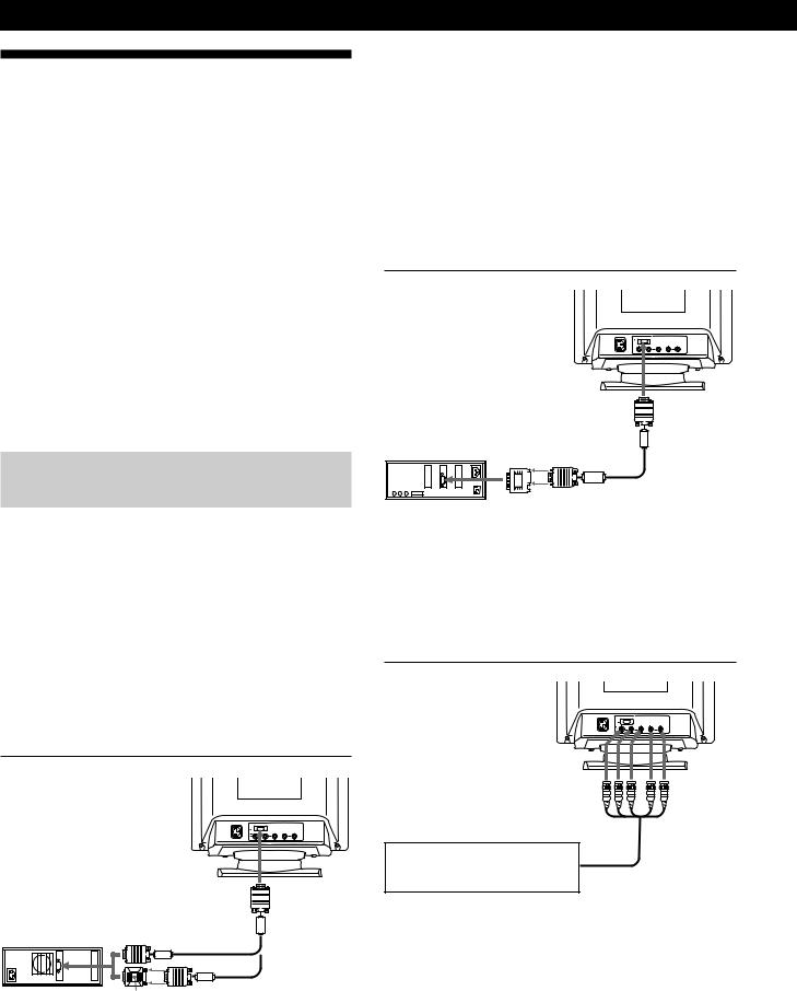
Connecting to an IBM PC/AT or compatible computer

to HD15
IBM PC/AT or |
|
compatible |
|
computer |
to video output |
HD15 video signal cable (supplied)
HD15 - HD15 adapter (not supplied)*
* The HD15 - HD15 adapter may be needed for some models.
If your PC system is not compatible with DDC2AB and DDC2B+
This monitor uses the No. 9 pin in the video signal connector for DDC2AB and DDC2B+ compatibility.
Some PC systems which are not compatible with either DDC2AB or DDC2B+ may not accept the No. 9 pin. If you are not sure whether your PC system accepts the No. 9 pin or not, use the HD15 (Female) - HD15 (Male without the No. 9 pin) adapter (not supplied). Make sure the male side (without the No. 9 pin) is connected to the computer.
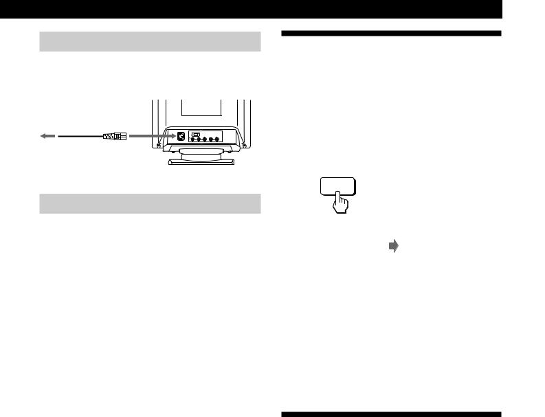
Connecting to a Macintosh or compatible computer

|
|
to HD15 |
Macintosh or |
|
|
compatible |
to video output |
|
computer |
HD15 video |
|
|
|
|
|
|
signal cable |
|
|
(supplied) |
|
Macintosh adapter |
|
|
(supplied) |
|
About the supplied Macintosh adapter
The supplied Macintosh adapter is compatible with Macintosh LC, Performa, Quadra and Power Macintosh series computers. Macintosh II series and some older versions of Power Book models may need an adapter with micro switches (not supplied).
Connecting to the 5 BNC connectors


to VIDEO IN R/G/B to SYNC IN HD/VD
Connect to the computer in the same way as for the HD15 connector.
To connect the 5 BNC connectors, use the SMF-400 video signal cable (sold separately). Connect the cables from left to right in the following order: Red–Green–Blue–HD–VD.
Notes
•Do not short the pins of the video signal cable.
•The DDC standard does not apply to the 5 BNC connectors. If you use the DDC standard, connect the HD15 connector to the computer with the supplied video signal cable.
6
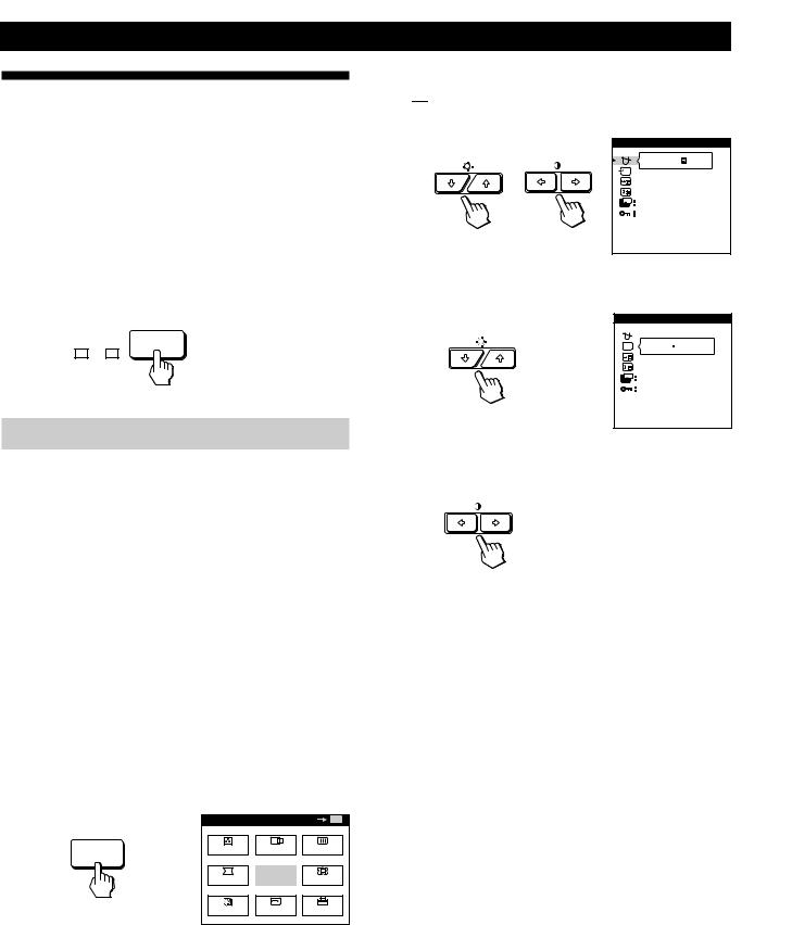
Step 2: Connect the power cord
With the monitor switched off, connect one end of the power cord to the monitor and the other end to a power outlet.
|
|
|
to a power outlet |
to AC IN |
|

Power cord (supplied)
Step 3: Turn on the monitor and computer
The installation of your monitor is complete.
Note
If “OUT OF SCAN RANGE” or “NO INPUT SIGNAL” appears on the screen, see “Warning Messages” on page 20.
For customers using Windows® 95
Install the new model information from the “Windows 95 Monitor Information Disk” into your PC. (To install the file, refer to the attached “About the Windows 95 Monitor Information Disk/File.”)
This monitor complies with the “VESA DDC” Plug&Play standard. If your PC/graphics board complies with DDC, select “Plug and Play Monitor (VESA DDC)” as “Monitor type” from “Control Panel” in Windows 95. Some PCs/graphics boards do not comply with DDC. Even if your computer complies with DDC, it may have some problems connecting with this monitor. In this case, select this monitor‘s model name (GDM-400PST or GDM-500PST) as “Monitor type” in Windows 95.
For customers using Windows NT4.0
Monitor setup in Windows NT4.0 is different from Windows 95 and does not involve the selection of monitor type. Refer to the Windows NT4.0 instruction manual for further details on adjusting the resolution, refresh rate, and number of colors.
Getting Started
Automatically Adjusting the Size
and Centering of the Picture
By pressing the auto sizing and centering (ASC) button, the size and centering of the picture are automatically adjusted to fit the screen.
1Turn on the monitor and computer.
2Press the ASC button.
The picture is adjusted to fit the center of the screen.
ASC
|
|
|
|
|
|
|
|
|
|
|
|
|
|
|
|
Notes |
|
|
|
|
|
||
EN |
|||||||
• This function is intended for use with a computer running |
|||||||
|
|||||||
Windows or similar graphic user interface software that |
|
||||||
provides a full-screen picture. It may not work properly if the |
F |
|
background color is dark or if the input picture does not fill the |
|
|
screen to the edges (such as an MS-DOS prompt). |
|
|
D |
||
• The screen may go blank for a few seconds while performing the |
|
|
auto-sizing function. This is not a malfunction. |
|
|
ES |
||
• Although the signals for picture aspect ratio 5:4 (resolution: 1280 |
||
|
||
× 1024) do not fill the screen to the edges, the picture is |
|
|
I |
||
accurately displayed. |
Selecting the On-screen Display
Language
If you need to change the OSD language, see “Using the LANG (Language) On-screen Display” on page 17.
The default setting is English.
7
Getting Started
Selecting the Input Signal
This monitor has two signal input connectors (HD15 and 5BNC) and can be connected to two computers. When the power of both computers is on, select the input signal you want to view as follows.
1Turn on the monitor and both computers.
2Press the INPUT button to select the HD15 or 5BNC input signal.
Each time you press the INPUT button, the input signal and corresponding indicator alternate.
HD15 BNC INPUT
Selecting the INPUT signal mode
This monitor has two modes of input signal selection, “AUTO” and “MANUAL.”
When “AUTO” is selected
If no signal is input from the selected connector, the monitor automatically selects the other connector’s signal. When you restart the computer you want to view, or that computer is in power saving mode, the monitor may automatically select the other connector’s signal. This is because the monitor switches from the interrupted signal to the constant signal. If this happens, manually select the desired signal using the INPUT button.
When “MANUAL” is selected
Even if no signal is input from the selected connector, the monitor does not select the other connector’s signal.
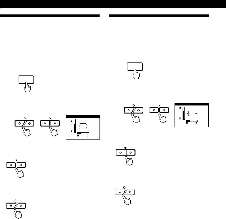
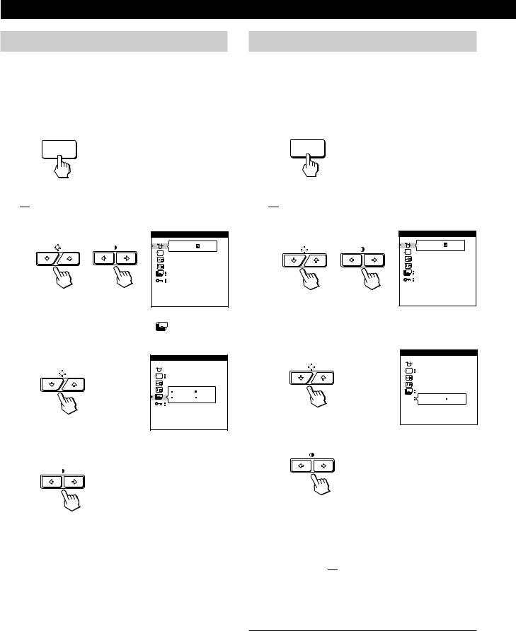
1Press the MENU button.
The MENU OSD appears.
MENU
MENU |
|
OK |
MENU |
COLOR |
CENTER SCREEN |
||
GEOM |
EXIT |
ZOOM |
|
LANG |
SIZE |
OPTION |
|
2Press the ¨./>and >?//buttons to select
“ 


 OPTION,” and press the MENU button again.
The OPTION OSD appears.
OPTION |
|
|
ON |
ZZ... |
1 MIN |
|
|
|
UNLOCK |
MANUAL DEGAUSS |
|
3 Press the ¨./>buttons to select “  (INPUT).”
OPTION


 AUTO MANUAL
ZZ... |
1 MIN |
|
|
|
UNLOCK |
|
INPUT |
4Press the >?//buttons to select “AUTO” or
“MANUAL.”
The OPTION OSD automatically disappears after about 30 seconds.
To close the OSD, press the MENU button again.
For more information on using the OSD, see “Introducing the On-screen Display System” on page 9.
8
|
|
|
|
Customizing Your Monitor |
Customizing Your Monitor |
|
|
|
Before adjusting
•Connect the monitor and the computer, and turn them on.
•Select “ 
 LANG” in the MENU OSD, then select “ENGLISH” (see page 17).
Adjusting the Picture Brightness
and Contrast
Once the setting is adjusted, it will be stored in memory for all input signals received.
1Press the ¨ (brightness) ./>or >(contrast) ?// buttons.
The BRIGHTNESS/CONTRAST OSD appears.
BRIGHTNESS/CONTRAST
26 
 26 80.0kHz/ 75Hz
Horizontal Vertical
Frequency* Frequency*
2For brightness adjustment
Press the ¨./>buttons.
>. . . for more brightness
.. . . for less brightness
For contrast adjustment
Press the >?//buttons.
/. . . for more contrast ?. . . for less contrast
The OSD automatically disappears after about 3 seconds.
To reset, press the RESET button while the OSD is on. The brightness and contrast are both reset to the factory settings.
*The horizontal and vertical frequencies for the received input signal appear in the BRIGHTNESS/CONTRAST OSD.
Introducing the On-screen
Display System
Most adjustments are made using the MENU OSD.
MENU OSD
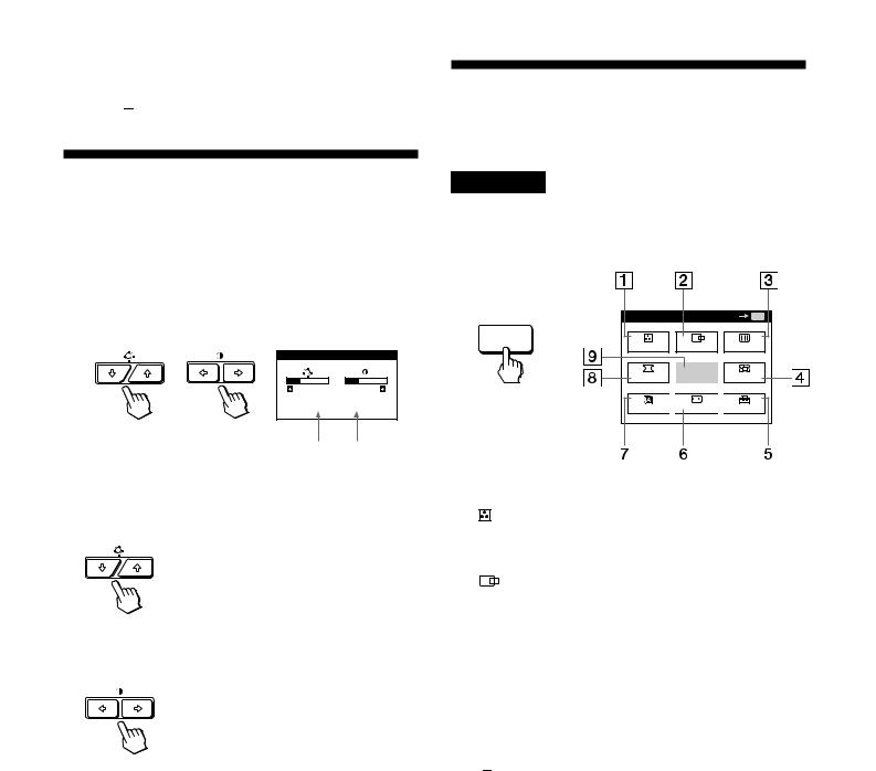
Press the MENU button to display the MENU OSD.
This MENU OSD contains links to the other OSDs described below.
MENU |
OK MENU |
MENU |
CENTER SCREEN |
COLOR |
GEOM |
EXIT |
ZOOM |
LANG 
 SIZE
SIZE 
 OPTION
|
|
|
|
|
|
|
|
|
|
|
|
|
|
|
|
|
|
|
|
|
|
|
|
|
|
|
|
EN |
|
|
|
|
|
|
|
|
|
|
|
1 |
COLOR |
F |
|||||||
|
Displays the COLOR OSD for adjusting the color |
|
|||||||
|
temperature. |
D |
|||||||
2 |
CENTER |
|
|||||||
ES |
|||||||||
|
Displays the CENTER OSD for adjusting the centering |
||||||||
|
|
||||||||
|
of the picture. |
|
|||||||
|
I |
||||||||
|
|
|
|
|
|
|
|
||
3  SCREEN
Displays the SCREEN OSD for adjusting the vertical and horizontal convergence, etc.
4  ZOOM
ZOOM
Displays the ZOOM OSD for enlarging and reducing the picture.
5 


 OPTION
Displays the OPTION OSD for adjusting the OSD position and degaussing the screen, etc.
6  SIZE
SIZE
Displays the SIZE OSD for adjusting the picture size.
7 
 LANG
LANG
Displays the LANGUAGE OSD for selecting the language.
8  GEOM
GEOM
Displays the GEOMETRY OSD for adjusting the picture rotation and pincushion, etc.
9EXIT
Closes the MENU OSD.
9
Customizing Your Monitor
Using the CENTER On-screen
Display
The CENTER settings allow you to adjust the centering of the picture.
Once the setting is adjusted, it will be stored in memory for the current input signal.
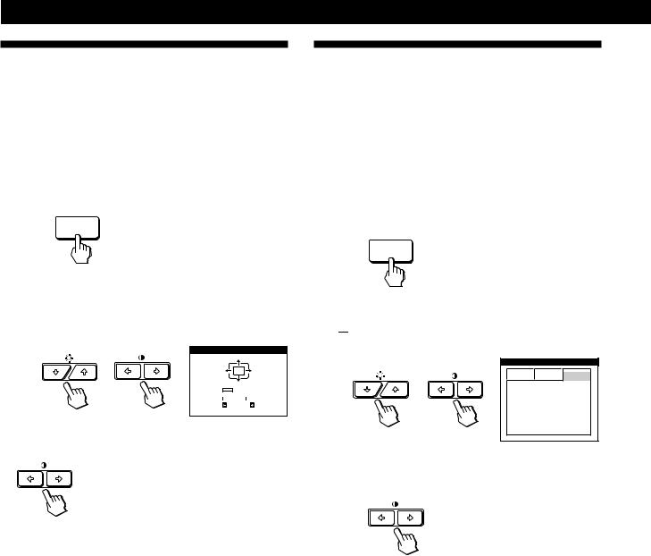
1Press the MENU button.
The MENU OSD appears.
MENU
2Press the ¨./>and >?//buttons to select
“ 
 CENTER,” and press the MENU button again.
The CENTER OSD appears.
CENTER
73
26
3For horizontal adjustment
Press the >?//buttons.
/. . . to move the picture right ?. . . to move the picture left
For vertical adjustment
Press the ¨./>buttons.
>. . . to move the picture up
.. . . to move the picture down
The OSD automatically disappears after about 30 seconds. To close the OSD, press the MENU button again.
To reset, press the RESET button while the OSD is on. The horizontal and vertical centerings are both reset to the factory settings.
Using the SIZE On-screen Display
The SIZE settings allow you to adjust the size of the picture. Once the setting is adjusted, it will be stored in memory for the current input signal.
1Press the MENU button.
The MENU OSD appears.
MENU
2Press the ¨./>and >?//buttons to select
“  SIZE,” and press the MENU button again.
The SIZE OSD appears.
SIZE
73
26
3For horizontal adjustment
Press the >?//buttons.
/. . . to increase picture size ?. . . to decrease picture size
For vertical adjustment
Press the ¨./>buttons.
>. . . to increase picture size
.. . . to decrease picture size
The OSD automatically disappears after about 30 seconds. To close the OSD, press the MENU button again.
To reset, press the RESET button while the OSD is on.
The horizontal and vertical sizes are both reset to the factory settings.
10
Using the GEOM (Geometry) Onscreen Display
The GEOM (Geometry) settings allow you to adjust the shape and orientation of the picture.
Once the rotation is adjusted, it will be stored in memory for all input signals received. All other adjustments will be stored in memory for the current input signal.
1Press the MENU button.
The MENU OSD appears.
MENU
2Press the ¨./>and >?//buttons to select
“  GEOM,” and press the MENU button again.
The GEOMETRY OSD appears.
GEOMETRY
26
ROTATION
3Press the ¨./>buttons to select the item you want to adjust.
Select |
To |
ROTATION |
adjust the picture rotation |
PINCUSHION |
adjust the picture sides |
PIN BALANCE |
adjust the picture side balance |
KEYSTONE |
adjust the picture width |
KEY BALANCE |
adjust the picture shape balance |
Customizing Your Monitor
4 Press the >?//buttons to adjust the settings.
For |
Press |
ROTATION /. . . to rotate the picture clockwise
?. . . to rotate the picture counterclockwise
PINCUSHION /. . . to expand the picture sides
?. . . to contract the picture sides
PIN BALANCE |
/. . . to move the picture sides to the right |
|
|
|
|
EN |
|||
|
|
|
|
|
|
?. . . to move the picture sides to the left |
|
||
|
F |
|||
|
|
|
|
|
|
|
|
|
D |
KEYSTONE |
/. . . to increase the picture width at the |
|
||
|
top |
ES |
||
|
|
|
|
|
|
?. . . to decrease the picture width at the |
I |
||
|
|
|||
|
top |
|
||
KEY BALANCE /. . . to move the top of the picture to the right
?. . . to move the top of the picture to the left
The OSD automatically disappears after about 30 seconds. To close the OSD, press the MENU button again.
To reset, press the RESET button while the OSD is on.
The selected item is reset to the factory setting.
11
Customizing Your Monitor
Using the ZOOM On-screen
Display
The ZOOM settings allow you to enlarge or reduce the picture.
Once the setting is adjusted, it will be stored in memory for the current input signal.
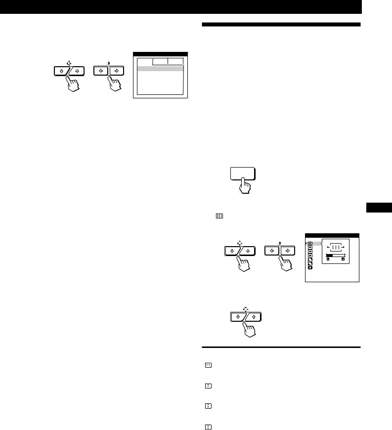
1Press the MENU button.
The MENU OSD appears.
MENU
2Press the ¨./>and >?//buttons to select
“  ZOOM,” and press the MENU button again.
The ZOOM OSD appears.
ZOOM
H |
|
|
|
|
|
|
|
|
26 |
|
|
|
|
|
|
|
|
||
V |
|
|
|
|
|
|
|
73 |
|
3 Press the >?//buttons to adjust the picture zoom.
/. . . to enlarge the picture ?. . . to reduce the picture
Using the COLOR On-screen
Display
You can change the monitor’s color temperature. For example, you can adjust or change the colors of a picture on the screen to match the actual colors of the printed picture. Once the setting is adjusted, it will be stored in memory for all input signals received.
1Press the MENU button.
The MENU OSD appears.
MENU
2Press the ¨./>and >?//buttons to select
“ 

 COLOR,” and press the MENU button again.
The COLOR OSD appears.
COLOR
5000K 6500K 9300K
R BIAS 

 50
50
G BIAS 

 50
50
B BIAS 

 50
50
R GAIN 

 50
50
G GAIN 

 50
50
B GAIN 

 50
50
3Press the >?//buttons to select the color temperature.
The OSD automatically disappears after about 30 seconds. To close the OSD, press the MENU button again.
To reset, press the RESET button while the OSD is on.
Note
The picture zoom adjustment will stop as soon as either the horizontal or vertical size reaches its maximum or minimum value.
There are three color temperature modes in the OSD. The preset adjustments are:
5000K, 6500K, 9300K
12
4Fine tuning the color temperature
Press the ¨./>buttons to select an item and adjust by pressing the >?//buttons.
COLOR
1 6500K 9300K
R BIAS 

 76
76
G BIAS 

 50
50
B BIAS 

 50
50
R GAIN 

 50
50
G GAIN 

 50
50
B GAIN 

 50
50
Select R (red), G (green), or B (blue) BIAS to adjust the black level of each color’s signal.
Select R (red), G (green), or B (blue) GAIN to adjust the white level of each color’s signal.
The “5000K,” “6500K” or “9300K” disappears and the new color settings are memorized for each of the three color modes.
The color temperature modes change as follows: 5000Kn1, 6500Kn2, 9300Kn3
The OSD automatically disappears after about 30 seconds. To close the OSD, press the MENU button again.
To reset, press the RESET button while the OSD is on. The selected item is reset to the factory settings.
Customizing Your Monitor
Using the SCREEN On-screen
Display
You can adjust convergence settings to eliminate red or blue shadows that may appear around objects on the screen. Adjust the CANCEL MOIRE function to eliminate wavy or elliptical patterns that may appear on the screen.
Adjust the LANDING function to correct color imbalances at the four corners of the screen due to influence from the earth’s magnetism.
Once CANCEL MOIRE is adjusted, it will be stored in memory for the current input signal. All other adjustments will be stored in memory for all input signals received.
1Press the MENU button.
The MENU OSD appears.
MENU
2 Press the ¨./>and >?//buttons to select |
EN |
“ SCREEN,” and press the MENU button again. |
|
The SCREEN OSD appears. |
F |
SCREEN |
D |
|
|
TOP |
|
BOT |
ES |
26 |
|
ADJ |
|
H CONVERGENCE |
I |
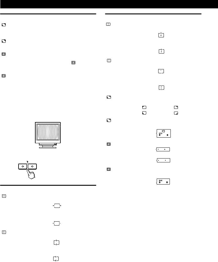
3Press the ¨./>buttons to select the item you want to adjust.
Select |
To |
||||
|
|
|
|
adjust the horizontal convergence |
|
|
|
|
|
||
H CONVERGENCE |
|
||||
|
|
|
|
|
|
|
|
|
|
adjust the vertical convergence |
|
V CONVERGENCE |
|||||
|
|||||
|
|
|
|
|
|
|
|
|
TOP |
adjust the screen’s upper vertical |
|
|
|
|
|||
V CONVER TOP |
convergence |
||||
|
|
|
|
|
|
|
|
|
BOT |
adjust the screen’s lower vertical |
|
|
|
|
|||
V CONVER BOTTOM |
convergence |
||||
|
|
|
|
|
|
|
|
|
|
(continued) |
|
13
Customizing Your Monitor
Select |
To |
|
|
select one of the four corners that |
|
LANDING |
needs color correction due to |
|
|
influence from the earth’s magnetism |
|
|
|
|
ADJ |
correct the color at one of the four |
|
LANDING ADJUST |
corners of the screen |
|
|
|
|
|
turn the moire cancellation function |
|
CANCEL MOIRE * |
“ON” or “OFF.” CANCEL MOIRE |
|
must be “ON” for “ ADJ (MOIRE |
||
|
||
|
ADJUST)” to appear on the screen. |
|
|
|
|
ADJ |
adjust the degree of moire |
|
MOIRE ADJUST |
cancellation |
|
|
|
*Moire is a type of natural interference which produces soft or wavy lines on your screen. It may appear due to interference between the regulated pattern of the picture from the input signal and the phosphor pitch pattern of the CRT.
Example of moire:
4 Press the >?//buttons to adjust the settings.
For |
Press |
|||||||||
|
|
|
|
/. . . to shift red shadows to the right |
||||||
|
|
|
|
|||||||
H CONVERGENCE |
and blue shadows to the left |
|||||||||
|
|
|
|
|
|
|
||||
|
|
|
|
|
|
|
|
|
|
|
|
|
|
|
|
|
|
|
|
|
|
|
|
|
|
?. . . to shift red shadows to the left |
||||||
|
|
|
|
and blue shadows to the right |
||||||
|
|
|
|
|
|
|
|
|
|
|
|
|
|
|
|
|
|
|
|
|
|
|
|
|
|
|
|
|
|
|
|
|
|
|
|
|
/. . . to shift red shadows up and blue |
||||||
|
|
|
|
|||||||
V CONVERGENCE |
shadows down |
|||||||||
|
|
|
|
|
|
|
||||
|
|
|
|
|
|
|
|
|
||
|
|
|
|
|
|
|
|
|
|
|
|
|
|
|
|
|
|
|
|
|
|
|
|
|
|
|
|
|
|
|
|
|
|
|
|
|
?. . . to shift red shadows down and |
||||||
|
|
|
|
blue shadows up |
||||||
|
|
|
|
|
|
|
|
|
|
|
|
|
|
|
|
|
|
|
|
|
|
|
|
|
|
|
|
|
|
|
|
|
|
|
|
|
|
|
|
|
|
|
|
|
|
|
|
|
|
|
|
|
|
|
For |
Press |
|
|
|
||||||||
|
|
|
|
TOP |
/. . . to shift red shadows up and blue |
|||||||
|
|
|
||||||||||
|
V CONVER TOP |
shadows down |
||||||||||
|
|
|
|
|
|
|
|
|
||||
|
|
|
|
|
|
|
|
|
||||
|
|
|
|
|
?. . . to shift red shadows down and |
|||||||
|
|
|
|
|
blue shadows up |
|||||||
|
|
|
|
|
|
|
|
|
|
|
||
|
|
|
|
|
|
|
|
|
|
|
|
|
|
|
|
|
BOT |
/. . . to shift red shadows up and blue |
|||||||
|
|
|
|
|||||||||
|
V CONVER BOTTOM |
shadows down |
||||||||||
|
|
|
|
|
|
|
|
|
||||
|
|
|
|
|
|
|
|
|
|
|
|
|
|
|
|
|
|
?. . . to shift red shadows down and |
|||||||
|
|
|
|
|
blue shadows up |
|||||||
|
|
|
|
|
|
|
|
|
|
|
|
|
|
|
|
|
|
|
|
|
|
|
|
||
|
|
|
|
|
/or ?. . . to select the corner of the |
|||||||
|
LANDING |
screen you want to adjust |
||||||||||
|
|
|
|
|
: top left |
|
|
: top right |
||||
|
|
|
|
|
: bottom left |
|
|
: bottom right |
||||
|
|
|
|
|
|
|
|
|
|
|
||
|
|
|
|
ADJ |
/or ?. . . to reduce any irregularities in |
|||||||
|
LANDING ADJUST |
the color to a minimum |
||||||||||
|
|
|
|
|
|
|
|
|
|
|
|
|
|
|
|
|
|
|
|
|
|
|
|
|
|
|
|
|
|
|
50 |
|
|
|
||||
|
|
|
|
|
|
|
|
|
|
|
||
|
|
|
|
|
/. . . to turn CANCEL MOIRE “ON” |
|||||||
|
CANCEL MOIRE |
OFF |
ON |
|||||||||
|
|
|
|
|
?. . . to turn CANCEL MOIRE “OFF” |
|||||||
|
|
|
|
|
|
OFF |
ON |
|||||
|
|
|
|
|
|
|
|
|
|
|
||
|
|
|
|
ADJ |
/or ?. . . to adjust the screen until the |
|||||||
|
MOIRE ADJUST |
moire is at a minimum |
||||||||||
|
|
|
|
|
|
|
|
|
|
|
|
|
|
|
|
|
|
50 |
|
|
|
||||
|
|
|
|
|
|
|
|
|
|
|
|
|
Note
The picture may become fuzzy when CANCEL MOIRE is set to “ON.”
The OSD automatically disappears after about 30 seconds. To close the OSD, press the MENU button again.
To reset, press the RESET button while the OSD is on. The selected item is reset to the factory setting.
14

Using the OPTION On-screen
Display
The OPTION OSD allows you to manually degauss the screen and adjust settings such as the OSD position and power saving delay time. It also allows you to lock the controls.
Degaussing the screen
The monitor screen is automatically degaussed (demagnetized) when the power is turned on. You can also manually degauss the monitor.
1Press the MENU button.
The MENU OSD appears.
MENU
2Press the ¨./>and >?//buttons to select
“ 


 OPTION,” and press the MENU button again.
The OPTION OSD appears.
|
OPTION |
|
|
|
ON |
|
ZZ... |
1 MIN |
|
|
|
|
|
UNLOCK |
|
MANUAL DEGAUSS |
|
3 Press the ¨./>buttons to select “ |
|
(MANUAL |
DEGAUSS).” |
|
|
4Press the > /button.
The screen is degaussed for about 3 seconds.
If you need to degauss the screen a second time, wait for at least 20 minutes before repeating the steps above.
The OPTION OSD automatically disappears after about 30 seconds.
To close the OSD, press the MENU button again.
Customizing Your Monitor
Changing the on-screen display position
You can change the OSD position (for example, when you want to adjust the picture behind the OSD).
1Press the MENU button.
The MENU OSD appears.
MENU
2Press the ¨./>and >?//buttons to select
“ 


 OPTION,” and press the MENU button again.
The OPTION OSD appears.
OPTION |
|
|
ON |
ZZ... |
1 MIN |
|
|
|
UNLOCK |
MANUAL DEGAUSS |
|
|
EN |
3 Press the ¨./>buttons to select “ |
|
(OSD H |
|
|||||
F |
||||||||
|
||||||||
POSITION)” or “ |
|
(OSD V POSITION).” |
||||||
|
|
|||||||
Select “ |
|
|
|
|
|
|||
|
(OSD H POSITION)” to adjust the horizontal |
|
||||||
D |
||||||||
|
||||||||
position. |
|
|
|
|
|
|
||
|
|
|
|
|
|
|
||
OPTION |
ES |
|
|
|
I |
ZZ... |
1 MIN |
|
|
|
UNLOCK |
OSD H POSITION
Select “  (OSD V POSITION)” to adjust the vertical position.
OPTION |
AUTO |
ZZ... |
UNLOCK |
OSD V POSITION |
4Press the >?//buttons to move the OSD to the desired position.
The OPTION OSD automatically disappears after about 30 seconds.
To close the OSD, press the MENU button again.
To reset, press the RESET button while the OSD is on. 15
Customizing Your Monitor
Setting the power saving delay time
You can set the delay time before the monitor enters the power saving mode. See page 19 for more information on this monitor’s power saving capabilities.
1Press the MENU button.
The MENU OSD appears.
MENU
2Press the ¨./>and >?//buttons to select
“ 


 OPTION,” and press the MENU button again.
The OPTION OSD appears.
Locking the controls
The control lock function disables all of the buttons on the front panel except the u(power) switch, MENU and INPUT buttons.
1Press the MENU button.
The MENU OSD appears.
MENU
2Press the ¨./>and >?//buttons to select
“ 


 OPTION,” and press the MENU button again.
The OPTION OSD appears.
OPTION |
|
|
ON |
ZZ... |
1 MIN |
|
|
|
UNLOCK |
MANUAL DEGAUSS |
|
3Press the ¨./>buttons to select “  ZZ... (PWR SAVE
DELAY).”
OPTION |
|
|
|
AUTO |
|
|
5 SEC |
1 MIN |
ZZ... |
60 MIN |
OFF |
|
||
|
PWR SAVE DELAY |
|
4 Press the >?//buttons to select the desired time.
OPTION |
|
|
ON |
ZZ... |
1 MIN |
|
|
|
UNLOCK |
MANUAL DEGAUSS |
|
3Press the ¨./>buttons to select “ (CONTROL
LOCK).”
OPTION
AUTO
ZZ...

 UNLOCK LOCK
CONTROL LOCK
4 Press the >?//buttons to select “LOCK.”
When PWR SAVE DELAY is set to “OFF,” the monitor does not go into power saving mode.
The OPTION OSD automatically disappears after about 30 seconds.
To close the OSD, press the MENU button again.
To reset, press the RESET button while the OSD is on.
The OPTION OSD automatically disappears after about 30 seconds.
To close the OSD, press the MENU button again.
Once you select “LOCK,” you cannot select any items except “EXIT” and ” 

 OPTION” in the MENU OSD. If you press any button other than the u(power) switch,
MENU and INPUT buttons, the  mark appears on the screen.
To cancel the control lock
Repeat steps 1 through 3 above and press the >?// buttons to select “UNLOCK.”
16
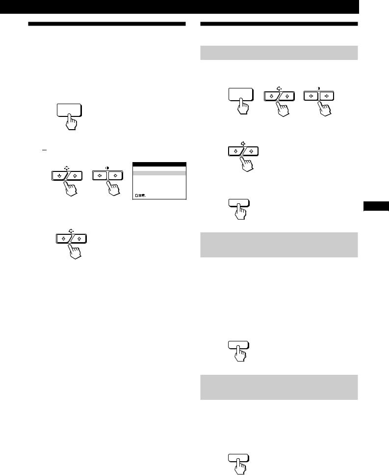
Using the LANG (Language) Onscreen Display
English, French, German, Spanish, Italian and Japanese versions of the OSDs are available.
1Press the MENU button.
The MENU OSD appears.
MENU
2Press the ¨./>and >?//buttons to select
“ 
 LANG,” and press the MENU button again.
The LANGUAGE OSD appears.
LANGUAGE
 ENGLISH
FRANÇAIS
DEUTSCH
ESPAÑOL
I TALIANO
3Press the ¨./>buttons to select the desired language.
ENGLISH: English, FRANÇAIS: French,
DEUTSCH: German, ESPAÑOL: Spanish,
ITALIANO: Italian, or 
 : Japanese.
The OSD automatically disappears after about 30 seconds. To close the OSD, press the MENU button again.
To reset to English, press the RESET button while the OSD is on.
Customizing Your Monitor
Resetting the Adjustments
Resetting an adjustment item
1Press the MENU, ¨./>and >?//buttons to select the OSD containing the item you want to reset.
MENU
2Press the ¨./>buttons to select the item you want to reset.
3 Press the RESET button.
RESET
|
EN |
|
F |
Resetting all of the adjustment data for |
D |
the current input signal |
ES |
|
When there is no OSD displayed, press the RESET
button. |
I |
All of the adjustments data for the current input signal is reset to the factory settings.
Note that adjustment data not affected by changes in input signal (OSD language, OSD position, input signal selection, power saving delay time and the control lock function) is not reset to the factory settings.
RESET
Resetting all of the adjustment data for all
input signals
Press and hold the RESET button for more than two seconds.
All of the adjustment data, including the brightness and contrast, is reset to the factory settings.
RESET
17

Technical Features
Preset and User Modes
This monitor has factory preset modes for the most popular industry standards for true “plug and play” compatibility.
When a new input signal is entered, the monitor selects the appropriate factory preset mode and momentarily adjusts the phase calibration to provide a high quality picture to the center of the screen. The calibration is stored in memory and is immediately recalled whenever the same input signal is received.
Resolution Horizontal Vertical
No. |
(dots × lines) Frequency Frequency Graphics Mode |
||||
1 |
640 × 350 |
31.5 kHz |
70 Hz |
MCGA |
|
|
|
|
|
|
|
2 |
640 × 480 |
31.5 kHz |
60 Hz |
VGA-G |
|
|
|
|
|
|
|
3 |
640 × 480 |
37.5 kHz |
75 Hz |
EVGA |
|
|
|
|
|
|
|
4 |
640 × 480 |
43.3 kHz |
85 Hz |
VESA |
|
|
|
|
|
|
|
5 |
720 × 400 |
31.5 kHz |
70 Hz |
VGA-Text |
|
|
|
|
|
|
|
6 |
720 × 400 |
37.9 kHz |
85 Hz |
VESA |
|
|
|
|
|
|
|
7 |
800 × 600 |
37.9 kHz |
60 Hz |
SVGA |
|
|
|
|
|
|
|
8 |
800 × 600 |
46.9 kHz |
75 Hz |
ESVGA |
|
|
|
|
|
|
|
9 |
800 × 600 |
53.7 kHz |
85 Hz |
VESA |
|
|
|
|
|
|
|
10 |
832 × 624 |
49.7 kHz |
75 Hz |
Macintosh |
|
|
|
|
|
|
16” Color |
|
|
|
|
|
|
11 |
1024 |
× 768 |
48.4 kHz |
60 Hz |
VESA |
|
|
|
|
|
|
12 |
1024 |
× 768 |
56.5 kHz |
70 Hz |
VESA |
|
|
|
|
|
|
13 |
1024 |
× 768 |
60.0 kHz |
75 Hz |
EUVGA |
|
|
|
|
|
|
14 |
1024 |
× 768 |
60.2 kHz |
75 Hz |
Macintosh |
|
|
|
|
|
19” Color |
|
|
|
|
|
|
15 |
1024 |
× 768 |
68.7 kHz |
85 Hz |
VESA |
|
|
|
|
|
|
16 |
1152 |
× 864 |
67.5 kHz |
75 Hz |
VESA |
|
|
|
|
|
|
17 |
1152 |
× 870 |
68.7 kHz |
75 Hz |
Macintosh |
|
|
|
|
|
21” Color |
|
|
|
|
|
|
18 |
1280 |
× 960 |
60.0 kHz |
60 Hz |
VESA |
|
|
|
|
|
|
19 |
1280 |
× 960 |
85.9 kHz |
85 Hz |
VESA |
|
|
|
|
|
|
20 |
1280 |
× 1024 |
64.0 kHz |
60 Hz |
VESA |
|
|
|
|
|
|
21 |
1280 |
× 1024 |
80.0 kHz |
75 Hz |
VESA |
|
|
|
|
|
|
22 |
1280 |
× 1024 |
91.1 kHz |
85 Hz |
VESA |
|
|
|
|
|
|
23 |
1600 |
× 1200 |
75.0 kHz |
60 Hz |
VESA |
|
|
|
|
|
|
24 |
1600 |
× 1200 |
81.3 kHz |
65 Hz |
VESA |
|
|
|
|
|
|
25 |
1600 |
× 1200 |
87.5 kHz |
70 Hz |
VESA |
|
|
|
|
|
|
26 |
1600 |
× 1200 |
93.8 kHz |
75 Hz |
VESA |
|
|
|
|
|
|
27 * |
1600 |
× 1200 |
106.3 kHz |
85 Hz |
VESA |
|
|
|
|
|
|
* GDM-500PST only
For input signals that do not match one of the factory preset modes, the digital Multiscan technology of this monitor performs all of the adjustments necessary to ensure that a clear picture appears on the screen for any timing in the monitor’s frequency range. However, it may be necessary to fine tune the vertical/horizontal size and centering. Simply press the ASC button or adjust the monitor according to the adjustment instructions. The adjustments are stored automatically as a user mode and recalled whenever the corresponding input signal is received. A total of 15 user adjusted modes can be stored in memory, including those made with the ASC button. If a 16th mode is entered, it will replace the first.
Recommended horizontal and vertical timing conditions
Horizontal sync width duty should be: >4.8% of total horizontal time.
Horizontal blanking width should be: >2.5 µsec. Vertical blanking width should be: > 450 µsec.
Note for Windows® users
For Windows users, check your video board manual or the utility program which comes with your graphic board and select the highest available refresh rate to maximize monitor performance.
Adjusting the monitor’s resolution and color number
If you are using Windows 95, adjust the monitor’s resolution and color number according to the steps below. Refer also to the Windows 95 HELP files.
If you are using a Macintosh or compatible computer, Refer to your computer’s instruction manual.
1Click the Start button and point to Settings. Then double-click the Control Panel.
2Double-click the Display icon.
3Click Settings.
4Click the Color palette. Point to the desired color number and click.
Point to the Desktop area and drag the slider to the desired resolution.
5Click OK.
Note
Some settings may require that the computer be turned off then back on to take effect. In this case, follow the on-screen instructions.
About the color number
•The Color palette setting and the actual number of colors is as
follows:
High Color (16 bit) n 65,536 colors
True Color (24 bit) n about 1,677 million colors
•In True color mode (24 bit), speed may be slower.
•The color number may vary according to your computer or video board.
18
Power Saving Function
This monitor meets the power-saving guidelines set by VESA and Energy Star, as well as the more stringent NUTEK .
If the monitor is connected to a computer or video graphics board that is VESA DPMS (Display Power Management Signaling) compliant, the monitor will automatically reduce power consumption in three stages as shown below.
Technical Features
You can set the delay time before the monitor enters the power saving mode using the OSD. Set the time according to “Setting the power saving delay time” on page 16.
Note
If no video signal is input to the monitor, the “NO INPUT SIGNAL” message (page 20) appears. After the delay time has passed, the power saving function automatically puts the monitor into the active-off mode and the uindicator lights up orange. Once the horizontal and vertical sync signals are detected, the monitor automatically resumes its normal operation mode.
|
Power consumption |
Screen |
Horizontal |
Vertical |
Power consumption |
Recovery time |
u indicator |
|
mode |
|
sync signal |
sync signal |
|
|
|
|
|
|
|
|
|
|
|
1 |
Normal operation |
active |
present |
present |
≤ 160 W (GDM-500PST) |
— |
Green |
|
|
|
|
|
≤ 130 W (GDM-400PST) |
|
|
2 |
Standby (1st mode) |
blank |
absent |
present |
≤ 100 W (GDM-500PST) |
Approx. 3 sec. |
Green and orange |
|
|
|
|
|
≤ 85 W (GDM-400PST) |
|
alternate |
3 |
Suspend (2nd mode) |
blank |
present |
absent |
≤ 15 W |
Approx. 3 sec. |
Green and orange |
|
|
|
|
|
|
|
alternate |
|
|
|
|
|
|
|
|
4 |
Active-off (3rd mode) |
blank |
absent |
absent |
≤ 5 W |
Approx. 10 sec. |
Orange |
5 |
Power-off |
–– |
–– |
–– |
0 W |
— |
Off |
Damper Wires
When viewing a white background, very thin horizontal lines may be visible on the screen as shown below. These lines are the shadows of the damper wires and are characteristic of CRTs that use aperture grilles. The wires are attached to the aperture grille on the inside of the Trinitron tube and prevent the vibration of the aperture grille.
Damper wires
Plug & Play
This monitor complies with the DDC 1, DDC2B, DDC2AB and DDC2B+ Display Data Channel (DDC) standards of VESA.
When a DDC1 host system is connected, the monitor synchronizes with the V. CLK in accordance with the VESA standards and outputs the EDID (Extended Display Identification Data) to the data line.
When a DDC2B, DDC2AB or DDC2B+ host system is connected, the monitor automatically switches to the appropriate standard.
DDC is a trademark of the Video Electronics Standard Association.
Note
When using Windows® 95, the DDC standard does not apply to the 5 BNC connectors. If you use the DDC standard, connect the HD15 connector to the computer with the supplied video signal cable.
EN
F
D
ES
I
19

Additional Information
Warning Messages
If there is something wrong with the input signal, one of the following messages appears.
 INFORMATION

 OUT OF SCAN RANGE

 INPUT : HD15
1The input signal condition
“OUT OF SCAN RANGE” indicates that the input signal is not supported by the monitor’s specifications.
“NO INPUT SIGNAL” indicates that no signal is input, or the input signal from the selected input connector is not received.
2The selected input connector
Indicates which input connector is receiving the wrong signal. If there is something wrong with the signal from both input connectors, “HD15” and “BNC” are displayed alternately.
To solve these problems, see “Troubleshooting” below.
Troubleshooting
This section may help you isolate the cause of a problem and as a result, eliminate the need to contact technical support.
Symptom |
Check these items |
|
|
|
|
No picture |
|
|
|
|
|
|
If the uindicator is not lit |
• Check that the power cord is properly connected. |
|
|
• Check that the u (power) switch is in the “on” position. |
|
|
|
|
If the “NO INPUT SIGNAL” |
• The screen is blank when the monitor is in power saving mode. Try pressing any key on the |
|
message appears on the screen, |
computer keyboard. |
|
or if the uindicator is either |
• Check that your computer power switch is in the “on” position. |
|
orange or alternating between |
• Check that the input select setting is correct. |
|
green and orange |
• Check that the video signal cable is properly connected and all plugs are firmly seated in |
|
|
their sockets. |
|
|
• Check that the 5 BNCs are connected in the correct order (from left to right: Red–Green– |
|
|
Blue–HD–VD) (page 6). |
|
|
• Ensure that no pins are bent or pushed in the HD15 video input connector. |
|
|
• Check that the video board is completely seated in the proper bus slot. |
|
|
|
|
If the “OUT OF SCAN RANGE” |
• Check that the video frequency range is within that specified for the monitor. |
|
message appears on the screen |
Horizontal: 30 – 94 kHz (GDM-400PST), 30 – 107 kHz (GDM-500PST) |
|
|
Vertical: 48 – 160 Hz |
|
|
Refer to your computer‘s instruction manual to adjust the video frequency range. |
|
|
• If you are using a video signal cable adapter, check that it is correct. |
|
|
|
|
If no message is displayed and |
• See “Self-diagnosis Function” (page 22). |
|
the uindicator is green or |
|
|
flashing orange |
|
|
|
|
|
If using a Macintosh system |
• Check that the Macintosh adapter and the video signal cable are properly connected |
|
|
(page 6). |
|
|
|
|
If using Windows 95 |
• If you cannot find your model’s name (GDM-400PST or GDM-500PST) among the Sony |
|
|
monitors in the Windows 95 monitor selection screen, select the DDC standard monitor or |
|
|
install the Windows 95 Monitor Information Disk (page 7). |
|
|
The DDC standard does not apply to the 5 BNC connectors. If you use the DDC standard, |
|
|
connect the computer to the HD15 connector with the supplied video signal cable. |
|
|
|
Picture is scrambled |
• Check your graphics board manual for the proper monitor setting. |
|
|
|
• Check this manual and confirm that the graphics mode and the frequency you are trying to |
|
|
operate at is supported. Even if the frequency is within the proper range, some video |
|
|
boards may have a sync pulse that is too narrow for the monitor to sync correctly. |
|
|
|
20
Additional Information
Symptom |
Check these items |
|
|
Color is not uniform |
• Degauss the monitor (page 15). |
|
If you place equipment which generates a magnetic field, such as a loudspeaker, near the |
|
monitor, or you change the direction of the monitor, color may lose uniformity. |
|
The degauss function demagnetizes the metal frame of the CRT to obtain a neutral field for |
|
uniform color reproduction. If a second degauss cycle is needed, allow a minimum interval |
|
of 20 minutes for the best result. |
|
• Adjust the landing (pages 13 – 14). |
|
|
You cannot adjust the monitor |
• If the control lock function is set to on, set it to off using the OPTION OSD (page 16). |
with the buttons on the front |
|
panel |
|
|
|
White does not look white |
• Adjust the color temperature (page 12 - 13). |
|
• Check that the 5 BNCs are connected in the correct order (from left to right: Red–Green– |
|
Blue–HD–VD) (page 6). |
|
|
Screen image is not centered or |
• Press the ASC button (page 7). |
sized properly |
• Adjust the size or centering (page 10). |
|
• Some video modes do not fill the screen to the edges. This problem tends to occur with |
|
certain video boards. |
|
|
Edges of the image are curved |
• Adjust the geometry (page 11). |
|
|
White lines show red or blue |
• Adjust the convergence (pages 13 – 14). |
shadows at edges |
|
|
|
Picture is fuzzy |
• Adjust the contrast and brightness (page 9). |
|
• Degauss the monitor (page 15). |
|
If you place equipment which generates a magnetic field, such as a loudspeaker, near the |
|
monitor, or you change the direction of the monitor, color may lose uniformity. |
|
The degauss function demagnetizes the metal frame of the CRT to obtain a neutral field for |
|
uniform color reproduction. If a second degauss cycle is needed, allow a minimum interval |
|
of 20 minutes for the best result. |
|
• If red or blue shadows appear along the edges of images, adjust the convergence |
|
(pages 13 – 14). |
|
• If the moire is cancelled, the picture may become fuzzy. Decrease the moire cancellation |
|
effect (pages 13 – 14). |
|
|
Picture bounces or has wavy |
• Isolate and eliminate any potential sources of electric or magnetic fields. Common causes |
oscillations |
for this symptom are electric fans, fluorescent lighting or laser printers. |
|
• If you have another monitor close to this monitor, increase the distance between them to |
|
reduce the interference. |
|
• Try plugging the monitor into a different AC outlet, preferably on a different circuit. |
|
• Try the monitor on a different computer in a different room. |
|
|
Picture is flickering |
• Set the refresh rate on the computer to obtain the best possible picture by referring to the |
|
computer’s manual. |
|
|
Picture appears to be ghosting |
• Eliminate the use of video cable extensions and/or video switch boxes if this symptom |
|
occurs. Excessive cable length or a weak connection can produce this symptom. |
|
|
Wavy or elliptical (moire) |
• Cancel the moire (pages 13 – 14). |
pattern is visible |
The moire may be modified depending on the connected computer. |
|
• Due to the relationship between resolution, monitor dot pitch and the pitch of some image |
|
patterns, certain screen backgrounds sometimes show moire. Change your desktop pattern. |
|
|
Two fine horizontal lines |
• These wires stabilize the vertically striped aperture grille (page 19). This aperture grille |
(wires) are visible |
allows more light to pass through to the screen giving the Trinitron CRT more color and |
|
brightness. |
|
|
Hum is heard right after the |
• When the power is turned on, the auto-degauss cycle is activated. While the auto-degauss |
power is turned on |
cycle is activated (3 seconds), a hum may be heard. The same hum is heard when the |
|
monitor is manually degaussed. This is not a malfunction. |
|
|
EN
F
D
ES
I
21
Additional Information
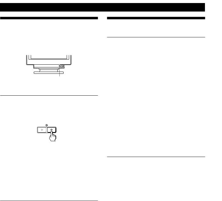
Self-diagnosis Function
This monitor is equipped with a self-diagnosis function. If there is a problem with your monitor or computer(s), the screen will go blank and the uindicator will either light up green or flash orange.
u indicator
If the u indicator is green
1Remove any plugs from the video input 1 and 2 connectors, or turn off the connected computer(s).
2Press and hold the >/button for 2 seconds.
If all four color bars appear (white, red, green, blue), the monitor is working properly. Reconnect the video input cables and check the condition of your computer(s).
If the color bars do not appear, there is a potential monitor failure. Inform your authorized Sony dealer of the monitor’s condition.
If the u indicator is flashing orange
Press the u button to turn the monitor off and on.
If the uindicator lights up green, the monitor is working properly.
If the uindicator is still flashing, there is a potential monitor failure. Count the number of seconds between orange flashes of the uindicator and inform your authorized Sony dealer of the monitor’s condition. Be sure to note the model name and serial number of your monitor. Also note the make and model of your computer and video board.
Specifications
GDM-400PST
Picture tube |
0.25 – 0.27 mm aperture grille pitch |
|
19 inches measured diagonally |
|
90-degree deflection |
Viewable image size |
Approx. 365 × 273 mm (w/h) |
|
(14 3/8 × 10 3/4 inches) |
|
18.0” viewing image |
Resolution |
Horizontal: Max. 1600 dots |
|
Vertical: Max. 1200 lines |
Standard image area |
Approx. 330 × 264 mm (w/h) |
|
(13 × 10 1/2 inches) |
|
or |
|
Approx. 352 × 264 mm (w/h) |
|
(13 7/8 × 10 1/2 inches) |
Deflection frequency |
Horizontal: 30 to 94 kHz |
|
Vertical: 48 to 160 Hz |
AC input voltage/current |
|
|
100 to 240 V, 50 – 60 Hz, 1.8 – 1.0 A |
Power consumption |
Max. 130 W |
Dimensions |
444 × 467 × 453 mm (w/h/d) |
|
(17 1/2 × 18 1/2 × 17 7/8 inches) |
Mass |
Approx. 25 kg (55 lb 2 oz) |
Supplied accessories |
See page 6 |
GDM-500PST
Picture tube |
0.25 – 0.27 mm aperture grille pitch |
|
21 inches measured diagonally |
|
90-degree deflection |
Viewable image size |
Approx. 403.8 × 302.2 mm (w/h) |
|
(16 × 12 inches) |
|
19.8” viewing image |
Resolution |
Horizontal: Max. 1600 dots |
|
Vertical: Max. 1200 lines |
Standard image area |
Approx. 388 × 291 mm (w/h) |
|
(15 3/8 × 11 1/2 inches) |
|
or |
|
Approx. 364 × 291 mm (w/h) |
|
(14 3/8 × 11 1/2 inches) |
Deflection frequency |
Horizontal: 30 to 107 kHz |
|
Vertical: 48 to 160 Hz |
AC input voltage/current |
|
|
100 to 240 V, 50 – 60 Hz, 2.0 – 1.0 A |
Power consumption |
Max. 160 W |
Dimensions |
498 × 505 × 474 mm (w/h/d) |
|
(19 5/8 × 20 × 18 3/4 inches) |
Mass |
Approx. 31 kg (68 lb 5 oz) |
Supplied accessories |
See page 6 |
Design and specifications are subject to change without notice.
22

TABLE DES MATIERES
Préparation
Précautions ........................................................................................................................... |
4 |
Identification des composants et des commandes .......................................................... |
5 |
Installation ............................................................................................................................ |
6 |
Réglage automatique de la taille et du centrage de l’image .......................................... |
7 |
Sélection de la langue d’affichage des menus ................................................................. |
7 |
Sélection du signal d’entrée ............................................................................................... |
8 |
Personnalisation de l’affichage
Réglage de la luminosité et du contraste de l’image ...................................................... |
9 |
|
Présentation du système d’écrans de menu ..................................................................... |
9 |
|
Utilisation de l’écran de menu CENTRE (centrage) ..................................................... |
10 |
|
Utilisation de l’écran de menu TAILLE .......................................................................... |
10 |
|
Utilisation de l’écran de menu GEOM (géométrie) ...................................................... |
11 |
|
Utilisation de l’écran de menu ZOOM ........................................................................... |
12 |
|
Utilisation de l’écran de menu COUL. (couleur) .......................................................... |
12 |
|
Utilisation de l’écran de menu ECRAN ......................................................................... |
13 |
|
Utilisation de l’écran de menu OPTION ........................................................................ |
15 |
|
Utilisation de l’écran de menu LANG (langue d’affichage) |
17 |
|
F |
||
.............................................................................................Réinitialisation des réglages |
17 |
|
Caractéristiques techniques
Modes présélectionné et utilisateur ................................................................................ |
18 |
Fonction d’économie d’énergie ........................................................................................ |
19 |
Fils d’amortissement ......................................................................................................... |
19 |
Un moniteur prêt à l’emploi (“Plug & Play”) ................................................................ |
19 |
Informations complémentaires
Messages d’avertissement ................................................................................................ |
20 |
Guide de dépannage ......................................................................................................... |
20 |
Fonction d’autodiagnostic ................................................................................................ |
22 |
Spécifications ...................................................................................................................... |
22 |
|
|
• Macintosh est une marque de commerce de Apple Computer, Inc., |
|
déposée aux Etats-unis et dans d’autres pays. |
|
• Windows et MS-DOS sont des marques de commerce de Microsoft |
|
Corporation déposées aux Etats-Unis et dans d’autres pays. |
|
• IBM PC/AT et VGA sont des marques de commerce de IBM |
|
Corporation déposées aux Etats-Unis. |
|
• VESA est une marque de commerce de Video Electronics Standard |
|
Association. |
|
• Tous les autres noms de produits mentionnés dans ce mode d’emploi |
|
sont des marques de commerce ou des marques déposées de leur |
|
détenteurs respectifs. |
|
• Par ailleurs, “ ” et “ ” ne sont pas repris à chaque fois dans le mode |
|
d’emploi. |
|
|
3 |
|
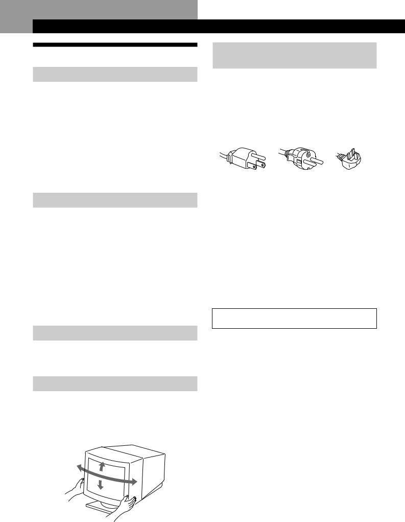
Préparation
Précautions
Installation
•Veillez à assurer une circulation d’air adéquate pour éviter une surchauffe interne de l’appareil. Ne placez pas le moniteur sur des surfaces textiles (tapis, couvertures, etc.) ni à proximité de rideaux ou de draperies susceptibles d’obstruer les orifices de ventilation.
•N’installez pas le moniteur à proximité de sources de chaleur comme un radiateur ou une bouche d’air chaud, ni dans un endroit exposé au rayonnement solaire direct, à des poussières en excès, à des vibrations ou à des chocs mécaniques.
•N’installez pas le moniteur à proximité d’équipements qui génèrent un champ magnétique tels un convertisseur ou des lignes à haute tension.
Entretien
•Nettoyez le châssis, le panneau et les commandes à l’aide d’un chiffon doux légèrement imprégné d’une solution détergente neutre. N’utilisez jamais de tampons abrasifs, de poudre à récurer ou de solvants tels que de l’alcool ou du benzine.
•Ne frottez pas, ne touchez pas et ne tapotez pas la surface de l’écran avec des objets abrasifs ou aux arêtes vives comme un stylo à bille ou un tournevis. Ce type de contact risque en effet de rayer le tube image.
•Nettoyez l’écran à l’aide d’un chiffon doux. Si vous utilisez un nettoyant liquide pour vitres, veillez à n’utiliser aucun type de produit contenant une solution antistatique ni d’additifs similaires, car ils risqueraient de rayer la couche de revêtement de l’écran.
Transport
Pour transporter ce moniteur en vue de réparations ou de son expédition, utilisez le carton d’emballage et les matériaux de conditionnement d’origine.
Utilisation du support pivotant
Le support pivotant permet de régler ce moniteur suivant l’angle de vision de votre préférence dans une plage de 180° horizontalement et 20° verticalement.
Pour faire pivoter le moniteur verticalement et horizontalement, maintenez-le des deux mains par la base comme illustré ci-dessous.
15°
90°
90°
5°
Avertissement sur le raccordement à la
source d’alimentation
•Utilisez un cordon d’alimentation convenant à votre alimentation secteur locale.
Pour les clients au Royaume-Uni
Si vous utilisez ce moniteur au Royaume-Uni, utilisez le cordon et la fiche pour le Royaume-Uni, utilisez le cordon et la fiche pour le Royaume-Uni fournis.
Modèles de fiches :
pour 100 à 120 V CA pour 200 à 240 V CA pour 240 V CA uniquement
•Avant de débrancher le cordon d’alimentation, attendez au moins 30 secondes après avoir actionné le commutateur d’alimentation de manière à permettre la décharge de l’électricité statique à la surface de l’écran à tube cathodique (CRT).
•Après que le courant a été branché, le CRT est démagnétisé pendant environ 3 secondes. Cela génère un puissant champ magnétique autour de l’encadrement métallique qui peut affecter les données mémorisées sur une bande magnétique ou des disquettes situées à proximité. Placez ces systèmes d’enregistrement magnétique et ces bandes/disquettes à l’écart de ce moniteur.
La prise murale doit être installée à proximité de l’équipement et être aisément accessible.
4
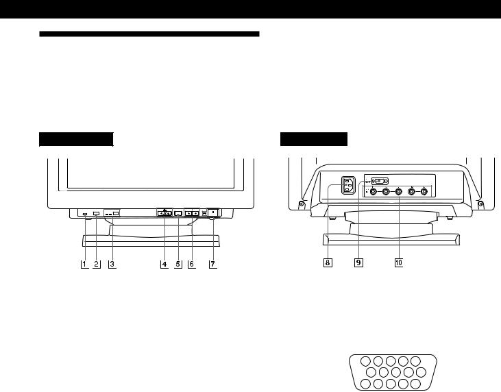
Préparation
Identification des composants et des commandes
Pour plus de détails, reportez-vous aux pages indiquées entre parenthèses.
C’est le modèle GDM-500PST qui est représenté dans les illustrations de ce mode d’emploi.
Partie frontale |
Partie arrière |

RESET |
HD15 BNC INPUT |
MENU |
ASC |
1Touche RESET (réinitialisation) (page 17)
Réinitialise les réglages aux valeurs par défaut.
2Touche ASC (taille et centrage automatiques) (page 7)
Ajuste automatiquement la taille et le centrage des images.
3Touche INPUT (entrée) et indicateurs HD15/ BNC (page 8)
Sélectionne le signal d’entrée vidéo HD15 ou 5BNC. Chaque fois que vous appuyez sur cette touche, le signal d’entrée et l’indicateur correspondant alternent.
4Touches ¨ (luminosité) (./>) (pages 8 – 17)
Règlent la luminosité de l’image.
Servent de touches (./>) pour le réglage d’autres paramètres.
5Touche MENU (menu) (page 8 – 17)
Affiche l’écran MENU.
6Touches > (contraste) (?//) (pages 8 – 17,
22)
Règlent le contraste de l’image.
Servent de touches (?//) pour le réglage d’autres paramètres.
7Commutateur et indicateur d’alimentation u (pages 19, 22)
Met le moniteur sous et hors tension.
L’indicateur s’allume en vert lorsque le moniteur est sous tension et clignote en vert et orange ou s’allume en orange lorsque le moniteur se trouve en mode d’économie d’énergie.
8 Connecteur AC IN
Assure l’alimentation du moniteur.
9 Connecteur d’entrée vidéo 1 (HD15) |
F |
|
|
Entrée des signaux vidéo RVB (0,700 Vcc, positif) et des |
|
signaux SYNC. |
|
|
5 |
4 |
|
3 |
2 |
1 |
|
|
|
10 |
9 |
8 |
7 |
6 |
|
||
|
15 |
14 |
13 12 |
11 |
|
|||
|
|
|
|
|
|
|
||
Broche n° |
Signal |
|
|
|
Broche n° |
Signal |
||
1 |
Rouge |
|
|
|
9 |
|
|
DDC + 5V* |
2 |
Vert |
|
|
|
10 |
|
|
Masse |
|
(synchronisation |
|
11 |
|
|
ID (Masse) |
||
|
composite |
|
|
|
|
|
||
|
|
|
|
12 |
|
|
Données |
|
|
sur le vert) |
|
|
|
|
|
||
|
|
|
|
|
|
|
bidirectionnelles |
|
3 |
Bleu |
|
|
|
|
|
|
|
|
|
|
|
|
|
(SDA)* |
||
4 |
ID (Masse) |
|
|
|
13 |
|
|
Sync H |
5 |
Masse DDC* |
|
|
14 |
|
|
Sync V |
|
6 |
Masse rouge |
|
|
15 |
|
|
Données |
|
7 |
Masse vert |
|
|
|
|
|
|
d’horloge |
|
|
|
|
|
|
(SCL)* |
||
8 |
Masse bleu |
|
|
|
|
|
|
|
|
|
|
|
|
|
|
||
*Norme Display Data Channel (DDC) de VESA
!º Connecteur d’entrée vidéo 2 (5 BNC)
Entrée des signaux vidéo RVB (0,700 Vcc, positif) et des signaux SYNC.
5
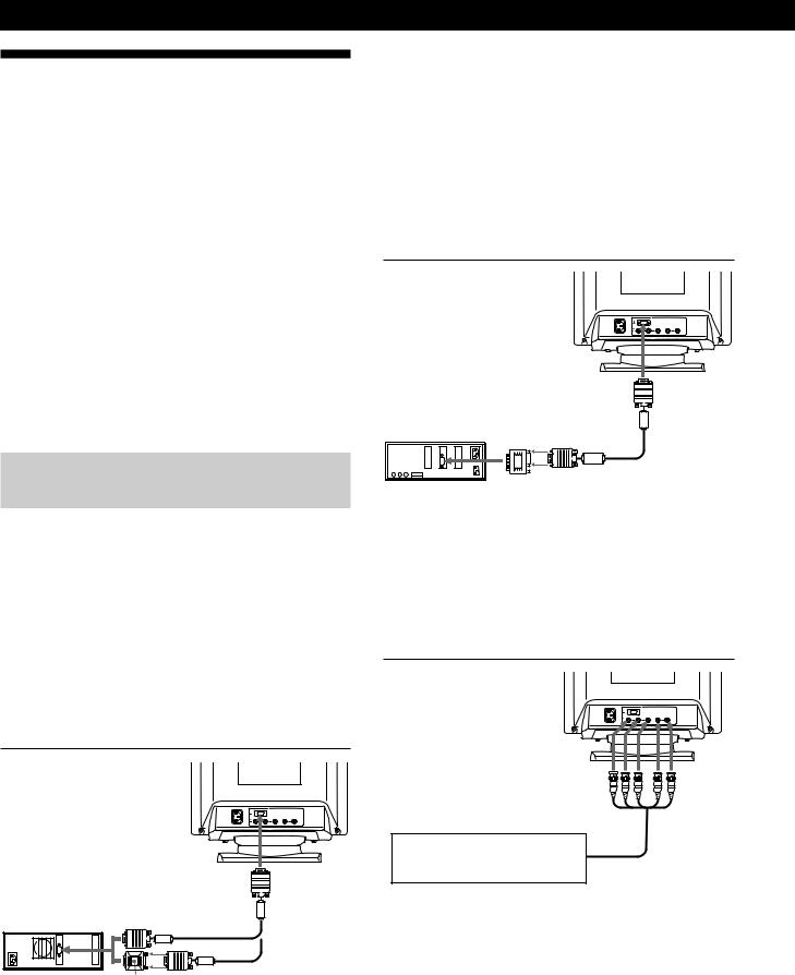
Préparation
Installation
Avant de mettre ce moniteur en service, vérifiez si tous les accessoires suivants se trouvent bien dans le carton :
•Moniteur (1)
•Cordon d’alimentation (1)
•Câble de signal vidéo HD15 (1)
•Adaptateur Macintosh (1)
•Windows 95 Monitor Information Disk/File (1)
•TCO’95 Eco-document (1)
•Carte de garantie (1)
•Ce mode d’emploi (1)
Ce moniteur fonctionne avec n’importe quel système IBM ou compatible doté d’une capacité graphique VGA ou supérieure. Bien que ce moniteur fonctionne avec d’autres plates-formes tournant à des fréquences horizontales comprises entre 30 et 94 kHz (GDM-400PST), 30 et 107 kHz (GDM-500PST), y compris des systèmes Macintosh et Power Macintosh, un adaptateur de câble est nécessaire. Veuillez consulter votre revendeur pour des conseils sur l’adaptateur correspondant à vos besoins.
1re étape: Raccordez le moniteur à
l’ordinateur
L’ordinateur étant hors tension, raccordez le câble de signal vidéo HD15 fourni au moniteur.
•Si vous utilisez un PC/AT IBM ou un ordinateur compatible, reportez-vous à la section ci-dessous.
•Si vous utilisez un Macintosh ou un ordinateur compatible, reportez-vous à la section “Raccordement à un Macintosh ou un ordinateur compatible” ci-après.
•Si vous voulez utiliser les 5 connecteurs BNC, reportezvous à la section “Raccordement aux 5 connecteurs BNC” ci-après.
Raccordement à un PC/AT IBM ou à un ordinateur compatible

vers HD15
PC/AT IBM ou |
|
ordinateur |
|
compatible |
vers la sortie vidéo |
Câble de signal vidéo HD15 (fourni)
Adaptateur HD15 -
HD15 (non fourni)*
*L’adaptateur HD15 - HD15 peut être nécessaire pour certains modèles.
6
Si votre système PC n’est pas compatible avec DDC2AB et DDC2B+
Ce moniteur utilise la broche n° 9 du connecteur de signal vidéo pour la compatibilité avec DDC2AB et DDC2B+.
Il se peut que certains systèmes PC, qui ne sont pas compatibles avec DDC2AB ou DDC2B+, n’acceptent pas la broche n° 9. Si vous n’êtes pas sûr que votre système PC accepte la broche n° 9, utilisez un adaptateur HD15 (femelle) - HD15 (mâle sans la broche n° 9) (non fourni). Branchez le côté mâle (sans la broche n° 9) sur l’ordinateur.
Raccordement à un Macintosh ou un ordinateur compatible
|
|
|
|
|
vers HD15 |
Macintosh ou |
|
|
ordinateur |
vers la sortie vidéo |
|
compatible |
Câble de |
|
|
|
signal vidéo |
|
|
HD15 (fourni) |
|
Adaptateur |
|
|
Macintosh (fourni) |
|
A propos de l’adaptateur Macintosh fourni
L’adaptateur Macintosh fourni est compatible avec les ordinateurs Macintosh LC, Performa, Quadra et Power Macintosh.
Il se peut que les ordinateurs Macintosh II et certaines anciennes versions de Power Book requièrent un adaptateur doté de microcommutateurs (non fourni).
Raccordement aux 5 connecteurs BNC


vers VIDEO IN R/G/B vers SYNC IN HD/VD
Raccordez-le à l’ordinateur comme pour le connecteur HD15.
Pour raccorder les 5 connecteurs BNC, utilisez le câble de signal vidéo SMF-400 (vendu séparément). Raccordez les câbles de la gauche vers la droite dans l’ordre suivant :
Rouge-Vert-Bleu-HD-VD.
Remarques
•Ne court-circuitez pas les broches du câble de signal vidéo.
•La norme DDC ne s’applique pas aux 5 connecteurs BNC. Si vous utilisez la norme DDC, raccordez le connecteur HD15 à l’ordinateur à l’aide du câble de signal vidéo fourni.
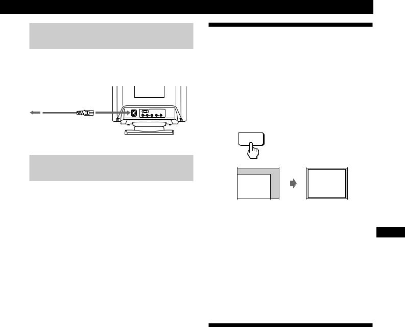
2e étape: Branchez le cordon
d’alimentation
Le moniteur étant hors tension, branchez le cordon d’alimentation au moniteur et l’autre extrémité à une prise murale.
vers une prise |
|
|
|
vers AC IN |
|||
murale |
|||
|
|
||

Cordon d’alimentation (fourni)
Préparation
Réglage automatique de la taille et du centrage de l’image
Une pression sur la touche (ASC) permet de régler automatiquement la taille et le centrage de l’image pour l’adapter à l’écran.
1Mettez le moniteur et l’ordinateur sous tension.
2Appuyez sur la touche ASC.
L’image est ajustée pour s’adapter au centre de l’écran.
ASC
3e étape: Mettez le moniteur et
l’ordinateur sous tension
L’installation de votre moniteur est à présent terminée.
Remarque
Si le message “HORS PLAGE DE BALAYAGE” ou “PAS ENTREE VIDEO” apparaît à l’écran, voir “Messages d’avertissement” à la page 20.
Pour les clients utilisant Windows 95
Installez les informations de nouveau modèle de la “Windows 95 Monitor Information Disk” sur votre PC. (Pour installer le fichier, voir “About the Windows 95 Monitor Information Disk/File”.)
Ce moniteur est conforme à la norme Plug & Play “VESA DDC”. Si votre carte PC/graphique est conforme à DDC, sélectionnez “Plug and Play Monitor (VESA DDC)” comme “Monitor type” dans “Control Panel” sous Windows 95. Certaines cartes PC/graphiques ne sont pas conformes à DDC. Même si votre ordinateur est conforme à DDC, il se peut que vous éprouviez des difficultés à le raccorder à ce moniteur. Dans ce cas, sélectionnez la désignation de modèle de ce moniteur (GDM-400PST ou GDM-500PST) comme “Monitor type” sous Windows 95.
Pour les utilisateurs de Windows NT4.0
L’installation du moniteur sous Windows NT4.0 est différente de celle sous Windows 95 et n’implique pas la sélection du type de moniteur. Reportez-vous au mode d’emploi de Windows NT4.0 pour plus de détails sur le réglage de la résolution, le taux de régénération et le nombre de couleurs.
Remarques
•Cette fonction est prévue pour une utilisation sous Windows ou avec un logiciel à interface graphique similaire qui fournit une
image plein écran. Il se peut qu’elle ne fonctionne pas |
F |
correctement si la couleur d’arrière-plan est sombre ou si l’image |
|
d’entrée ne remplit pas l’écran jusqu’aux bords (telle que l’invite |
|
du MS-DOS). |
|
•Il se peut que l’écran devienne blanc pendant quelques secondes lorsque vous vous exécutez la fonction de réglage automatique de la taille. Il ne s’agit pas d’un dysfonctionnement.
•Bien que les signaux du rapport d’image 5:4 (résolution:
1280 × 1024) ne remplissent pas l’écran jusqu’aux bords, l’image est affichée de manière précise.
Sélection de la langue d’affichage des menus
Pour changer la langue d’affichage des écrans de menu, voir la section “Utilisation de l’écran de menu LANG (langue d’affichage)” à la page 17.
Le réglage par défaut est l’anglais.
7
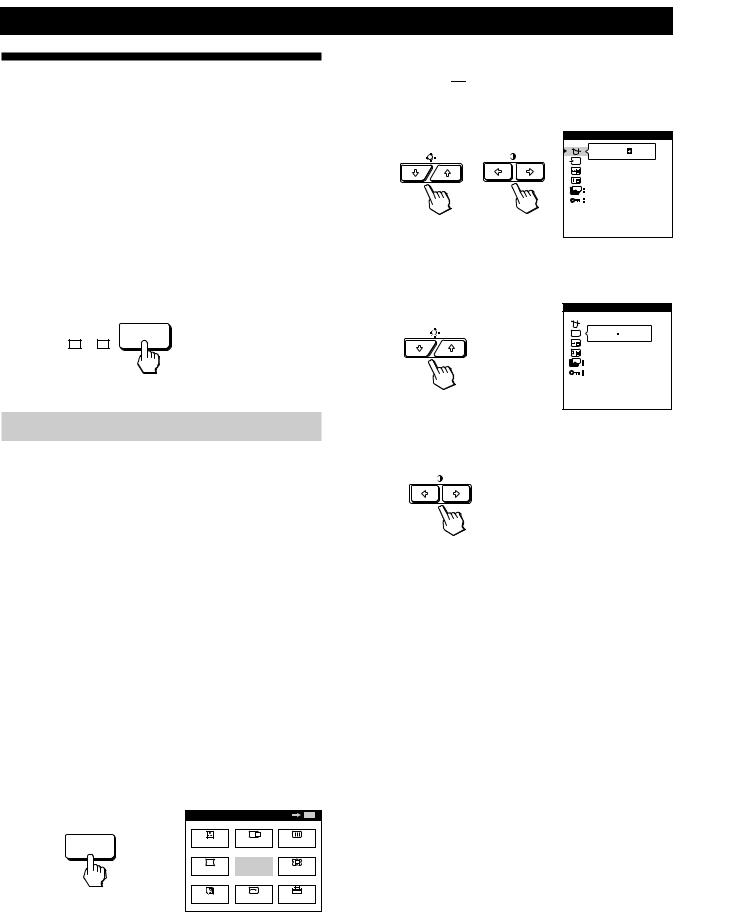
Préparation
Sélection du signal d’entrée
Ce moniteur est doté de deux connecteurs d’entrée de signal (HD15 et 5BNC) et peut être raccordé à deux ordinateurs. Lorsque les deux ordinateurs sont sous tension, sélectionnez le signal que vous voulez visualiser selon la procédure suivante.
1Mettez le moniteur et les deux ordinateurs sous tension.
2Appuyez sur la touche INPUT pour sélectionner le signal d’entrée HD15 ou 5BNC.
Chaque fois que vous appuyez sur la touche INPUT, le signal d’entrée et l’indicateur correspondant alternent.
HD15 BNC INPUT
Sélection du mode de signal d’entrée
Ce moniteur a deux modes de sélection du signal d’entrée, “AUTO” et “MANUEL”.
Si “AUTO” est sélectionné
Si aucun signal n’est entré via le connecteur sélectionné, le moniteur sélectionne automatiquement le signal de l’autre connecteur. Si vous redémarrez l’ordinateur que vous voulez utiliser ou si cet ordinateur se trouve en mode d’économie d’énergie, il se peut que le moniteur sélectionne automatiquement le signal de l’autre connecteur. La raison en est que le moniteur est passé du signal interrompu au signal constant. Si cela se produit, sélectionnez manuellement le signal voulu à l’aide de la touche INPUT.
Si “MANUEL” est sélectionné
Même si aucun signal n’est entré via le connecteur sélectionné, le moniteur ne sélectionne pas le signal de l’autre connecteur.
1Appuyez sur la touche MENU.
L’écran MENU apparaît.
|
MENU |
|
OK |
MENU |
MENU |
COUL. |
CENTRE |
ECRAN |
|
|
|
|
|
|
|
GEOM |
QUITTE |
ZOOM |
|
|
LANG |
TAILLE |
OPTION |
|
2Appuyez sur les touches ¨./>et >?//pour sélectionner “ 


 OPTION” et appuyez à nouveau sur la touche MENU.
L’écran OPTION apparaît.
OPTION |
|
|
OUI |
ZZ... |
1 MIN |
|
|
|
DEVERR |
|
DEGAUSS MANUEL |
3Appuyez sur les touches ¨./>pour sélectionner
“  (ENTREE)”.
OPTION


 AUTO MANUEL
ZZ... |
1 MIN |
|
|
|
DEVERR |
|
ENTREE |
4Appuyez sur les touches >?//pour sélectionner
“AUTO” ou “MANUEL”.
L’écran OPTION disparaît automatiquement au bout d’environ 30 secondes.
Pour désactiver l’écran de menu, appuyez à nouveau sur la touche MENU.
Pour plus de détails sur l’utilisation des écrans de menu, voir “Présentation du système d’écrans de menu” à la page 9.
8
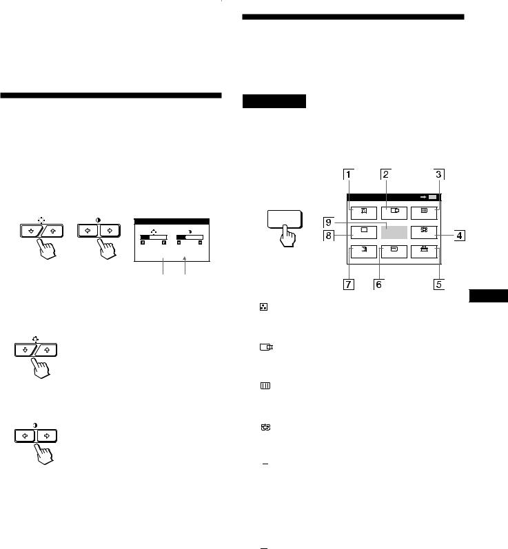
|
|
|
|
Personnalisation de l'affichage |
Personnalisation de l’affichage |
|
|
|
Avant le réglage
•Raccordez le moniteur et l’ordinateur et mettez-les sous tension.
•Sélectionnez “ 
 LANG” dans l’écran MENU et sélectionnez ensuite “FRANÇAIS” (voir page 17).
Présentation du système d’écrans de menu
La plupart des réglages sont effectués à l’aide de l’écran de menu MENU.
Réglage de la luminosité et du contraste de l’image
Ecran MENU
Appuyez sur la touche MENU pour afficher l’écran MENU.
Une fois le réglage effectué, il sera conservé en mémoire |
Cet écran MENU contient des liens avec les autres écrans de |
|
menu décrits ci-dessous. |
||
pour tous les signaux d’entrée reçus. |
||
|
1 Appuyez sur les touches ¨ (luminosité) ./>ou > (contraste) ?//.
L’écran LUMINOSITE/CONTRASTE apparaît. |
|
MENU |
|
OK |
MENU |
|
|
|
|
|
|
||
LUMINOSITE/CONTRASTE |
MENU |
COUL. |
CENTRE |
ECRAN |
||
|
|
|
|
|||
|
|
|
GEOM |
QUITTE |
ZOOM |
|
26 |
26 |
|
|
|
|
|
80.0kHz/ |
75Hz |
|
LANG |
TAILLE |
OPTION |
|
Fréquence |
Fréquence |
|
|
horizontale* |
verticale* |
F |
|
2 Pour le réglage de la luminosité |
|
||
1 |
COUL. |
||
Appuyez sur les touches ¨./>. |
|
Affiche l’écran de menu COULEUR pour le réglage de |
|
|
|
la température des couleurs. |
|
|
2 |
CENTRE |
|
>. . . pour augmenter la luminosité |
Affiche l’écran de menu CENTRAGE pour le réglage du |
||
.. . . pour diminuer la luminosité |
|||
centrage de l’image. |
|||
|
|
||
Pour le réglage du contraste |
3 |
ECRAN |
|
|
Affiche l’écran de menu ECRAN pour le réglage de la |
||
Appuyez sur les touches >?//. |
|
convergence verticale et horizontale, etc. |
|
|
4 |
ZOOM |
|
/. . . pour augmenter le contraste |
Affiche l’écran de menu ZOOM pour agrandir et |
||
?. . . pour diminuer le contraste |
réduire la taille de l’image. |
||
5 


 OPTION
L’écran de menu disparaît automatiquement au bout d’environ 3 secondes.
Pour ramener le réglage à sa valeur par défaut, appuyez sur la touche RESET alors que le menu est affiché. La luminosité est simultanément ramenée à la valeur de réglage par défaut.
*Les fréquences horizontale et verticale pour le signal d’entrée reçu apparaissent dans l’écran de menu LUMINOSITE/ CONTRASTE.
Affiche l’écran de menu OPTION pour ajuster la position de l’écran de menu et démagnétiser l’écran, etc.
6  TAILLE
Affiche l’écran de menu TAILLE pour le réglage de la taille de l’image.
7 
 LANG
LANG
Affiche l’écran de menu LANGUAGE pour sélectionner la langue d’affichage.
8  GEOM
GEOM
Affiche l’écran de menu GEOMETRIE pour régler la rotation et la distorsion en coussin de l’image, etc.
9QUITTE
Referme l’écran MENU.
9
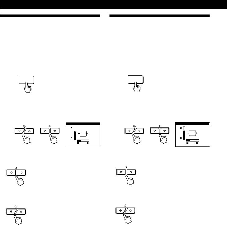
Personnalisation de l’affichage
Utilisation de l’écran de menu CENTRE (centrage)
Les réglages CENTRE vous permettent d’ajuster le centrage de l’image.
Une fois que le réglage est effectué, il sera conservé en mémoire pour le signal d’entrée en cours.
1Appuyez sur la touche MENU.
L’écran MENU apparaît.
MENU
2Appuyez sur les touches ¨./>et >?//pour
sélectionner “
 CENTRE” et appuyez ensuite à nouveau sur la touche MENU.
L’écran de menu CENTRAGE apparaît.
CENTRAGE
73
26
3Pour le réglage horizontal
Appuyez sur les touches >?//.
/. . . pour déplacer l’image vers la droite
?. . . pour déplacer l’image vers la gauche
Pour le réglage vertical
Appuyez sur les touches ¨./>.
>. . . pour déplacer l’image vers le haut
.. . . pour déplacer l’image vers le bas
L’écran de menu disparaît automatiquement au bout d’environ 30 secondes.
Pour refermer l’écran de menu, appuyez à nouveau sur la touche MENU.
Pour réinitialiser les valeurs de réglage, appuyez sur la touche RESET pendant que l’écran est affiché.
Les centrages horizontal et vertical sont tous deux ramenés aux valeurs de réglage par défaut.
Utilisation de l’écran de menu TAILLE
Les réglages TAILLE vous permettent d’ajuster la taille de l’image.
Une fois que le réglage est effectué, il sera conservé en mémoire pour le signal d’entrée en cours.
1Appuyez sur la touche MENU.
L’écran MENU apparaît.
MENU
2Appuyez sur les touches ¨./>et >?//pour
sélectionner “  TAILLE” et appuyez ensuite à nouveau sur la touche MENU.
L’écran de menu TAILLE apparaît.
TAILLE
73
26
3Pour le réglage horizontal
Appuyez sur les touches >?//.
/. . . pour augmenter la taille de
l’image
?. . . pour réduire la taille de l’image
Pour le réglage vertical
Appuyez sur les touches ¨./>.
>. . . pour augmenter la taille de l’image
.. . . pour réduire la taille de l’image
L’écran de menu disparaît automatiquement au bout d’environ 30 secondes.
Pour refermer l’écran de menu, appuyez à nouveau sur la touche MENU.
Pour réinitialiser les valeurs de réglage, appuyez sur la touche RESET pendant que l’écran est affiché.
Les tailles horizontale et verticale sont toutes deux ramenées aux valeurs de réglage par défaut.
10
 Loading...