


A-C4J-100-11 (1)
Color Camera Module
Technical Manual
FCB-EX480C/EX480CP
FCB-EX48C/EX48CP
2005 Sony Corporation
Table of Contents
Features ..................................................................... |
3 |
Precautions ................................................................ |
4 |
Locations of Controls ............................................... |
5 |
Basic Functions ......................................................... |
7 |
Overview of Functions ................................................ |
7 |
Eclipse ...................................................................... |
30 |
Spectral Sensitivity Characteristics .......................... |
30 |
Vibration Specifications ............................................ |
30 |
Key Switch Circuitry ................................................. |
31 |
Key Function Specifications ..................................... |
32 |
Initial Settings, Custom Preset and Backup ............. |
34 |
Mode Condition ........................................................ |
36 |
Command List ......................................................... |
39 |
VISCA/RS-232C Commands ................................... |
39 |
FCB Camera Commands ......................................... |
45 |
Specifications .......................................................... |
59 |
2

Overview
Features
•The EXview HADTM CCD features 380,000 (NTSC) or 440,000 (PAL) effective picture elements and high-sensitivity shooting. The minimum illumination required is 0.7 lux (1/60 s (NTSC), 1/50 s (PAL), ICR OFF).
•18× optical zoom.
•Supports external synchronization (V-lock).
•Adopts a newly developed DSP for improved picture quality when using the digital zoom or the slow shutter.
•An infrared (IR) Cut-Filter can be disengaged from the image path for increased sensitivity in low light environments. The ICR will automatically engage depending on the ambient light, allowing the camera to be effective in day/night environments (FCBEX480C/EX480CP only).
•VISCA is a communications protocol, which enables the camera to be controlled remotely by commands from a host computer/controller.
•Six memory locations are provided to temporarily save and recall up to six sets of camera settings.
•Enhanced Spherical Privacy Zone Masking (max. 24 blocks)
•E-FLIP function
•Alarm function
With consideration given to environmental protection, this module is designed to operate with low power consumption and also incorporates leadfree and halogen-free circuit boards.
3

Overview
Precautions
Software |
Other |
Use of the demonstration software developed by Sony Corporation or use of the software with customer developed application software may damage hardware, the application program or the camera. Sony Corporation is not liable for any damages under these conditions.
Operation
Start the camera control software on your computer after you turn on the camera and the image is displayed.
Operation and Storage Locations
Do not shoot images that are extremely bright (e.g., light sources, the sun, etc.) for long periods of time. Do not use or store the camera in the following extreme conditions:
•Extremely hot or cold places (operating temperature 0 ˚C to +40 ˚C (32 ˚F to 104 ˚F))
•Close to generators of powerful electromagnetic radiation such as radio or TV transmitters
•Where it is subject to fluorescent light reflections
•Where it is subject to unstable (flickering, etc.) lighting conditions
•Where it is subject to strong vibration
Care of the Unit
Remove dust or dirt on the surface of the lens with a blower (commercially available).
Do not apply excessive voltage. (Use only the specified voltage.) Otherwise, you may get an electric shock or a fire may occur.
In case of abnormal operation, contact your authorized Sony dealer or the store where you purchased the product.
4

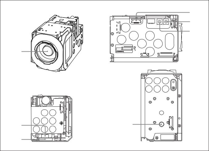
Locations of Controls
FCB-EX480C/EX480CP Main Unit
Front |
Left side |
4
5
6
1
Rear |
Bottom |
|
2 |
7 |
3
1 Lens |
3 CN992 connector |
6 WIDE button |
2 CN991 connector |
4 CN601 connector (for key SW) |
7 Tripod screw holes |
|
5 TELE button |
When a tripod is used, please use |
|
|
10 mm (13/32 in.) screws to attach it |
|
|
to the camera. Also, please be |
|
|
sure to attach the tripod securely. |
5
Locations of Controls
FCB-EX48C/EX48CP Main Unit
Front |
Left side |
4
5
6
1
Rear |
|
Bottom |
|
|
|
2 |
7 |
3
1 Lens |
3 CN992 connector |
6 WIDE button |
2 CN991 connector |
4 CN601 connector (for key SW) |
7 Tripod screw holes |
|
5 TELE button |
When a tripod is used, please use |
|
|
10 mm (13/32 in.) screws to attach it |
|
|
to the camera. Also, please be |
|
|
sure to attach the tripod securely. |
6
Basic Functions
Basic Functions
Overview of Functions
VISCA commands are the basis of camera control.
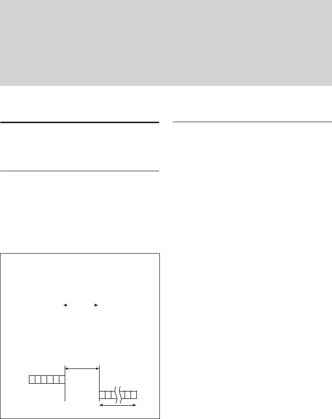
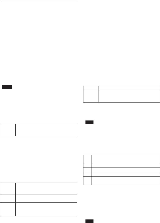
Timing Chart
As VISCA Command processing can only be carried out one time in a Vertical cycle, it takes the maximum 1V cycle time for an ACK/Completion to be returned. If the Command ACK/Completion communication time can be cut shorter than the1V cycle time, then every 1V cycle can receive a Command.
General Commands
|
Command |
|
|
|
|
|
|
|
|
|
|
|
|||||
RxD |
|
|
|
|
|
|
|
|
|
|
ACK Completion |
||||||
|
|
|
|
|
|
|
|
|
|
||||||||
|
|
|
|
|
|
|
|
|
|
||||||||
|
|
|
|
|
|
|
|
|
|
|
|||||||
TxD |
|
|
|
|
|
|
|
|
|
|
|
|
|
|
|
|
|
|
|
|
|
|
|
|
|
|
|
|
|
|
|
|
|
|
|
|
|
Within 16.7msec(20msec*PAL) |
|||||||||||||||
Query Commands
|
Within 16.7msec(20msec*PAL) |
|
Command |
RxD |
Completion |
TxD |
|
|
16 Byte |
Commands
•Power On/Off
Powers the camera on and off. When the power is off, the camera is able to accept only the lowest level of VISCA Commands; the display and other features are turned off.
•I/F clear
Clears the Command buffer of the FCB camera. Clearing the buffer can also be carried out from the control application software when the power is on.
•Address set
VISCA is a protocol, which normally can support a daisy chain of up to seven attached devices. However, the FCB camera does not support camera connections in a daisy chain. Therefore, whenever a camera is connected for the first time, be sure to use the address set to confirm the address.
•ID Write
Sets the camera ID.
•Mute
Blanks the screen and sends out a synchronizing signal.
•Lens Initialization
Initializes the zoom and focus of the lens. Even when power is already on, it initializes the zoom and the focus.
•Comp Scan
A pixel blemish-masking feature is used to reevaluate overall CCD pixel blemishes and mask severely flawed pixels automatically upon receiving the COMP SCAN command. This feature helps to mask the flaws found in CCD imagers, even after the camera has been powered on for some time.
7

Zoom
The FCB camera employs an 18× optical zoom lens combined with a digital zoom function allowing you to zoom up to 216×.
Lens specifications: Optical 18×, f = 4.1 to 73.8 mm (F1.4 to F3.0)
The horizontal angle of view is approximately 48 degrees (wide end) to 2.8 degrees (tele end). Digital Zoom enlarges the center of the subject by expanding each image in both the vertical and horizontal directions. When 216× zoom is used, the
number of effective picture elements in each direction reduces to 1/12 and the overall resolution deteriorates.
You can activate the zoom in the following two ways:
•By pressing the TELE or WIDE buttons on the camera itself.
•Using a VISCA Command
Using Standard Mode
Using Variable Mode
There are eight levels of zoom speed.
Direct Mode
Setting the zoom position enables quick movement to the designated position.
Digital Zoom ON/OFF
In these standard and variable Speed Modes, it is necessary to send a “Stop Command” to stop the zoom operation.
•The Zoom Mode supports a Combined Mode and a Separate Mode.
Combined Mode
This is the previously existing zoom method. After the optical zoom has reached its maximum level, the camera switches to Digital Zoom Mode.
Separate Mode
In this mode, Optical Zoom and Digital Zoom can be operated separately. You can use digital zoom magnification at any time from within any level of optical magnification.
Focus
Focus has the following modes, all of which can be set using VISCA Commands.
•Auto Focus Mode
The minimum focus distance is 290 mm at the optical wide end and 800 mm at the optical tele end (distance from the front end of the lens), and is independent of the digital zoom.
Basic Functions
The AutoFocus (AF) function automatically adjusts the focus position to maximize the high frequency content of the picture in a center measurement area, taking into consideration the high luminance and strong contrast components.
- Normal AF Mode
This is the normal mode for AF operations.
- Interval AF Mode
The mode used for AF movements carried out at defined intervals. The time intervals for AF movements and for the timing of the stops can be set in one-second increments using the Set Time Command. The initial value for both is set to five seconds.
- Zoom Trigger Mode
When the zoom is changed with the TELE or the WIDE buttons, the pre-set value (initially set at 5 seconds) becomes that for AF Mode. Then, it returns to Manual Focus mode.
AF sensitivity can be set to either Normal or LOW.
- Normal
Reaches the highest focus speed quickly. Use this when shooting a subject that moves frequently. Usually, this is the most appropriate mode.
- LOW
Improves the stability of the focus. When the lighting level is low, the AF function does not take effect, even though the brightness varies, contributing to a stable image.
•Manual Focus Mode
Manual Focus has both a Standard Speed Mode and a Variable Speed Mode. Standard Speed Mode focuses at a fixed rate of speed. Variable Speed Mode has eight speed levels that can be set using a VISCA Command.
In these standard and variable Speed Modes, it is necessary to send a “Stop Command” to stop the zoom operation.
•One Push Trigger Mode
When a Trigger Command is received, the lens moves to adjust the focus for the subject. The focus lens then holds the same position until the next Trigger Command is input.
•Infinity Mode
The lens is forcibly moved to a position suitable for an unlimited distance.
•Near Limit Mode
Can be set in a range from 1000 (∞) to C000 (10 mm). The focus range is narrowed by excluding the unnecessary range.
8

White Balance
White Balance has the following modes, all of which can be set using VISCA Commands.
•Auto White Balance
This mode computes the white balance value output using color information from the entire screen. It outputs the proper value using the color temperature radiating from a black subject based on a range of values from 3000 to 7500K.
This mode is the default setting.
•ATW
Auto Tracing White balance (2000 to 10000 K)
•Indoor
3200 K Base Mode
•Outdoor
5800 K Base Mode
•One Push WB
The One Push White Balance mode is a fixed white balance mode that may be automatically readjusted only at the request of the user (One Push Trigger), assuming that a white subject, in correct lighting conditions and occupying more than 1/2 of the image, is submitted to the camera.
One Push White Balance data is lost when the power is turned off. If the power is turned off, reset the One Push White Balance.
•Manual WB
Manual control of R and B gain, 256 steps each
Automatic Exposure Mode
The variety of AE functions, which allow video signal to output the optimum image for subjects from low light conditions to bright light conditions, are available.
•Full Auto
Auto Iris and Gain, Fixed Shutter Speed (NTSC: 1/60 s, PAL: 1/50 s)
•Shutter Priority 1)
Variable Shutter Speed, Auto Iris and Gain
(1/1 to 1/10,000 s, 22 steps, std. shutter: 16 steps, slow shutter: 6 steps)
•Iris Priority
Variable Iris (F1.4 to Close, 18 steps), Auto Gain and Shutter speed.
•Manual
Variable Shutter, Iris and Gain.
•Bright
Variable Iris and Gain (Close to F1.6, 17 steps at 0 dB: F1.4, 15 steps from 0 to 28 dB)
Basic Functions
AE – Shutter Priority
The shutter speed can be set freely by the user to a total of 22 steps – 16 high speeds and 6 low speeds. When the slow shutter is set, the speed can be 1/30, 1/15, 1/8, or 1/4 s. The picture output is read at a normal
rate from the memory. The memory is updated at a low rate from the CCD. AF capability is low.
In high speed mode, the shutter speed can be set up to 1/10,000 s. The iris and gain are set automatically, according to the brightness of the subject.
Data |
NTSC |
PAL |
|
|
|
15 |
10000 |
10000 |
|
|
|
14 |
6000 |
6000 |
|
|
|
13 |
4000 |
3500 |
|
|
|
12 |
3000 |
2500 |
|
|
|
11 |
2000 |
1750 |
|
|
|
10 |
1500 |
1250 |
|
|
|
0F |
1000 |
1000 |
|
|
|
0E |
725 |
600 |
|
|
|
0D |
500 |
425 |
|
|
|
0C |
350 |
300 |
|
|
|
0B |
250 |
215 |
|
|
|
0A |
180 |
150 |
|
|
|
09 |
125 |
120 |
|
|
|
08 |
100 |
100 |
|
|
|
07 |
90 |
75 |
|
|
|
06 |
60 |
50 |
|
|
|
05 |
30 |
25 |
|
|
|
04 |
15 |
12 |
|
|
|
03 |
8 |
6 |
|
|
|
02 |
4 |
3 |
|
|
|
01 a) |
2 |
2 |
00 a) |
1 |
1 |
a) For AE-Manual only.
Note
When the shutter speed 1/1 s or 1/2 s is used, Auto Focus and White Balance may not function fully.
AE – Iris Priority
The iris can be set freely by the user to 18 steps between F1.4 and Close.
The gain and shutter speed are set automatically according to the brightness of the subject.
Data |
Setting value |
Data |
Setting value |
|
|
|
|
11 |
F1.4 |
08 |
F6.8 |
|
|
|
|
10 |
F1.6 |
07 |
F8.0 |
|
|
|
|
0F |
F2.0 |
06 |
F9.6 |
|
|
|
|
0E |
F2.4 |
05 |
F11 |
|
|
|
|
0D |
F2.8 |
04 |
F14 |
|
|
|
|
0C |
F3.4 |
03 |
F16 |
|
|
|
|
0B |
F4.0 |
02 |
F19 |
|
|
|
|
0A |
F4.8 |
01 |
F22 |
|
|
|
|
09 |
F5.6 |
00 |
CLOSE |
.................................................................................................................................................................................................................................
1) Flicker can be eliminated by setting shutter to: |
t1/120 s for PAL models used in countries with a 60 Hz power supply |
t1/100 s for NTSC models used in countries with a 50 Hz power supply |
frequency. |
frequency. |
|
9
AE – Manual
The shutter speed (22 steps), iris (18 steps) and gain (16 steps) can be set freely by the user.
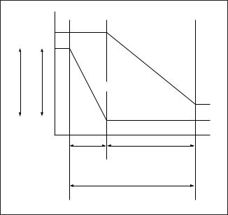
AE – Bright
The bright control function adjusts both the gain and iris using an internal algorithm according to a brightness level freely set by the user. Exposure is controlled by gain when dark and by iris when bright. As both gain and iris are fixed, this mode is used when exposing at a fixed camera sensitivity. When switching from Full Auto or Shutter Priority Mode to Bright Mode, the current status will be retained for a short period of time.
Only when the AE mode is set to “Full Auto” or “Shutter Priority,” the user can switch it to “Bright.”
Gain |
|
IRIS AGC |
|
OPEN MAX |
|
|
IRIS curve |
|
Gain curve |
CLOSE MIN |
|
Dark |
Bright |
Controlled |
Controlled by IRIS |
by gain |
|
Bright limit which controllable for this unit
Data |
Iris |
Gain |
Data |
Iris |
Gain |
1F |
F1.4 |
28 dB |
0F |
F2.0 |
0 dB |
|
|
|
|
|
|
1E |
F1.4 |
26 dB |
0E |
F2.4 |
0 dB |
|
|
|
|
|
|
1D |
F1.4 |
24 dB |
0D |
F2.8 |
0 dB |
|
|
|
|
|
|
1C |
F1.4 |
22 dB |
0C |
F3.4 |
0 dB |
|
|
|
|
|
|
1B |
F1.4 |
20 dB |
0B |
F4.0 |
0 dB |
|
|
|
|
|
|
1A |
F1.4 |
18 dB |
0A |
F4.8 |
0 dB |
|
|
|
|
|
|
19 |
F1.4 |
16 dB |
09 |
F5.6 |
0 dB |
|
|
|
|
|
|
18 |
F1.4 |
14 dB |
08 |
F6.8 |
0 dB |
|
|
|
|
|
|
17 |
F1.4 |
12 dB |
07 |
F8.0 |
0 dB |
|
|
|
|
|
|
16 |
F1.4 |
10 dB |
06 |
F9.6 |
0 dB |
|
|
|
|
|
|
15 |
F1.4 |
8 dB |
05 |
F11 |
0 dB |
|
|
|
|
|
|
14 |
F1.4 |
6 dB |
04 |
F14 |
0 dB |
|
|
|
|
|
|
13 |
F1.4 |
4 dB |
03 |
F16 |
0 dB |
|
|
|
|
|
|
12 |
F1.4 |
2 dB |
02 |
F19 |
0 dB |
|
|
|
|
|
|
11 |
F1.4 |
0 dB |
01 |
F22 |
0 dB |
|
|
|
|
|
|
10 |
F1.6 |
0 dB |
00 |
CLOSE |
0 dB |
|
|
|
|
|
|
Basic Functions
When switching from the Shutter Priority mode to the Bright mode, the shutter speed set in the Shutter Priority mode is maintained.
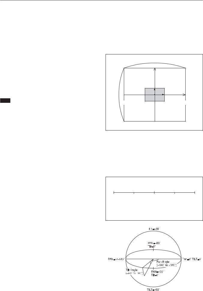
Spot Exposure Mode
In Full Auto AE, the level for the entire screen is computed and the optimum Auto Iris and Gain levels are determined. In Spot AE, a particular section of the subject can be designated, and then that portion of the image can be weighted and a value computed so that Iris and Gain can be optimized to obtain an image. For example, in an image with a lot of movement and with varying levels of brightness, portions without much change can be designated as such a “spot,” and changes to the screen can be minimized in that area. As shown in the diagram below, a range of 16 blocks vertically and 16 blocks horizontally can be designated.
In the case where the center is designated (shown in black), the level is computed along with a weighted value for the surrounding block (shaded), including the specified portions; and then the Gain and Iris are set. The value of the designated portions and the surrounding areas should be calculated as 90% and the rest should be set to 10%. The range of the Spot AE frame is fixed to five blocks vertically and four blocks horizontally.
|
|
|
|
|
|
Horizontal 16 |
|||||||||||
|
0 1 2 3 4 5 6 7 8 9 A B C D E F |
||||||||||||||||
0 |
|
|
|
|
|
|
|
|
|
|
|
|
|
|
|
|
|
1 |
|
|
|
|
|
|
|
|
|
|
|
|
|
|
|
|
|
2 |
|
|
|
|
|
|
|
|
|
|
|
|
|
|
|
|
|
Vertical 16 43 |
|
|
|
|
|
|
|
|
|
|
|
|
|
|
|
|
|
|
|
|
|
|
|
|
|
|
|
|
|
|
|
|
|
|
|
5 |
|
|
|
|
|
|
|
|
|
|
|
|
|
|
|
|
|
6 |
|
|
|
|
|
|
|
|
|
|
|
|
|
|
|
|
|
7 |
|
|
|
|
|
|
|
|
|
|
|
|
|
|
|
|
|
8 |
|
|
|
|
|
|
|
|
|
|
|
|
|
|
|
|
|
9 |
|
|
|
|
|
|
|
|
|
|
|
|
|
|
|
|
|
A |
|
|
|
|
|
|
|
|
|
|
(8,8) |
|
|
|
|
|
|
B |
|
|
|
|
|
|
|
|
|
|
|
|
|
|
|
|
|
C |
|
|
|
|
|
|
|
|
|
|
|
|
|
|
|
|
|
D |
|
|
|
|
|
|
|
|
|
|
|
|
|
|
|
|
|
E |
|
|
|
|
|
|
|
|
|
|
|
|
|
|
|
|
|
F |
|
|
|
|
|
|
|
|
|
|
|
|
|
|
|
|
|
|
|
|
|
|
|
|
|
|
|
|
|
|
|
|
|
|
|
10
Exposure Compensation
Exposure compensation is a function which offsets the internal reference brightness level used in the AE mode by steps of 1.5 dB.
Data |
Step |
Setting value |
|
|
|
0E |
7 |
10.5 dB |
|
|
|
0D |
6 |
9 dB |
|
|
|
0C |
5 |
7.5 dB |
|
|
|
0B |
4 |
6 dB |
|
|
|
0A |
3 |
4.5 dB |
|
|
|
09 |
2 |
3 dB |
|
|
|
08 |
1 |
1.5 dB |
|
|
|
07 |
0 |
0 dB |
|
|
|
06 |
–1 |
–1.5 dB |
|
|
|
05 |
–2 |
–3 dB |
|
|
|
04 |
–3 |
–4.5 dB |
|
|
|
03 |
–4 |
–6 dB |
|
|
|
02 |
–5 |
–7.5 dB |
|
|
|
01 |
–6 |
–9 dB |
|
|
|
00 |
–7 |
–10.5 dB |
|
|
|
Aperture Control
Aperture control is a function which adjusts the enhancement of the edges of objects in the picture. There are 16 levels of adjustment, starting from “no enhancement.” When shooting text, this control may help by making the text sharper.
Back Light Compensation
When the background of the subject is too bright, or when the subject is too dark due to shooting in the AE mode, back light compensation will make the subject appear clearer.
Slow Shutter – Auto/Manual
When the Slow Shutter is set to “Auto,” this ensures that the slow shutter is engaged automatically when the brightness drops. This occurs only when the AE mode is set to “Full Auto.”
“Slow Shutter Manual” is the factory setting.
ICR (IR Cut-Removable) Mode (FCB-EX480C/EX480CP only)
An infrared (IR) Cut-Filter can be disengaged from the image path for increased sensitivity in low light environments. The ICR will automatically engage depending on the ambient light, allowing the camera to be effective in day/night environments. (FCBEX480C/EX480CP only)
Basic Functions
Auto ICR Mode (FCB-EX480C/EX480CP only)
Auto ICR Mode automatically switches the settings needed for attaching or removing the IR Cut Filter. With a set level of darkness, the IR Cut Filter is automatically disabled (ICR ON), and the infrared sensitivity is increased. With a set level of brightness, the IR Cut Filter is automatically enabled (ICR OFF). Also on systems equipped with an IR light, the internal data of the camera is used to make the proper decisions to avoid malfunctions.
When Auto Slow Shutter is OFF (PRESLOW mode ON (default) or OFF)
ICR |
|
IRIS |
|
ON |
|
|
|
AGC |
OPEN |
|
|
|
|
||
|
|
|
|
(Iris Open) |
MAX |
|
|
|
|
|
|
(Gain Max) |
|
|
|
ICR ON |
|
|
IRIS |
|
GAIN |
|
|
|
|
|
(Iris Min) |
|
|
|
(0dB) |
|
Adjustable |
|
(1/60 sec) |
|
|
SHUTTER |
|
Dark |
|
|
Bright |
|
ICR ON t OFF Adjustable |
|
|
When Auto Slow Shutter is ON (PRESLOW mode OFF)
ICR |
|
IRIS |
|
AGC |
OPEN |
|
|
ON |
|
||
(Iris Open) |
MAX |
|
|
|
|
|
|
(Gain Max) |
|
|
|
ICR ON |
|
|
IRIS |
(Slow Shutter Max) |
GAIN |
|
|
|
|
|
|
|
|
|
(Iris Min) |
|
|
|
(0dB) |
|
Adjustable |
|
(1/60 sec) |
|
|
SHUTTER |
|
Dark |
|
|
Bright |
ICR ON t OFF Adjustable |
|
||
When Auto Slow Shutter is ON (PRESLOW mode ON (default))
ICR |
|
IRIS |
ON |
AGC |
OPEN |
|
|
|
(Iris Open) |
MAX |
|
|
|
|
(Gain Max) |
|
|
ICR ON |
|
IRIS |
(Slow Shutter Max) |
GAIN |
|
|
|
|
|
|
(Iris Min) |
|
|
(0dB) |
|
Adjustable |
(1/60 sec) |
|
SHUTTER |
|
Dark |
|
Bright |
|
ICR ON t OFF Adjustable |
|
|
|
11 |

Note
When in Auto_ICR_OFF state and WB data is added (default), a malfunction may occur when the subjects largely consisting of blue and red colors are taken. Auto ICR is available in AE-full-auto state only.
Camera ID
The ID can be set up to 65,536 (0000 to FFFF). As this will be memorized in the nonvolatile memory inside the camera, data will be saved regardless of whether it has been backed up.
Effect
It consists of the following functions.
•Neg. Art: Negative/Positive Reversal
•Black White: Monochrome Image
Others
E-FLIP
This function turns the video output from the camera upside down.
Mirror Image
This function reverses the video output from the camera horizontally.
Freeze
This function captures an image in the field memory of the camera so that this image can be output continuously.
Because communication inside the camera is based on V cycle, the captured image is always the one 3V to 4Vs after the sending of a Command. Thus, you can not specify a time period after sending EVEN, ODD or a Command.
Memory (Position Preset)
Using the position preset function, 6 sets of camera shooting conditions can be stored and recalled.
This function allows you to achieve the desired status instantly even without adjusting the following items each time:
•Zoom Position
•Digital Zoom On/Off
•Focus Auto/Manual
•Focus Position
•AE Mode
•Shutter control parameters
•Bright Control
•Iris control parameters
•Gain control parameters
•Exposure Compensation On/Off
•Exposure Level
Basic Functions
•Backlight Compensation On/Off
•Slow Shutter Auto/Manual
•White Balance Mode
•R/B Gain
•Aperture
•ICR Shoot On/Off
Custom Preset
As with the position preset function, the camera shooting conditions can be stored and recalled. The settings are recalled when the power is turned on.
For setting items, see the “Initial Settings, Custom Preset and Backup” section on page 34.
User Memory Area
A user area of 16 bytes allows you to write data, such as an ID for each customer, data for each system, and so on, freely.
Note
Rewriting of memory is not unlimited. Be careful to avoid using the memory area for such as unnecessary tasks as rewriting the contents of the memory for every operation.
Privacy Zone Settings
For details, see page 14.
Alarm
For details, see page 18.
12

|
|
|
|
|
|
|
|
|
|
Basic Functions |
|
|
|
|
|
|
|
|
|
|
|
Title Display |
|
|
|
|
|
|
|
|
Synchronization Methods |
|
The camera can be given a title containing up to 20 |
|
Internal and external synchronization are available; |
||||||||
characters such as “ENTRANCE” or “LOBBY”. The |
|
VISCA Commands allow you to switch between them. |
||||||||
position of the first character (horizontal, vertical) of |
|
• Internal Synchronization |
||||||||
the title, blinking state, and color can also be changed. |
|
|||||||||
|
An internal vibrator inside the camera generates a |
|||||||||
|
|
|
|
|
|
|
|
|
|
|
|
|
|
|
|
|
|
|
|
|
synchronizing signal as a basic oscillator. |
Vposition |
|
|
|
00 to 0A |
|
|
||||
|
|
|
|
|
|
NTSC=28.636363MHz |
||||
|
|
|
|
|
|
|
|
|
|
|
Hposition |
|
|
|
00 to 17 |
|
|
||||
|
|
|
|
|
|
PAL=28.375MHz |
||||
|
|
|
|
|
|
|
|
|
|
|
Blink |
|
|
|
00: Does not blink |
|
|||||
|
|
|
|
|
• External Synchronization (V-Lock Synchronization) |
|||||
|
|
|
|
|
|
|
|
|
||
|
|
|
|
01: Blinks |
|
|
||||
|
|
|
|
|
|
|
|
When a TTL level V-Lock pulse is input, the camera |
||
|
|
|
|
|
|
|
|
|
|
|
|
|
|
|
00 |
|
|
White |
|
||
|
|
|
|
|
|
|
|
synchronizes to the input signal (V-lock |
||
|
|
|
|
|
|
|
|
|
|
|
|
|
|
|
01 |
|
|
Yellow |
|
||
|
|
|
|
|
|
|
|
synchronization). The frequency of the input signal |
||
|
|
|
|
|
|
|
|
|
|
|
|
|
|
|
02 |
|
|
Violet |
|
||
|
|
|
|
|
|
|
|
synchronizes to within ±1Hz of the external |
||
|
|
|
|
|
|
|
|
|
|
|
Color |
|
|
|
03 |
|
|
Red |
|
||
|
|
|
|
|
|
|
synchronization. |
|||
|
|
|
|
04 |
|
|
Cyan |
|
|
Also, V-Phase phase adjustment can be carried out to |
|
|
|
|
05 |
|
|
Green |
|
|
within ±90 degrees due to the V-Lock phase |
|
|
|
|
06 |
|
|
Blue |
|
|
adjustment. In addition, 360 degree phase adjustment |
|
|
|
|
|
|
|
|
|
|
is possible because you can switch between 0 degree |
|
|
|
|
|
|
|
|
|
||
|
|
|
|
|
|
|
|
|
|
and 180 degree phases. |
00 |
01 |
02 |
03 |
04 |
05 |
|
06 |
07 |
|
Because V-Lock synchronization is a simple synchronization |
A |
B |
C |
D |
E |
F |
G |
H |
|
method, color signals like a VBS “GenLock” cannot be |
|
|
|
|
|
|
|
|
|
|
|
synchronized. |
08 |
09 |
0a |
0b |
0c |
0d |
0e |
0f |
|
||
|
|
|||||||||
|
|
|
|
|
|
|
|
|
|
|
I |
J |
K |
L |
M |
N |
O |
P |
|
|
|
|
|
|
|
|
|
|
|
|
|
|
10 |
11 |
12 |
13 |
14 |
15 |
|
16 |
17 |
|
|
|
|
|
|
|
|
|
|
|
|
|
Q |
R |
S |
T |
U |
V |
W |
X |
|
|
|
|
|
|
|
|
|
|
|
|
|
|
18 |
19 |
1a |
1b |
1c |
1d |
1e |
1f |
|
|
|
|
|
|
|
|
|
|
|
|
|
|
Y |
Z |
& |
|
? |
! |
|
1 |
2 |
|
|
|
|
|
|
|
|
|
|
|
|
|
20 |
21 |
22 |
23 |
24 |
25 |
|
26 |
27 |
|
|
|
|
|
|
|
|
|
|
|
|
|
3 |
4 |
5 |
6 |
7 |
8 |
|
9 |
0 |
|
|
|
|
|
|
|
|
|
|
|
|
|
28 |
29 |
2a |
2b |
2c |
2d |
2e |
2f |
|
|
|
|
|
|
|
|
|
|
|
|
|
|
À |
È |
Ì |
Ò |
Ù |
Á |
|
É |
Í |
|
|
|
|
|
|
|
|
|
|
|
|
|
30 |
31 |
32 |
33 |
34 |
35 |
|
36 |
37 |
|
|
|
|
|
|
|
|
|
|
|
|
|
Ó |
Ú |
 |
Ê |
Ô |
Æ |
|
Π|
à |
|
|
|
|
|
|
|
|
|
|
|
|
|
38 |
39 |
3a |
3b |
3c |
3d |
3e |
3f |
|
|
|
|
|
|
|
|
|
|
|
|
|
|
Õ |
Ñ |
Ç |
ß |
Ä |
Ï |
|
Ö |
Ü |
|
|
|
|
|
|
|
|
|
|
|
|
|
40 |
41 |
42 |
43 |
44 |
45 |
|
46 |
47 |
|
|
|
|
|
|
|
|
|
|
|
|
|
Å |
$ |
F |
¥ |
DM |
£ |
|
¿ |
¡ |
|
|
|
|
|
|
|
|
|
|
|
|
|
48 |
49 |
4a |
4b |
4c |
4d |
4e |
4f |
|
|
|
|
|
|
|
|
|
|
|
|
|
|
ø |
“ |
: |
‘ |
. |
, |
|
/ |
- |
|
|
|
|
|
|
|
|
|
|
|
|
|
13

Privacy Zone Function
Privacy Zone masking protects private objects and areas such as house windows, entrances, and exits which are within the camera’s range of vision but not subject to surveillance.
Privacy zone masking can be masked on the monitor to protect privacy.
Basic Functions
Features
•Mask can be set on up to 24 places according to Pan/ Tilt positions.
•Mask can be displayed on 8 places per screen simultaneously.
•Privacy Zones are displayed according to priority in alphabetical order.
•Individual on/off zone masking settings.
•Two colors from among 28 colors can be individually set for each of 24 privacy zones.
•Interlocking control with zooming.
•Interlocking control with Pan/Tilt.
•Non-interlocking control with Pan/Tilt.
Timing chart |
|
8x 01 |
.. .. FF |
(Mask Setting Command) |
|
|
1V |
|
Setting command is reflected |
|
at this timing. |
14
|
|
|
|
Basic Functions |
|
|
|
|
|
Privacy Zone Setting Command List |
|
|||
|
|
|
|
|
Command Set |
Command |
|
Command Packet |
Comments |
|
|
|
|
|
CAM_PrivacyZone |
SetMask |
|
8x 01 04 76 mm nn |
Setting Mask(Size) |
|
|
|
0r 0r 0s 0s FF |
See “mm: mask setting list”, “nn: setting”, and |
|
|
|
|
“rr: w, ss: h” in “Parameters” on page 16. |
|
|
|
|
|
|
Display |
|
8x 01 04 77 pp pp pp pp FF |
Setting Mask Display On/Off |
|
|
|
|
See “pp pp pp pp: Mask bit” in “Parameters” |
|
|
|
|
on page 16. |
|
|
|
|
pp pp pp pp: Mask setting (0: OFF, 1: ON) |
|
|
|
|
|
|
SetMaskColor |
|
8x 01 04 78 pp pp pp pp qq rr FF |
Setting Color of Mask |
|
|
|
|
See “pp pp pp pp: Mask bit” and “qq, rr: Color |
|
|
|
|
code” in “Parameters” on page 16. |
|
|
|
|
qq: Color setting when setting the Mask bit |
|
|
|
|
to 0 |
|
|
|
|
rr: Color setting when setting the Mask bit |
|
|
|
|
to 1 |
|
|
|
|
|
|
SetPanTiltAngle |
|
8x 01 04 79 0p 0p 0p 0q 0q 0q FF |
Setting Pan/Tilt Angle |
|
|
|
|
See “Setting pan/tilt angle” in “Parameters” on |
|
|
|
|
page 16. |
|
|
|
|
ppp: Pan angle, qqq: Tilt angle |
|
|
|
|
|
|
SetPTZMask |
|
8x 01 04 7B mm 0p 0p 0p |
Setting the direct position of PTZ |
|
|
|
0q 0q 0q 0r 0r 0r 0r FF |
mm: See “mm: mask setting list” and “Setting |
|
|
|
|
pan/tilt angle” in “Parameters” on page 16. |
|
|
|
|
ppp: Pan , qqq: Tilt , rrrr: Zoom |
|
|
|
|
|
|
Non_InterlockMask |
|
8x 01 04 6F mm |
Setting non-interlocking the mask to pan/tilt |
|
|
|
0p 0p 0q 0q 0r 0r 0s 0s FF |
See “mm: mask setting list” and “pp: x, qq: y, |
|
|
|
|
rr: w, ss: h” in “Parameters” on page 16. |
|
|
|
|
|
|
Grid On |
|
8x 01 04 7C 02 FF |
Setting Grid Display On/Off |
|
|
|
|
|
|
Grid Off |
|
8x 01 04 7C 03 FF |
|
|
|
|
|
|
|
CenterLineOn |
|
8x 01 04 7C 04 FF |
Setting the center line On |
|
|
|
|
|
|
|
|||
Privacy Zone Inquiry Command List |
|
|||
|
|
|
|
|
Inquiry Command |
Command Packet |
|
Inquiry Packet |
Comments |
|
|
|
|
|
CAM_Privacy |
8x 09 04 77 FF |
|
y0 50 pp pp pp pp FF |
Inquiry about the status of Setting Mask |
DisplayInq |
|
|
|
Display On/Off |
|
|
|
|
See “pp pp pp pp: Mask bit” in “Parameters” |
|
|
|
|
on page 16. |
|
|
|
|
1:On, 0:Off |
|
|
|
|
|
CAM_PrivacyPan |
8x 09 04 79 FF |
|
y0 50 0p 0p 0p 0q 0q 0q FF |
Inquiry about the pan/tilt position currently set |
TiltInq |
|
|
|
See “Setting pan/tilt angle” in “Parameters” on |
|
|
|
|
page 16. |
|
|
|
|
ppp: Pan, qqq: Tilt |
|
|
|
|
|
CAM_Privacy |
8x 09 04 7B mm FF |
|
y0 50 0p 0p 0p 0q 0q 0q 0r 0r |
Inquiry about pan/tilt/zoom position at the mm |
PTZInq |
|
|
0r 0r FF |
Mask setting |
|
|
|
|
See “mm: Mask setting list” and “Setting pan/ |
|
|
|
|
tilt angle” in “Parameters” on page 16. |
|
|
|
|
ppp: Pan Position, |
|
|
|
|
qqq: Tilt Position |
|
|
|
|
rrrr: Zoom Position |
|
|
|
|
|
CAM_Privacy |
8x 09 04 6F FF |
|
y0 50 pp pp pp pp FF |
Inquiry about the mask currently displayed |
MonitorInq |
|
|
|
See “pp pp pp pp: Mask bit” in “Parameters” |
|
|
|
|
on page 16. |
|
|
|
|
|
15
Basic Functions
Parameters
mm: Mask setting list
Mask Name |
mm (Hex) |
|
|
Mask_A |
00h |
|
|
Mask_B |
01h |
|
|
Mask_C |
02h |
|
|
Mask_D |
03h |
|
|
Mask_E |
04h |
|
|
Mask_F |
05h |
|
|
Mask_G |
06h |
|
|
Mask_H |
07h |
|
|
Mask_I |
08h |
|
|
Mask_J |
09h |
|
|
Mask_K |
0Ah |
|
|
Mask_L |
0Bh |
|
|
Note
Mask Name |
mm (Hex) |
Mask_M |
0Ch |
|
|
Mask_N |
0Dh |
|
|
Mask_O |
0Eh |
|
|
Mask_P |
0Fh |
|
|
Mask_Q |
10h |
|
|
Mask_R |
11h |
|
|
Mask_S |
12h |
|
|
Mask_T |
13h |
|
|
Mask_U |
14h |
|
|
Mask_V |
15h |
|
|
Mask_W |
16h |
|
|
Mask_X |
17h |
|
|
The priority order of the mask display is in the sequence from A (highest) to X (lowest).
When you set the parameters of masks non-sequentially, it is recommended that you set the mask whose priority order is higher, first.
nn: Setting
nn |
Setting |
|
|
00 |
Resetting the zone size (the value of w, h) |
|
for the existing mask. |
|
|
01 |
Setting newly the zone size (the value of |
|
w, h). |
|
|
pp: x, qq: y, rr: w, ss: h
160 |
|
3Ch |
|
|
mask |
h |
w |
120 |
(x,y) |
0 |
|
B0h |
50h |
C4h
Effective display area
pp pp pp pp: Mask bit
|
pp |
|
|
|
|
|
|
|
pp |
|
|
|
|
|
|
|
pp |
|
|
|
|
|
|
|
pp |
|
|
|
|
|
|
|
||||
bit |
7 |
|
6 |
5 |
4 |
3 |
2 |
1 |
0 |
7 |
|
6 |
5 |
4 |
3 |
2 |
1 |
0 |
7 |
|
6 |
5 |
4 |
3 |
2 |
1 |
0 |
7 |
|
6 |
5 |
4 |
3 |
2 |
1 |
0 |
|
|
|
|
|
|
|
|
|
|
|
|
|
|
|
|
|
|
|
|
|
|
|
|
|
|
|
|
|
|
|
|
|
|
|
|
|
Mask |
- |
|
- |
X |
W |
V |
U |
T |
S |
- |
|
- |
R |
Q |
P |
O |
N |
M |
- |
|
- |
L |
K |
J |
I |
H |
G |
- |
|
- |
F |
E |
D |
C |
B |
A |
|
|
|
|
|
|
|
|
|
|
|
|
|
|
|
|
|
|
|
|
|
|
|
|
|
|
|
|
|
|
|
|
|
|
|
|
|
qq, rr: Color code
Mask (Color) |
Code (qq, rr) |
Semi-transparency (qq, rr) |
|
|
|
Black |
00h |
10h |
Gray1 |
01h |
11h |
Gray2 |
02h |
12h |
Gray3 |
03h |
13h |
Gray4 |
04h |
14h |
Gray5 |
05h |
15h |
Gray6 |
06h |
16h |
White |
07h |
17h |
Red |
08h |
18h |
Green |
09h |
19h |
Blue |
0Ah |
1Ah |
Cyan |
0Bh |
1Bh |
Yellow |
0Ch |
1Ch |
Magenta |
0Dh |
1Dh |
|
|
|
Setting pan/tilt angle
Angle/Parameter of Angle (ppp, qqq)
-180 |
-90 |
0 |
90 |
180 |
800h |
C00h |
|
400h |
800h |
Set the angle resolution to 360 (degree)/4096 (1000h).
16
Details of Setting Commands
Set Mask
Command: 8x 01 04 76 mm nn 0r 0r 0s 0s FF
Parameters:
mm |
Setting Mask |
|
See “mm: mask setting list” in “Parameters” on page 16. |
|
|
nn |
Selects new setting or resetting for the zone. See nn: |
|
Setting” in “Parameters” on page 16. |
|
|
rr |
Sets the half value “w” of the Mask Width. |
|
|
ss |
Sets the half value “h” of the Mask Height. |
|
See “rr: w, ss: h” in “Parameters” on page 16. |
|
|
Comments: To set the mask, first display the object at the center of the screen. When “nn” is set to 1, the current Pan/Tilt/Zoom position is recorded in internal memory.
When “nn” is set to 0, the Pan/Tilt/Zoom position in memory is not changed.
Notes
•The tilt angle at which you can set the mask is between –70 to +70 degrees.
•It is recommended that you set the size to at least twice the size of the object (height and width).
Set Display
Command: 8x 01 04 77 pp pp pp pp FF
Parameter:
pp pp pp pp Each 24 Privacy Zones corresponds to 1 bit. See “pp pp pp pp: Mask bit” in “Parameters” on page 16.
Comments: Each of 24 Privacy zones can be switched on and off individually by a single VISCA command. If you want to display a Privacy zone, you must set its bit to 1. If you do not want to display a Privacy zone, you must set its bit to 0.
Set Mask Color
Command: 8x 01 04 78 pp pp pp pp qq rr FF
Parameter:
pp pp pp pp Each 24 Privacy Zones correspond with the BIT. See “pp pp pp pp: Mask bit” in “Parameters” on page 16.
qqSet the color code include the semi-transparency code.
rrSet the color code include the semi-transparency code. See “qq, rr: Color code” in “Parameters” on page 16.
Basic Functions
Comments: Two different color masks can be chosen.
The colors can be chosen from among 14 colors including the possibility for semi-transparency of each color. Therefore two colors from among the total of 28 colors can be individually set for each of 24 privacy zones.
If the bit of parameter (pp pp pp pp) is set to “0”, mask color will be “qq” color (Color code). If the bit of parameter (pp pp pp pp) is set to “1”, the mask color will be “rr” color (Color code).
Example: 8x 01 04 78 00 00 00 03 10 07 FF
The mask color of Mask_A and Mask_B is White (color code 07h), and the mask color of the other Mask (C to X) is semi-transparent Black (color code 10h).
Set Pan Tilt Angle
Command: 8x 01 04 79 0p 0p 0p 0q 0q 0q FF
Parameter:
pppPan Angle
qqqTilt Angle
See “Setting pan/tilt angle” in “Parameters” on page 16.
Comments: Pan/Tilt angle settings are hexadecimal data.
The resolution of Pan/Tilt angle is 0.088 degrees.
Note
When you set the pan/tilt angle, locate the pan/tilt position at the center point of the FCB camera’s position.
Non Interlock Mask
Command: 8x 01 04 6F mm 0p 0p 0q 0q 0r 0r 0s 0s
FF
Parameters:
mm Setting Mask
See “mm: mask setting list” in “Parameters” on page 16.
pp Sets the center position “x” of the Mask on screen.
qq Sets the center position “y” of the Mask on screen.
rr Sets the half value “w” of the Mask Width.
ss Sets the half value “h” of the Mask Height.
See “pp: x, qq: y, rr: w, ss: h” in “Parameters” on page 16.
Commands: Mask does not interlock with pan/tilt. The limitations of parameters are as follows. (hexadecimal representation)
x:±50h
w:±50h
y:±3ch
h:±3ch
Note
When the Set Mask command and the Non Interlock Mask command are set to the same mask, the command set later becomes effective.
17

Grid
Use the grid displayed on the screen to set mask positions (see the figure below).
14hex (20(10))
14hex (20(10))
Basic Functions
Alarm Function
This function instructs the camera to detect movement within the monitoring area and then send an alarm signal automatically.
A High level signal is output when camera detects movement inside the monitoring area. A Low level signal is output when object stops moving.
However, when the mode is set to “DAY/NIGHT”, the High level signal is output for dark and the Low level signal is output for bright.
The Detect signal goes out through the serial command (VISCA) communication line.
Example
1.A door is motionless, so the Detect Level is Low.
2.At the moment when the door is opened by someone, the Detect Level goes to High.
3.The Detect Level is High while the shooting object is moving.
4.When the door is closed, Detect Level goes to Low again, or signals are output only once at the time of switching between High Level and Low Level.
18

Basic Functions
ALARM Setting Command List
Command Set |
Command |
Command Packet |
Comments |
|
CAM _ Alarm |
On |
|
8x 01 04 6B 02 FF |
Alarm start |
|
|
|
|
|
|
Off |
|
8x 01 04 6B 03 FF |
Alarm stop |
|
|
|
|
|
|
Set Mode |
8x 01 04 6C pp FF |
Mode Setting |
|
|
|
|
|
*Select one from 13 modes |
|
|
|
|
|
|
Set Day Night Level |
8x 01 04 6D 0p 0p 0p |
ppp: Day distinction AE level |
|
|
|
|
0q 0q 0q FF |
qqq: Night distinction AE level. |
|
|
|
|
|
|
|
|
|
|
|
|
|
90 07 04 6B 01 FF |
High signal output |
|
|
|
|
(Low t High edge) |
|
|
|
|
|
|
|
|
90 07 04 6B 00 FF |
Low signal output |
|
|
|
|
(High t Low edge) |
|
|
|
|
|
|
|
|
|
|
VISCA Mode Code (pp) |
Details of Mode |
|
|
|
|
|
|
||
00 |
|
Set the internal focus position. When focus movement is detected, the detect signal is High. When focus goes |
||
|
|
back to the previous position, the detect signal is Low. |
|
|
|
|
|
||
01 |
|
Set a fixed period of time. When focus does not move during the time, the focus position is memorized as a |
||
|
|
rest position and the detect signal is Low. |
|
|
|
|
When focus moves, the detect signal is High. Afterwards when focus does not move for the fixed period of |
||
|
|
time, the focus position is memorized and the detect signal becomes Low. |
||
|
|
|
||
02 |
|
Set the internal AE Level. When AE movement is detected, the detect signal is High. When AE Level goes |
||
|
|
back to the previous level, the detect signal is Low. |
|
|
|
|
|
||
03 |
|
Set a fixed period of time. When AE Level does not change during this time, the AE value is memorized as a |
||
|
|
rest value and the detect signal is Low. |
|
|
|
|
When AE value changes, the detect signal is High. |
|
|
|
|
Afterwards when AE value does not change for the fixed period of time, the AE value is memorized and the |
||
|
|
detect signal becomes Low. |
|
|
|
|
|
|
|
04 |
|
mode “00” and mode “02” |
|
|
|
|
|
|
|
05 |
|
mode “00” and mode “03” |
|
|
|
|
|
|
|
06 |
|
mode “01” and mode “02” |
|
|
|
|
|
|
|
07 |
|
mode “01” and mode “03” |
|
|
|
|
|
|
|
08 |
|
mode “00” or mode “02” |
|
|
|
|
|
|
|
09 |
|
mode “00” or mode “03” |
|
|
|
|
|
|
|
0A |
|
mode “01” or mode “02” |
|
|
|
|
|
|
|
0B |
|
mode “01” or mode “03” |
|
|
|
|
|
|
|
0C |
|
Day-Night Mode |
|
|
|
|
|
|
|
ALARM Inquiry Command List
Inquiry Command |
Command Packet |
Inquiry Packet |
Comments |
|||||
CAM _ Alarm Inq |
8x 09 04 |
6B FF |
y0 |
50 |
02 FF |
On |
||
|
|
|
|
|
|
|
|
|
|
|
|
|
y0 |
50 |
03 FF |
Off |
|
|
|
|
|
|
|
|||
CAM _ Alarm Mode Inq |
8x 09 04 |
6C FF |
y0 |
50 pp FF |
pp: Alarm Mode |
|||
|
|
|
|
|
|
|
|
|
CAM_AlarmDayNightLevel Inq |
8x |
09 04 |
6D FF |
y0 |
50 |
0p |
0p 0p |
ppp: Day setting AE Level |
|
|
|
|
0q |
0q |
0q |
0r 0r 0r FF |
qqq; Night setting AE Level |
|
|
|
|
|
|
|
|
rrr: Now AE Level |
|
|
|
|
|
|
|
|
|
CAM_AlarmDetLevelInq |
8x |
09 04 |
6E FF |
y0 |
50 |
01 |
FF |
Detect Level is High. |
|
|
|
|
y0 |
50 |
00 |
FF |
Detect Level is Low. |
|
|
|
|
|
|
|
|
|
19
Basic Functions
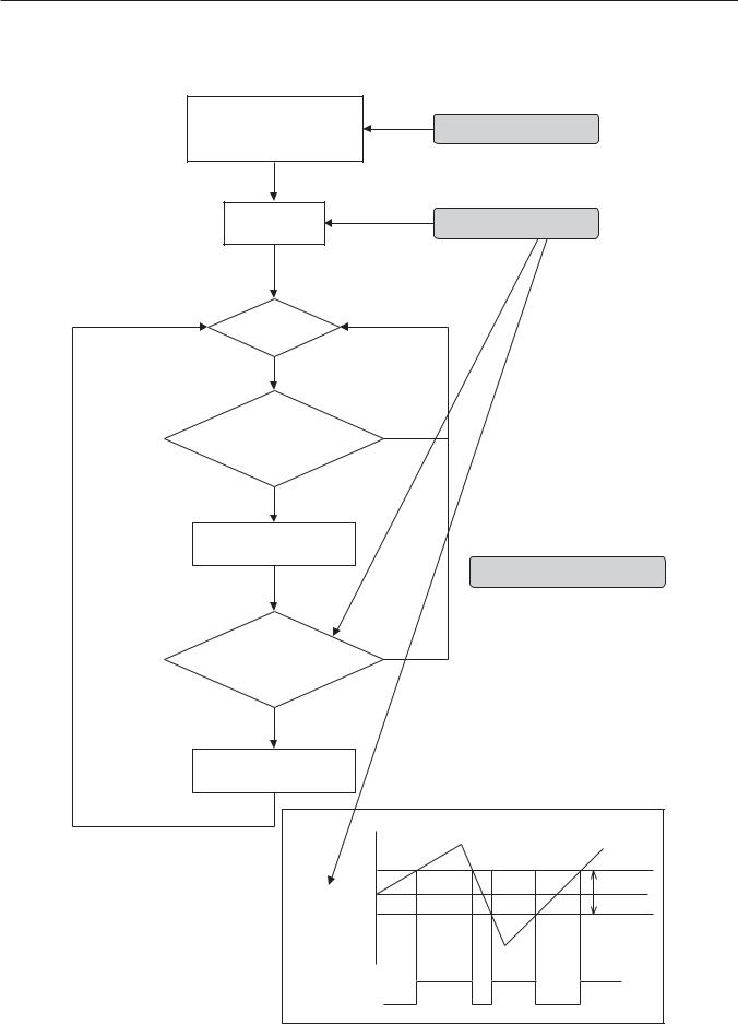
Flowchart of 12 Modes Function
Mode “00”
Set the Focus Position
Set to the factory preset
Hysteresis.
Alarm On |
Focus Position into memory |
AE moves
Focus moves outside of the hysteresis.
*
High level signal output
* Repeat this loop until Alarm off.
Focus goes back to the previous position.
Low level signal output
Far
Hysteresis
Focus
Position
Near High
Low
20
 Loading...