


2-590-890-11(1)
DVD Home Theatre
System
Operating Instructions
DAV-DZ700FW
©2005 Sony Corporation
WARNING
To prevent fire or shock hazard, do not expose the unit to rain or moisture.
Do not install the appliance in a confined space, such as a bookcase or built-in cabinet.
To prevent fire, do not cover the ventilation of the apparatus with news papers, table-cloths, curtains, etc. And don’t place lighted candles on the apparatus.
To prevent fire or shock hazard, do not place objects filled with liquids, such as vases, on the apparatus.
Don’t throw away the battery with general house waste, dispose of it correctly as chemical waste.
This appliance is classified as a CLASS 1 LASER product. This marking is located on the rear of the unit.
Precautions
Safety
•If anything falls into the cabinet, unplug the unit and have it checked by qualified personnel before operating it any further.
•The unit is not disconnected from the AC power source (mains) as long as it is connected to the wall outlet (mains), even if the unit itself has been turned off.
•Unplug the unit from the wall outlet if you do not intend to use it for an extended period of time. To disconnect the cord, pull it out by the plug, never by the cord.
Installing
•Allow adequate air circulation to prevent internal heat buildup.
•Do not place the unit on surfaces (rugs, blankets, etc.) or near materials (curtains, draperies) that may block the ventilation slots.
•Do not install the unit near heat sources such as radiators, or air ducts, or in a place subject to direct sunlight, excessive dust, mechanical vibration, or shock.
•Do not install the unit in an inclined position. It is designed to be operated in a horizontal position only.
•Keep the unit and discs away from equipment with strong magnets, such as microwave ovens, or large loudspeakers.
•Do not place heavy objects on the unit.
•If the unit is brought directly from a cold to a warm location, moisture may condense inside the DVD Home Theatre System and cause damage to the lenses. When you first install the unit, or when you move it from a cold to a warm location, wait for about 30 minutes before operating the unit.
Disposal of Old Electrical & Electronic Equipment (Applicable in the European Union and other European countries with separate collection systems)
 This symbol on the product or on its packaging indicates that this product shall not be treated as household waste. Instead
it shall be handed over to the applicable collection point for the recycling of electrical and electronic equipment. By ensuring this product is disposed of correctly, you will help prevent potential negative consequences for the environment and human health, which could otherwise be caused by inappropriate waste handling of this product. The recycling of materials will help to conserve natural resources. For more detailed information about recycling of this product, please contact your local city office, your household waste disposal service or the shop where you purchased the product.
2GB

Welcome!
Thank you for purchasing Sony DVD Home Theatre System. Before operating this system, please read this manual thoroughly and retain it for future reference.
3GB

Table of Contents |
|
Welcome! ................................................ |
3 |
About This Manual ................................. |
6 |
This System Can Play the Following |
|
Discs ................................................. |
6 |
Guide to the Control Menu Display...... |
10 |
Getting Started |
|
Unpacking ............................................. |
13 |
Inserting Batteries into the Remote....... |
13 |
Hookup Overview ................................. |
14 |
Step 1: Speaker System Hookup........... |
15 |
Step 2: Antenna (Aerial) Hookup ......... |
25 |
Step 3: TV Hookup ............................... |
26 |
Step 4: Other Component Hookup........ |
30 |
Step 5: Connecting the AC Power Cord |
|
(Mains Lead)................................... |
32 |
Step 6: Turning off |
|
the Demonstration........................... |
32 |
Step 7: Adjusting the Wireless |
|
System ............................................ |
33 |
Step 8: Performing the Quick Setup ..... |
35 |
Speaker Setup........................................ |
37 |
Playing Discs |
|
Playing Discs ........................................ |
39 |
Using the DVD’s Menu ........................ |
43 |
Selecting [ORIGINAL] or [PLAY LIST] |
|
on a DVD-RW ................................ |
44 |
Selecting a Playback Area for a Super |
|
Audio CD........................................ |
44 |
Playing VIDEO CDs with PBC Functions |
|
(Ver.2.0).......................................... |
45 |
(PBC Playback) |
|
About MP3 Audio Tracks and JPEG |
|
Image Files ..................................... |
46 |
Playing DATA CDs with MP3 Audio |
|
Track and JPEG Image Files .......... |
48 |
Playing Audio Tracks and Images as a |
|
Slide Show with Sound................... |
50 |
Enjoying DivX® Videos....................... |
52 |
Adjusting the Delay Between the Picture |
|
and Sound ....................................... |
54 |
(A/V SYNC) |
|
Searching for a Particular Point on |
|
a Disc.............................................. |
55 |
(Scan, Slow-motion Play, Freeze |
|
Frame) |
|
Searching for a Title/Chapter/Track/ |
|
Scene, etc........................................ |
56 |
Searching by Scene............................... |
58 |
(Picture Navigation) |
|
Viewing Information About the Disc ... |
59 |
Sound Adjustments |
|
Changing the Sound ............................. |
63 |
Enjoying Surround Sound by Using Sound |
|
Field................................................ |
65 |
Enjoying TV or VCR Sound from All |
|
Speakers ......................................... |
68 |
Using the Sound Effect......................... |
68 |
Using Various Additional |
|
Functions |
|
Changing the Angles ............................ |
70 |
Displaying the Subtitles........................ |
70 |
Locking Discs ....................................... |
71 |
(CUSTOM PARENTAL |
|
CONTROL, PARENTAL |
|
CONTROL) |
|
Other Operations |
|
Controlling the TV with the Supplied |
|
Remote ........................................... |
75 |
Using the THEATRE SYNC |
|
Function.......................................... |
76 |
Enjoying the Sound of Other |
|
Components.................................... |
77 |
Enjoying Multiplex Broadcast |
|
Sound.............................................. |
78 |
(DUAL MONO) |
|
Enjoying the Radio ............................... |
79 |
Using the Radio Data System (RDS) ... |
81 |
Using the Sleep Timer .......................... |
81 |
Changing the Brightness of the Front |
|
Panel Display.................................. |
82 |
Returning to the Default Settings ......... |
82 |
4GB
Settings and Adjustments |
|
Using the Setup Display........................ |
83 |
Setting the Display or Sound Track |
|
Language ........................................ |
84 |
[LANGUAGE SETUP] |
|
Settings for the Display......................... |
85 |
[SCREEN SETUP] |
|
Custom Settings .................................... |
86 |
[CUSTOM SETUP] |
|
Settings for the Speakers....................... |
87 |
[SPEAKER SETUP] |
|
Additional Information |
|
Precautions ............................................ |
90 |
Notes about the Discs............................ |
91 |
Troubleshooting .................................... |
91 |
Self-diagnosis Function ........................ |
94 |
(When letters/numbers appear in |
|
the display) |
|
Specifications ........................................ |
95 |
Glossary ................................................ |
96 |
Language Code List .............................. |
99 |
Index to Parts and Controls................. |
100 |
DVD Setup Display List ..................... |
105 |
AMP Menu List .................................. |
106 |
Index ................................................... |
107 |
5GB
About This Manual
•The instructions in this manual describe the controls on the remote. You can also use the controls on the system if they have the same or similar names as those on the remote.
•The Control Menu items may be different depending on the area.
•“DVD” may be used as a general term for DVD VIDEOs, DVD+RWs/DVD+Rs, and DVD-RWs/DVD-Rs.
•Measurements are expressed in feet (ft) for North American models.
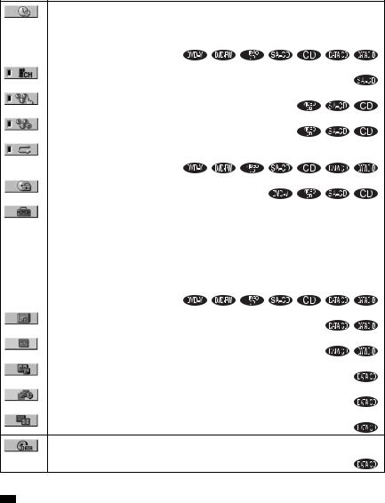
•The following symbols are used in this manual.
Symbol Meaning
Functions available for DVD VIDEOs, DVD-Rs/DVD-RWs in video mode, and DVD+Rs/ DVD+RWs
Functions available for DVD-RWs in VR (Video Recording) mode
Functions available for VIDEO
CDs (including Super VCDs or CD-
Rs/CD-RWs in video CD format or
Super VCD format)
Functions available for Super Audio
CDs
Functions available for music CDs or CD-Rs/CD-RWs in music CD format
Functions available for DATA CDs (CD-ROMs/CD-Rs/CD-RWs containing MP3*1 audio tracks, JPEG image files, and DivX*2*3 video files)
Functions available for DATA
DVDs (DVD-Rs/DVD-RWs/
DVD+Rs/DVD+RWs) containing
DivX*2*3 video files
*1 MP3 (MPEG1 Audio Layer 3) is a standard format defined by ISO/MPEG which compresses audio data.
*2 DivX® is a video file compression technology, developed by DivXNetworks, Inc.
*3 DivX, DivX Certified, and associated logos are trademarks of DivXNetworks, Inc. and are used under license.
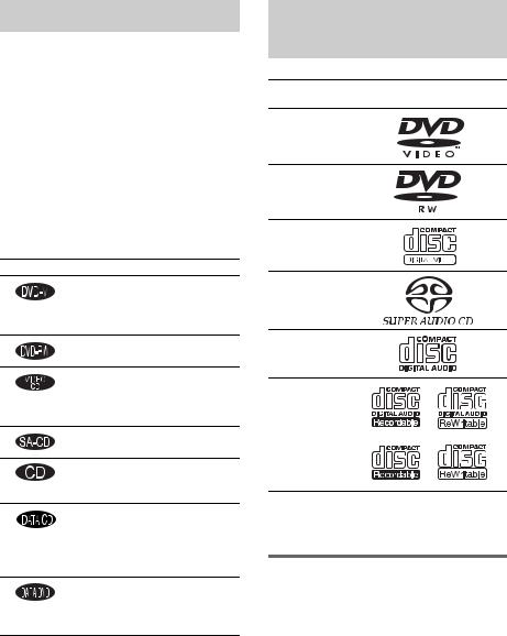
This System Can Play the
Following Discs
Format of
Disc logo
discs
DVD VIDEO
DVD-RW
VIDEO CD
Super Audio
CD
Audio CD
CD-R/CD-RW (audio data) (MP3 files) (JPEG files)
The “DVD VIDEO” logo and “DVD-RW” logo are trademarks.
Note about CDs/DVDs
The system can play CD-ROMs/CD-Rs/CD- RWs recorded in the following formats:
–audio CD format
–video CD format
–MP3 audio tracks, JPEG image files, and DivX video files of format conforming to ISO 9660 Level 1/Level 2, or its extended format, Joliet
6GB

The system can play DVD-ROMs/DVD+RWs/ DVD-RWs/DVD+Rs/DVD-Rs recorded in the following formats:
–DivX video files of format conforming to UDF.
Example of discs that the system cannot play
The system cannot play the following discs:
•CD-ROMs/CD-Rs/CD-RWs other than those recorded in the formats listed on page 6
•CD-ROMs recorded in PHOTO CD format
•Data part of CD-Extras
•DVD Audios
•DVD-RAMs
Also, the system cannot play the following discs:
•A DVD VIDEO with a different region code (page 8, 98).
•A disc that has a non-standard shape (e.g., card, heart).
•A disc with paper or stickers on it.
•A disc that has the adhesive of cellophane tape or a sticker still left on it.
Notes about CD-R/CD-RW/DVD-R/ DVD-RW/DVD+R/DVD+RW
In some cases, CD-R/CD-RW/DVD-R/DVD-RW/ DVD+R/DVD+RW cannot be played on this system due to the recording quality or physical condition of the disc, or the characteristics of the recording device and authoring software.
The disc will not play if it has not been correctly finalized. For more information, see the operating instructions for the recording device.
Note that discs created in the Packet Write format cannot be played.
Music discs encoded with copyright protection technologies
This product is designed to play back discs that conform to the Compact Disc (CD) standard. Recently, various music discs encoded with copyright protection technologies are marketed by some record companies. Please be aware that among those discs, there are some that do not conform to the CD standard and may not be playable by this product.
Note on DualDisc
This product is designed to playback discs that conform to the Compact Disc (CD) standard. A DualDisc is a two sided disc product which mates DVD recorded material on one side with digital audio material on the other side. Please be aware that the audio side of a DualDisc may not play on this product because these discs do not conform to the CD standard. “DualDisc” is a trademark of the Recording Industry Association of America (RIAA).
Note on PBC (Playback Control) (VIDEO CDs)
This system conforms to Ver. 1.1 and Ver. 2.0 of VIDEO CD standards. You can enjoy two kinds of playback depending on the disc type.
Disc type |
You can |
VIDEO CDs |
Enjoy video playback (moving |
without PBC |
pictures) as well as music. |
functions |
|
(Ver. 1.1 discs) |
|
|
|
VIDEO CDs |
Play interactive software using |
with PBC |
menu screens displayed on the |
functions |
TV screen (PBC Playback), in |
(Ver. 2.0 discs) |
addition to the video playback |
|
functions of Ver. 1.1 discs. |
|
Moreover, you can play high- |
|
resolution still pictures, if they |
|
are included on the disc. |
|
|
About Multi Session CD
•This system can play Multi Session CDs when an MP3 audio track is contained in the first session. Any subsequent MP3 audio tracks recorded in later sessions can also be played back.
•This system can play Multi Session CDs when a JPEG image file is contained in the first session. Any subsequent JPEG image files recorded in later sessions can also be played back.
•If audio tracks and images in music CD format or video CD format are recorded in the first session, only the first session will be played back.
7GB
About the Super Audio CD
Super Audio CD is a new high-quality audio disc standard where music is recorded in the DSD (Direct Stream Digital) format (conventional CDs are recorded in the PCM format). The DSD format, using a sampling frequency 64 times higher than that of a conventional CD, and with 1-bit quantization, achieves both a wide frequency range and a wide dynamic range across the audible frequency range, and so provides music reproduction extremely faithful to the original sound.
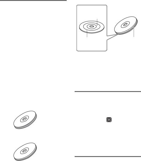
Types of Super Audio CDs
There are two types of discs, depending on the Super Audio CD layer and CD layer combination.
•Super Audio CD layer: A high-density signal layer for Super Audio CD
•CD layer*1: A layer that is readable by a conventional CD player
Single layer disc
(a disc with a single Super Audio CD layer)
 Super Audio CD
layer
Hybrid disc*2
(a disc with a Super Audio CD layer and a CD layer)
 CD layer*3
 Super Audio CD
layer*3
A Super Audio CD layer consists of the 2 channel area or the multi-channel area.
•2 channel area: An area in which 2 channel stereo tracks are recorded
•Multi-channel area: An area in which multichannel (up to 5.1 channels) tracks are recorded
2 channel area*4
Multi channel area*4 |
Super Audio CD |
|
layer |
*1 You can play the CD layer on a conventional CD player.
*2 Since both layers are on one side, it is not necessary to turn the disc over.
*3 To select a layer, see “Selecting a Playback Area for a Super Audio CD” (page 44).
*4 To select an area, see “Selecting a Playback Area for a Super Audio CD” (page 44).
Region code
Your system has a region code printed on the back of the unit and will only play DVDs labeled with the same region code.
DVD VIDEOs labeled ALL will also play on this system.
If you try to play any other DVD VIDEO, the message [Playback prohibited by area limitations.] will appear on the TV screen. Depending on the DVD VIDEO, no region code indication may be given even though playing the DVD VIDEO is prohibited by area restrictions.
Note on playback operations of DVDs and VIDEO CDs
Some playback operations of DVDs and VIDEO CDs may be intentionally set by software producers. Since this system plays DVDs and VIDEO CDs according to the disc contents the software producers designed, some playback features may not be available. Also, refer to the instructions supplied with the DVDs or VIDEO CDs.
8GB

Copyrights
This product incorporates copyright protection technology that is protected by U.S. patents and other intellectual property rights. Use of this copyright protection technology must be authorized by Macrovision, and is intended for home and other limited viewing uses only unless otherwise authorized by Macrovision. Reverse engineering or disassembly is prohibited.
This system incorporates with Dolby*1 Digital and Dolby Pro Logic (II) adaptive matrix surround decoder and the DTS*2 Digital Surround System.
*1 Manufactured under license from Dolby Laboratories.
“Dolby,” “Pro Logic,” and the double-D symbol are trademarks of Dolby Laboratories.
*2 Manufactured under license from Digital Theater Systems, Inc.
“DTS” and “DTS Digital Surround” are trademarks of Digital Theater Systems, Inc.
9GB
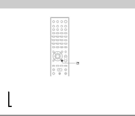
Guide to the Control Menu Display
DISPLAY
Use the Control Menu to select a function and to view related information. Press  DISPLAY repeatedly to turn on or change the Control Menu display as follows:
, Control Menu display 1
m
Control Menu display 2 (appears for certain discs only)
m
Control Menu display off
Control Menu display
The Control Menu display 1 and 2 will show different items depending on the disc type. For details about each item, see the pages in parentheses.
10GB
Example: Control Menu display 1 when playing a DVD VIDEO.
Currently playing title number*1
Currently playing chapter number*2
Total number of titles*1
Total number of chapters*2 |
Playback status |
(N Playback, X |
|
Control Menu items |
Pause, |
|
x Stop, etc.) |
|
1 2 ( 2 7 ) |
|
|
|
1 8 ( 3 4 ) |
DVD VIDEO |
|
|
T |
1 : 3 2 : 5 5 |
|
Selected item |
OFF |
|
|
|
OFF |
|
|
|
DISC |
|
|
|
TITLE |
|
|
|
CHAPTER |
|
|
Function name of |
|
|
|
selected Control |
REPEAT |
|
|
Menu item |
|
ENTER |
Quit: DISPLAY |
Type of disc being played*3
Playing time*4
Current setting
Options
Operation message
*1 Displays the scene number for VIDEO CDs (PBC is on), track number for VIDEO CDs/Super Audio CDs/CDs, album number for DATA CDs. DivX video album number for DATA DVDs/DATA CDs.
*2 Displays the index number for VIDEO CDs/Super Audio CDs, MP3 audio track number, or JPEG image file number for DATA CDs. DivX video file number for DATA DVDs/DATA CDs.
*3 Displays Super VCD as “SVCD.” Displays “MP3” in the Control Menu display 1 or “JPEG” in the Control Menu 2 for DATA CDs.
*4 Displays the date for JPEG files.
To turn off the display
Press  DISPLAY.
List of Control Menu items
Item |
Item Name, Function, Relevant Disc Type |
[TITLE] (page 56)/[SCENE] (page 56)/[TRACK] (page 56)
Selects the title, scene, or track to be played.
[CHAPTER] (page 56)/[INDEX] (page 56)
Selects the chapter or index to be played.
[INDEX] (page 56)
Displays the index and selects the index to be played.
[TRACK] (page 56)
Selects the track to be played.
[ORIGINAL/PLAY LIST] (page 44)
Selects the type of titles (DVD-RW) to be played, the [ORIGINAL] one, or an edited [PLAY LIST]. 
continued
11GB
|
|
|
[TIME/TEXT] (page 57) |
|
|
|
Checks the elapsed time and the remaining playback time. |
|
|
|
Input the time code for picture and music searching. |
|
|
|
Displays the DVD/CD text or the MP3 track name. |
|
|
|
|
|
|
|
[MULTI/2CH] (page 44) |
|
|
|
Selects the playback area on Super Audio CDs when available. |
|
|
|
|
|
|
|
[PROGRAM] (page 41) |
|
|
|
Selects the track to play in the order you want. |
|
|
|
|
|
|
|
[SHUFFLE] (page 42) |
|
|
|
Plays the track in random order. |
|
|
|
|
|
|
|
[REPEAT] (page 42) |
|
|
|
Plays the entire disc (all titles/all tracks/all albums) repeatedly or one title/chapter/track/album |
|
|
|
repeatedly. |
|
|
|
|
|
|
|
[PARENTAL CONTROL] (page 71) |
|
|
|
Sets to prohibit playback on this system. |
|
|
|
|
|
|
|
[SETUP] (page 83) |
|
|
|
|
|
|
|
[QUICK] Setup (page 35) |
|
|
|
|
|
|
|
Use Quick Setup to choose the desired language of the on-screen display, the aspect ratio of |
|
|
|
the TV, and the size of the speakers you are using. |
|
|
|
[CUSTOM] Setup |
|
|
|
In addition to the Quick Setup setting, you can adjust various other settings. |
|
|
|
[RESET] |
|
|
|
Returns the settings in [SETUP] to the default setting. |
|
|
|
|
|
|
|
[ALBUM] (page 56) |
|
|
|
Selects the album to be played. |
|
|
|
|
|
|
|
[FILE] (page 56) |
|
|
|
Selects the JPEG image file or DivX video file to be played. |
|
|
|
|
* |
[DATE] (page 61) |
||
|
|
|
Displays the date the picture was taken by a digital camera. |
|
|
|
|
* |
[INTERVAL] (page 51) |
||
|
|
|
Specifies the duration for which the slides are displayed on the screen. |
|
|
|
|
* |
[EFFECT] (page 52) |
||
|
|
|
Selects the effects to be used for changing slides during a slide show. |
*[MODE (MP3, JPEG)] (page 50)
Selects the data type; MP3 audio track (AUDIO), JPEG image file (IMAGE) or both
(AUTO) to be played when playing a DATA CD.
* These items are not displayed when playing a DATA CD with DivX video file.
•The Control Menu icon indicator lights up in green  t
t  when you select any item except [OFF] ([PROGRAM], [SHUFFLE], [REPEAT] only). The [ORIGINAL/PLAY LIST] indicator lights up in green when
you select [PLAY LIST] (default setting). The [MULTI/2CH] indicator lights up in green when you select the multi-channel playback area on a Super Audio CD.
12GB
Getting Started
Unpacking
Check that you have the following items:
•Speakers (5)
•Subwoofer (1)
• Posts (long × 4, short × 4)
•Bases (4)
•Terminal covers (4)
•Screws (20)
•Surround amplifier (1)
•IR transmitter* (1)
•IR receiver* (1)
•IR receiver stand (1)
•Speaker base (1)
•AM loop antenna (aerial) (1)
•FM wire antenna (aerial) (1)
•Speaker cords (5 m × 6)
(16.5 ft. × 6)
•Remote Commander (remote) (1)
•Size AA (R6) batteries (2)
•Wall-mount pads
•Operating Instructions
•Speaker and TV connections (card) (1)
*The cords of the IR transmitter and IR receiver are for this system only. You cannot use a commercially available extension cord.
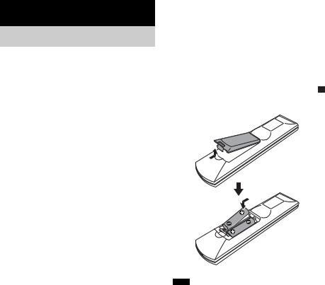
Inserting Batteries into |
|
|
|
|
|
the Remote |
|
Getting |
You can control the system using the supplied |
||
remote. Insert two Size AA (R6) batteries by |
Started |
|
|
||
matching the 3 and # ends on the batteries to |
|
|
the markings inside the compartment. When |
|
|
using the remote, point it at the remote sensor |
|
|
on the system. |
|
|
Note
•Do not leave the remote in an extremely hot or humid place.
•Do not use a new battery with an old one.
•Do not drop any foreign object into the remote casing, particularly when replacing the batteries.
•Do not expose the remote sensor to direct light from the sun or lighting apparatus. Doing so may cause a malfunction.
•If you do not intend to use the remote for an extended period of time, remove the batteries to avoid possible damage from battery leakage and corrosion.
13GB

Hookup Overview
Perform all connections and settings by following Steps 1 to 8.
“Step 1: Speaker System Hookup” (page 15)
“Step 2: Antenna (Aerial) Hookup” (page 25)
“Step 3: TV Hookup” (page 26)
“Step 4: Other Component Hookup” (page 30)
“Step 5: Connecting the AC Power Cord (Mains Lead)” (page 32) “Step 6: Turning off the Demonstration” (page 32)
“Step 7: Adjusting the Wireless System” (page 33) “Step 8: Performing the Quick Setup” (page 35)
Video signal is sent to the TV, and is output from the TV screen; audio signals are processed by this system and output from the speakers of this system. You can also enjoy sound of other sources, such as TV programs, in addition to DVDs or CDs.
14GB
Step 1: Speaker System Hookup
Connect the supplied speaker system using the supplied speaker cords by matching the colors of the jacks to those of the cords. Do not connect any speakers other than those supplied with this system. To obtain the best possible surround sound, specify the speaker parameters (distance, level, etc.) on page 87.
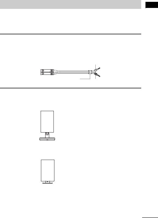
Required cords
Speaker cords
The connector and the color tube of the speaker cords are the same color as the label of the jacks to be connected.
Gray
(+)
(+)
(–)
(–)
Color tube
Black
Required equipments for the wireless system
IR transmitter
Transmits the sound by the infrared ray. Connect it to the system.
IR receiver
Receive the sound by the infrared ray. Connect it to the surround amplifier.
Started Getting
continued
15GB
When using the IR receiver stand, attach the stand so that both delta marks on the IR receiver and stand are aligned.
 IR receiver
Delta marks
 IR receiver stand
Surround amplifier
Receive the sound from the IR receiver and send to the surround speakers. Connect the surround speakers and the IR receiver to the surround amplifier.
POWER/ON LINE
POWER
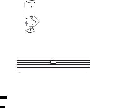
Attaching the speaker stand to the speaker
Before connecting the speakers, attach the speaker stand to the speaker.
Note
•Spread a cloth on the floor to avoid damaging the floor.
•You can use the speaker without the speaker stand by installing it on the wall (page 22).
1 Insert the post into the base.
16GB
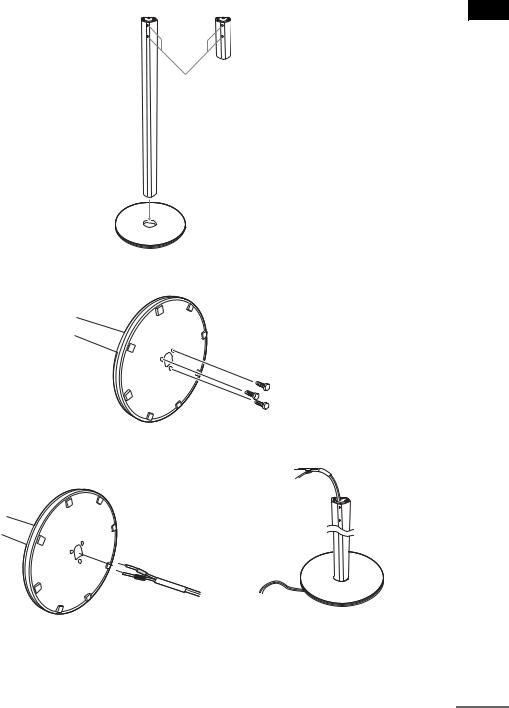
The long post is for floor use, the short post is for tabletop use.
Post (long) |
or |
Post (short) |
|
||
|
Screw holes |
|
Base
2 Secure the base to the post by screws.
Bottom of the base
Screws (3)
3 Draw the speaker cord through the hole on the base, then stand it up.
Bottom of the base
,
Speaker cord
Started Getting
continued
17GB
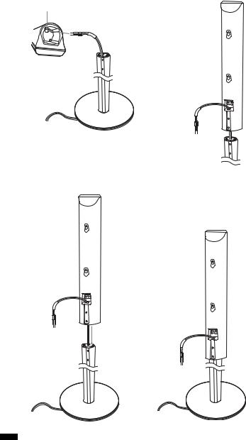
4 Draw the speaker cord through the hole on the speaker.
Hole
Speaker
Speaker cord
Speaker
,
5 Mount the speaker on the post.
,
Note
•Do not catch the speaker cord between the speaker and the post.
•Do not drop the speaker when mounting.
18GB
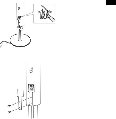
6 Connect the speaker cord to the speaker, then adjust the length of the speaker cord.
Started Getting
Adjust the length of the speaker cord.
7 Attach the terminal cover to the speaker by screws.
Terminal cover
Screws (2)
19GB

Connecting the speakers
Front speaker (R) |
Center speaker |
Front speaker (L) |
|||||
|
|
|
|
|
|
|
|
|
|
|
|
|
|
|
|
|
|
|
|
|
|
|
|
Rear side of the front speaker
Rear side of the front speaker
|
|
|
|
|
COMPONENT VIDEO OUT |
DVD ONLY |
EURO AV |
|
|
|
|
|
|
Y |
PB/CB |
PR/CR |
|
FRONT R |
FRONT L |
CENTER |
WOOFER |
COAXIAL |
OPTICAL |
|
|
OUTPUT(TO TV) |
DIGITAL IN |
DIGITAL IN |
|
|
|||||
|
|
|
|
|
R AUDIO IN L |
VIDEO IN |
|
|
|
|
|
|
SAT |
VIDEO |
|
|
|
SPEAKER
DIR-T1
IR transmitter
IR receiver
Subwoofer |
|
Rear side of |
Rear side of |
the surround |
the surround |
speaker |
speaker |
|
SPEAKER |
DIR-R2 |
|
SURROUND L SURROUND R |
|
Surround speaker (L) |
Surround amplifier |
Surround speaker (R) |
20GB
Note |
|
|
|
• Do not set the speakers in an inclined position. |
|
||
• Do not place the speakers in locations that are: |
Getting |
||
– Extremely hot or cold |
|||
|
|||
– Dusty or dirty |
|
||
– Very humid |
Started |
||
– Subject to vibrations |
|||
|
|||
– Subject to direct sunlight |
|
||
• Use caution when placing the speakers and/or speaker stands (not supplied) that are attached with the speakers on |
|
||
a specially treated (waxed, oiled, polished, etc.) floor, as staining or discoloration may result. |
|
||
• When cleaning, use a soft cloth such as a cleaning cloth for glasses. |
|
||
• Do not use any type of abrasive pad, scouring powder, or solvent such as alcohol or benzine. |
|
||
• Do not lean or hang on the speaker, as the speaker may fall down. |
|
||
Notes on placing IR transmitter and IR receiver
•Do not install the IR receiver in a place exposed to direct sunlight or strong light such as an incandescent lamp.
•The cords of the IR transmitter and IR receiver are for this system only. You cannot use a commercially available extension cord.
Notes on placing the surround amplifier and speaker base
•Do not step and place objects other than supplied speakers on the surround amplifier and speaker base.
•When you install the speaker on the surround amplifier or speaker base, make sure the speaker is properly stacked.
To connect the speaker cords
Connect the speaker cords after bending the bare wire at the end of the insulation. This prevents the speaker insulation from being inserted in the speaker terminal.
Note
• Do not catch the speaker cord insulation in the SPEAKER jack.
Avoiding short-circuiting the speakers
Short-circuiting of the speakers may damage the system. To prevent this, be sure to follow these precautions when connecting the speakers. Make sure the bare wire of each speaker cord does not touch another speaker terminal or the bare wire of another speaker cord.
21GB
Examples of poor conditions of the speaker cord
Stripped speaker cord is |
Stripped cords are touching each |
touching another speaker |
other due to excessive removal of |
terminal. |
insulation. |
After connecting all the components, speakers, and AC power cord (mains lead), output a test tone to check that all the speakers are connected correctly. For details on outputting a test tone, see page 89. If no sound is heard from a speaker while outputting a test tone, or a test tone is output from a speaker other than the one currently displayed on the Setup Display, the speaker may be short-circuited. If this happens, check the speaker connection again.
Note
•Be sure to match the speaker cord to the appropriate terminal on the components: 3 to 3, and # to #. If the cords are reversed, the sound will lack bass and may be distorted.
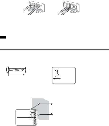
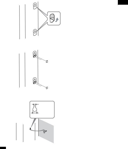
Installing the speakers on the wall
1 Prepare screws (not supplied) that are suitable for the hole on the back of each speaker. See the illustrations below.
4 mm (5/ inch) |
4.6 mm |
32 |
(3/ inch) |
|
|
|
16 |
25 mm (1 inch) |
10 mm |
|
(13/32 inch) |
2 Fasten the screws to the wall.
The screws should protrude 7 to 8 mm (9/32 to 11/32 inch).
165 mm (6 1/2 inch)
7 to 8 mm
(9/32 to 11/32 inch)
Hole on the back of the speaker
3 Peel the seals off the two screw points on the rear of the speaker.
22GB
Started Getting
4 Attach the wall-mount pads on the rear side of the speaker.
Wall-mount pads
(7 × 7 mm, 3 mm thick)
(9/32 × 9/32 inch, 1/8 inch thick)
5 Hang the speakers on the screws.
4.6 mm (3/16 inch)
10 mm (13/32 inch)
Hole on the back of the speaker
Note
•Use screws that are suitable for the wall material and strength. As a plaster board wall is especially fragile, attach the screws securely to a beam and fasten them to the wall. Install the speakers on a vertical and flat wall where reinforcement is applied.
•Contact a screw shop or installer regarding the wall material or screws to be used.
•Sony is not responsible for accident or damage caused by improper installation, insufficient wall strength or improper screw installation, natural calamity, etc.
23GB
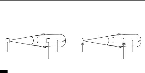
About the wireless system
This wireless system adopts the Digital Infrared Audio Transmission system (page 96). The following diagram indicates the infrared transmission area (the range that the infrared rays can reach).
Top view |
|
Side view |
|
Infrared signal |
|
|
Infrared signal |
10 |
|
|
10 |
10 |
|
|
10 |
IR transmitter |
Approx. 10m |
IR transmitter |
Approx. 10m |
IR receiver |
|
|
IR receiver |
Note
•Do not install the IR receiver in a place exposed to direct sunlight or strong light such as an incandescent lamp.
•Do not use the IR transmitter or IR receiver that is not supplied with the system.
24GB
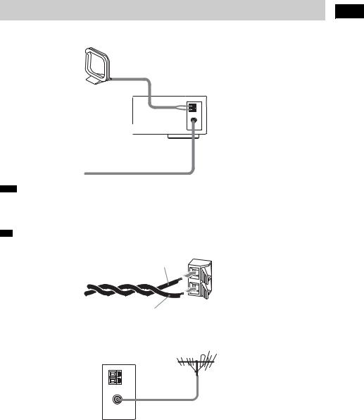
Step 2: Antenna (Aerial) Hookup
Connect the supplied AM/FM antennas (aerials) for listening to the radio.
AM loop antenna (aerial)
FM wire antenna (aerial)
Note
•To prevent noise pickup, keep the AM loop antenna (aerial) away from the system and other components.
•Be sure to fully extend the FM wire antenna (aerial).
•After connecting the FM wire antenna (aerial), keep it as horizontal as possible.
•When you connect the supplied AM loop antenna (aerial), cord (A) or cord (B) can be connected to either terminal.
A
B
•If you have poor FM reception, use a 75-ohms coaxial cable (not supplied) to connect the system to an outdoor FM antenna (aerial) as shown below.
System
Outdoor FM antenna (aerial)
Started Getting
25GB
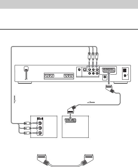
Step 3: TV Hookup
First, perform the video connection, and then audio connection.
With your TV’s audio output connected to this system, you can listen to TV sound through the system speakers.
Connecting the video cords
Sends a played back DVD image to a TV.
|
|
|
|
|
To COMPONENT |
|
|
|
|
|
|
VIDEO OUT |
|
|
|
|
COMPONENT VIDEO OUT DVD ONLY |
EURO AV |
|
|
|
|
|
Y PB/CB |
PR/CR |
|
|
|
|
|
|
|
|
AM |
FRONT R FRONT L |
CENTER WOOFER |
COAXIAL |
OPTICAL |
|
OUTPUT(TO TV) |
|
DIGITAL IN |
DIGITAL IN |
|
|
|||
|
|
|
R AUDIO IN L |
VIDEO IN |
|
|
|
|
SAT |
VIDEO |
|
|
|
|
SPEAKER |
|
|
|
|
COAXIAL |
|
|
|
|
DIR-T1 |
FM 75 |
|
|
|
|
|
|
|
|
To EURO AV T OUTPUT (TO TV)
To TV with COMPONENT |
To EURO AV |
|
t INPUT (FROM VIDEO) |
||
VIDEO IN |
||
|
||
|
EURO AV |
|
Y |
|
|
|
INPUT(FROM VIDEO) |
|
PB/CB |
|
|
PR/CR |
|
|
TV with COMPONENT |
TV |
|
VIDEO IN jacks |
|
Connect the system to your TV using the SCART (EURO AV) cord (not supplied).
Be sure to connect the SCART (EURO AV) cord to the EURO AV T OUTPUT (TO TV) jack on the system.
When you connect using the SCART (EURO AV) cord, check that the TV conforms to S video or RGB signals. If the TV conforms to S video, change the input mode of the TV to RGB signals. Refer to the operating instructions supplied with the TV to be connected.
When connecting to a TV with the COMPONENT VIDEO IN jacks
Connect a component video cord (not supplied). To use the COMPONENT VIDEO OUT jacks (Y, PB/ CB, PR/CR), your TV monitor must be equipped with via COMPONENT VIDEO IN jacks (Y,PB/CB,
26GB
PR/CR). If your TV accepts progressive format signals, you must use this connection and set the output channel of the system to progressive format (page 27).
Green
Blue
Red
When connecting to a standard 4:3 screen TV
Depending on the disc, the image may not fit your TV screen.
To change the aspect ratio, see page 85.
Does your TV accept progressive signals?
Progressive is the method for displaying TV images which reduces flickering, and sharpens the image. To display using this method, you need to connect to a TV that accepts progressive signals.
Started Getting


 FUNCTION
PROGRESSIVE
“P AUTO” or “P VIDEO” appears in the front panel display when the system outputs progressive signals.
1
2
Press FUNCTION repeatedly to select “DVD.”
Press PROGRESSIVE.
Each time you press PROGRESSIVE, the display changes as follows:
t P AUTO (PROGRESSIVE AUTO) r
P VIDEO (PROGRESSIVE VIDEO) r
INTERLACE
x P AUTO (PROGRESSIVE AUTO)
Select this setting when:
–your TV accepts progressive signals, and,
–the TV is connected to the COMPONENT VIDEO OUT jacks.
Normally select this under the above condition. This automatically detects the software type, and selects the appropriate conversion method.
Note that the picture will not be clear or no picture will appear if you select these settings when either of the above conditions is not met.
continued
27GB

x P VIDEO (PROGRESSIVE VIDEO)
Select this setting when:
–your TV accepts progressive signals, and,
–the TV is connected to the COMPONENT VIDEO OUT jacks, and,
–you want to fix the conversion method to PROGRESSIVE VIDEO for video-based software. Select this if the image is not clear when you select PROGRESSIVE AUTO.
Note that the picture will not be clear or no picture will appear if you select these settings when either of the above conditions is not met.
x INTERLACE
Select this setting when:
–your TV does not accept progressive signals, or,
–your TV is connected to jacks other than the COMPONENT VIDEO OUT jacks (EURO AV T OUTPUT (TO TV)).
About DVD software types and the conversion method
DVD software can be divided into 2 types: film-based software and video-based software. Video-based software is derived from TV, such as dramas and sit-coms, and displays images at 30 frames/60 fields per second. Film-based software is derived from film and displays images at 24 frames per second. Some DVD software contains both video and film.
In order for these images to appear natural on your screen when output in progressive format, the progressive signals need to be converted to match the type of DVD software that you are watching.
Note
•When you play video-based software in progressive signal format, sections of some types of images may appear unnatural due to the conversion process when output through the COMPONENT VIDEO OUT jacks. Even though you set to “PROGRESSIVE AUTO” or “PROGRESSIVE VIDEO,” images from the EURO AV T OUTPUT (TO TV) jack are unaffected as they are output in the interlace format.
•If you set [LINE] in [SCREEN SETUP] to [RGB] (page 86), the system switches to “INTERLACE.” This will happen even though you select “PROGRESSIVE AUTO” or “PROGRESSIVE VIDEO.”
•If you set [LINE] in [SCREEN SETUP] to [RGB] (page 86), the system outputs no component video signals.
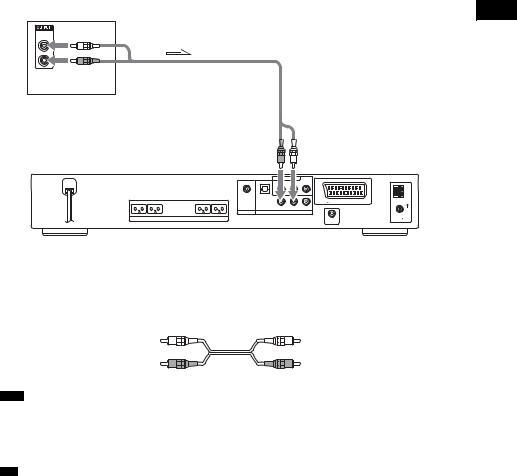
Connecting the audio cords
Outputs TV sound through the speakers of this system.
28GB
TV
AUDIO
OUT
L
R
To VIDEO (AUDIO IN)
|
|
|
|
|
COMPONENT VIDEO OUT |
DVD ONLY |
EURO AV |
|
|
|
|
|
|
|
Y |
PB/CB |
PR/CR |
|
|
|
|
|
|
|
|
|
|
|
AM |
FRONT R |
FRONT L |
CENTER |
WOOFER |
COAXIAL |
OPTICAL |
|
|
OUTPUT(TO TV) |
|
DIGITAL IN |
DIGITAL IN |
|
|
|
|||||
|
|
|
|
|
R AUDIO IN L |
VIDEO IN |
|
|
|
|
|
|
|
SAT |
VIDEO |
|
|
|
|
|
|
SPEAKER |
|
|
|
|
|
|
COAXIAL |
|
|
|
|
|
|
|
DIR-T1 |
FM 75 |
|
|
|
|
|
|
|
|
|
|
|
To connect the AUDIO OUT jacks of a TV to the VIDEO (AUDIO IN) jacks of this system
Connect a TV to the VIDEO (AUDIO IN) jacks using an audio cord (not supplied). When connecting a cord, be sure to match the color-coded sleeves to the appropriate jacks on the components.
White (L/audio)
Red (R/audio)
Note
•Be sure to make connections securely to avoid hum and noise.
•If your TV does not have AUDIO OUT jacks, you cannot output the TV sound from the speakers of this system.
•If you connect a TV to the VIDEO (AUDIO IN) jacks, other components, such as a VCR, cannot be connected (you can connect other components with the coaxial cable (not supplied) to the COAXIAL DIGITAL IN jack (page 31)).
•To listen to the TV sound, select the function by pressing FUNCTION. For details, see page 68.
•When you want to output the TV sound or stereo sound of a 2 channel source from the 6 speakers, select the “Dolby Pro Logic,” “Dolby Pro Logic II MOVIE,” or “Dolby Pro Logic II MUSIC” sound field (page 65).
Started Getting
29GB
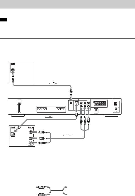
Step 4: Other Component Hookup
You can enjoy other component by connecting the VIDEO/AUDIO OUT jacks of another component.
Note
•If you connect a TV to the VIDEO jacks in Step 3 (page 26), you cannot connect other components to the system. (you can connect other components with the coaxial cable (not supplied) to the COAXIAL DIGITAL IN jack (page 31)).
Connecting the system and the other component
Outputs the other component through the speakers of this system.
Digital satellite receiver or
PlayStation 2, etc.
COAXIAL
DIGITAL
OUT
To SAT
(COAXIAL DIGITAL IN)
|
|
|
|
|
COMPONENT VIDEO OUT |
DVD ONLY |
EURO AV |
|
|
|
|
|
|
|
Y |
PB/CB |
PR/CR |
|
|
|
|
|
|
|
|
|
|
|
AM |
FRONT R |
FRONT L |
CENTER |
WOOFER |
COAXIAL |
OPTICAL |
|
|
OUTPUT(TO TV) |
|
DIGITAL IN |
DIGITAL IN |
|
|
|
|||||
|
|
|
|
|
R AUDIO IN L |
VIDEO IN |
|
|
|
|
|
|
|
SAT |
VIDEO |
|
|
|
|
|
|
SPEAKER |
|
|
|
|
|
|
COAXIAL |
|
|
|
|
|
|
|
DIR-T1 |
FM 75 |
|
|
|
|
|
|
|
|
|
|
|
To VIDEO
To VIDEO
(OPTICAL DIGITAL IN)
(VIDEO/AUDIO IN)
OPTICAL |
VIDEO |
DIGITAL |
OUT |
OUT |
|
AUDIO
OUT
L
R
VCR, Digital satellite receiver or PlayStation 2, etc.
To connect the VIDEO/AUDIO OUT jacks of other component to the VIDEO (VIDEO/AUDIO IN) jacks of this system
Connect the VCR or other components to the VIDEO (VIDEO/AUDIO IN) jacks using the video/audio cord (not supplied). When connecting a cord, be sure to match the color-coded sleeves to the appropriate jacks on the components.
 Yellow (Video)

 White (L/audio)
 Red (R/audio)
30GB
 Loading...