


RU101-RS101/BW-BW Unit DATA for Disc Professional
2-055-301-12(1)
Professional Disc for DATA Unit
User’s Guide |
|
GB |
||||
Guides de l’tilisateur |
|
|
||||
FR |
||||||
Benutzerhandbücher |
|
|
||||
DE |
||||||
Guías del usuario |
|
|
||||
ES |
||||||
Guie dell’utente |
|
|
||||
IT |
||||||
BW-RS101
BW-RU101
© 2004 Sony Corporation

Safety Regulations
Owner’s Record
The model and serial numbers are located on the bottom of the units. Record the serial number in the space provided below.
Refer to them whenever you call upon your Sony dealer regarding these products.
Model No. BW-RS101, BW-RU101 Serial No._________________________
Information
You are cautioned that any changes or modifications not expressly approved in this manual could void your authority to operate this equipment.
This equipment has been tested and found to comply with the limits for a Class B digital device, pursuant to Part 15 of the FCC Rules. These limits are designed to provide reasonable protection against harmful interference in a residential installation. This equipment generates, uses, and can radiate radio frequency energy and, if not installed and used in accordance with the instructions, may cause harmful interference to radio communications. However, there is no guarantee that interference will not occur in a particular installation. If this equipment does cause harmful interference to radio or television reception, which can be determined by turning the equipment off and on, the user is encouraged to try to correct the interference by one or more of the following measures:
-Reorient or relocate the receiving antenna.
-Increase the separation between the equipment and receiver.
-Connect the equipment into an outlet on a circuit different from that to which the receiver is connected.
-Consult the dealer or an experienced radio/TV technician for help.
These devices require shielded interface cables to comply with FCC emission limits.
If you have any questions about these products, you may call: Sony Customer Information Center 1-800-352- SONY(7669) or write to: Sony Customer Information Center 3300 Zanker Road, San Jose, CA 95134.
Declaration of Conformity
Trade Name: |
SONY |
Model No.: |
BW-RS101, BW-RU101 |
Responsible Party: |
Sony Electronics Inc. |
Address: |
16450 W. Bernardo Dr., |
|
San Diego, CA 92127 U.S.A. |
Telephone No.: |
858-942-2230 |
These devices comply with Part 15 of the FCC Rules. Operation is subject to the following two conditions: (1) These devices may not cause harmful interference, and (2) These devices must accept any interference received, including interference that may cause undesired operation.
2
WARNING
To prevent fire or shock hazard, do not expose the units to rain or moisture.
To avoid electrical shock, do not open the cabinet. Refer servicing to qualified personnel only.
Caution
As the laser beams used in the BW-RS101 and BW-RU101 are harmful to the eyes, do not attempt to disassemble the units.
Refer servicing to qualified personnel only.
The use of controls or adjustments or performance of procedures other than those specified herein may result in hazardous radiation exposure.
This label is affixed inside the units.
CAUTION CLASS 2M LASER RADIATION WHEN OPEN. DO NOT STARE INTO THE BEAM OR VIEW DIRECTLY WITH OPTICAL INSTRUMENTS.
ATTENTION RADIATIONS LASER DE CLASSE 2M EN CAS D’OUVERTURE.
NE PAS REGARDER LE FAISCEAU OU LE REGARDER DIRECTEMENT AVEC DES INSTRUMENTS OPTIQUES.
VORSICHT KLASSE 2M LASERSTRAHLUNG WENN GEÖFFNET.
NICHT IN DEN STRAHL BLICKEN, NICHT DIREKT MIT OPTISCHEN INSTRUMENTEN IN DEN STRAHL BLICKEN.
ADVARSEL LASERSTRÅLING AF KLASSE 2M VED ÅBNING. SE IKKE IND I STRÅLEN OG KIG IKKE DIREKTE PÅ DEN MED OPTISKE INSTRUMENTER.
ADVARSEL LASERSTRÅLING I KLASSE 2M NÅR ÅPEN. STIRR IKKE INN I STRÅLEN ELLER SE DIREKTE MED OPTISKE INSTRUMENTER.
VARNING KLASS 2M LASERSTRÅLING NÄR DENNA DEL ÄR ÖPPNAD. STIRRA EJ IN I STRÅLEN OCH BETRAKTA EJ STRÅLEN MED OPTISKA INSTRUMENT.
VARO! AVATTUNA LUOKAN 2M LASERSÄTEILYÄ. ÄLÄ TUIJOTA SÄTEESEEN ÄLÄKÄ. KATSO SITÄ SUORAAN OPTISEN LAITTEEN LÄPI.
This “Professional Disc for DATA” units are classified as CLASS 1 LASER PRODUCTS.
The CLASS 1 LASER PRODUCT label is located on the bottom exterior.
CLASS 1
LASER PRODUCT
LASER KLASSE 1
PRODUKT
LUOKAN 1 LASERLAITE
KLASS 1 LASER APPARAT
Caution
The mains plug on this equipment must be used to disconnect mains power. Please ensure that the socket outlets are installed near the equipment and shall be easily accessible.
Disposal of Old Electrical & Electronic Equipment (Applicable in the European Union and other European countries with separate collection systems)
This symbol on the product or on its packaging indicates that this product shall not be treated as household waste. Instead it shall
be handed over to the applicable collection
point for the recycling of electrical and electronic equipment. By ensuring this
product is disposed of correctly, you will help prevent potential negative consequences for the environment and human health, which could otherwise be caused by inappropriate waste handling of this product. The recycling of materials will help to conserve natural resources. For more detailed information about recycling of this product, please contact your local city office, your household waste disposal service or the shop where you purchased the product.
and “Professional Disc for DATA” are trademarks of |
|
|
Sony Corporation. |
|
|
GB |
||
|
•The manufacturer disclaims all responsibility for any losses incurred through malfunction or use of this product.
•The manufacturer does not warrant the security of data stored using this product. To guard accidental data loss, frequent backup of important data is highly recommended.
•Reproduction of the contents of this manual, in whole or in part, is prohibited.
3

Table of Contents |
|
|
|
Safety Regulations ...................................................... |
2 |
|
Owner’s Record .............................................................. |
2 |
|
Information...................................................................... |
2 |
|
Declaration of Conformity .............................................. |
2 |
|
WARNING ..................................................................... |
3 |
Chapter 1 |
Introduction |
|
|
Overview....................................................................... |
5 |
|
Features ........................................................................... |
5 |
|
Compatible Discs ........................................................ |
5 |
|
System Configuration ................................................. |
6 |
|
BW-RS101 System Configuration.................................. |
6 |
|
BW-RU101 System Configuration ................................. |
6 |
|
Part Location and Function ........................................ |
7 |
|
BW-RS101/BW-RU101 Front Panel .............................. |
7 |
|
BW-RS101 Rear Panel.................................................... |
8 |
|
BW-RU101 Rear Panel................................................... |
9 |
Chapter 2 |
Getting Started |
|
|
Component and Accessory Checklist ..................... |
10 |
|
BW-RS101 Accessory Checklist .................................. |
10 |
|
BW-RU101 Accessory Checklist.................................. |
11 |
|
When using the unit placed vertically ..................... |
12 |
|
Connecting the Unit .................................................. |
13 |
|
Connecting the BW-RS101........................................... |
13 |
|
Connecting the BW-RU101 .......................................... |
14 |
|
Setting Functions/SCSI ID ........................................ |
15 |
|
BW-RS101 Function Settings....................................... |
15 |
|
BW-RU101 Function Settings ...................................... |
18 |
|
Using Discs ................................................................ |
20 |
|
Inserting a Disc ............................................................. |
20 |
|
Ejecting a Disc .............................................................. |
23 |
|
What to Do when You Cannot Eject a Disc.................. |
24 |
|
About Handling Discs ............................................... |
25 |
|
How to Protect Disc Data.............................................. |
25 |
Chapter 3 Usage Precautions
Unit Usage Precautions ............................................ |
26 |
Chapter 4 Specifications
Specifications ............................................................ |
28 |
Disc Specifications........................................................ |
28 |
Specifications ................................................................ |
28 |
4

Introduction Chapter
Overview
Features
The Sony BW-RS101/BW-RU101 “Professional Disc for DATA” Unit comes with the following features.
•The “Professional Disc for DATA” external optical disc unit uses a shortwave blue violet laser with a wavelength of 405 nm.
•The powerful objective lens used for focusing the laser beam has a numerical aperture of 0.85, resulting in a track pitch of only 0.32 µm. This makes writing as much as 23.3 GB of data on one side of a disc possible.
•A 0.1 mm cover layer enables a high tilt tolerance.
•The overall thickness of the 120 mm discs is 1.2 mm and the recording layer has a cover layer of only 0.1 mm thick. This effectively increases the margin of error when the disc tilts or bends. Tilt tolerance is thus enough to enhance reliability for read/write operations.
•The BW-RS101 uses SCSI-3 (Ultra 160 LVD/SE SCSI).
•The BW-RU101 uses Hi-Speed USB (USB 2.0).
•The seek time in the CAV is 110 ms (1/3 stroke) or 200 ms (full stroke).
•In CLV mode, the high-speed spindle motor allows for a 9 MB/s write data transfer speed and a 10.8 MB/s read data transfer speed.
•In CAV, the high-speed spindle motor allows for 4.5 to 9 MB/s write data transfer speed and 4.5 to 10.8 MB/s read transfer speed.
Compatible Discs
The BW-RS101 and BW-RU101 are compatible with two types of discs.
Disc name |
Type |
Capacity |
Disc diameter |
|
|
|
|
PDDRW23 |
Rewritable |
23.3 GB |
120 mm |
|
|
|
|
PDDWO23 |
Write-once |
23.3 GB |
120 mm |
|
|
|
|
Overview 5
System Configuration
Introduction 1 Chapter
BW-RS101 System Configuration
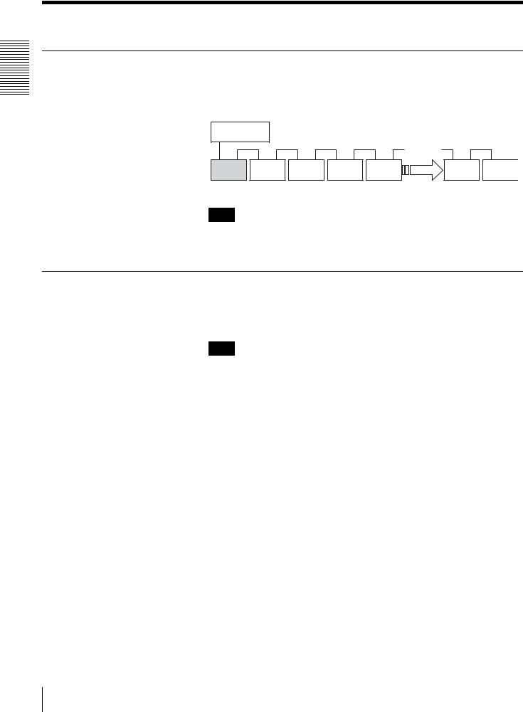
The BW-RS101 is connected to a host computer through its SCSI interface. A maximum of fifteen peripheral devices can be connected in a daisy chain on the SCSI bus. See “SCSI Cables” on page 13 for details.
Host computer
SCSI cable 12 m
ID=0 |
ID=1 |
ID=2 |
ID=3 |
ID=4 |
ID=14 |
ID=15 |
|
|
|
|
|
ID=5 |
|
BW-RS101 |
|
SCSI peripheral devices |
|
|
||
Note
The BW-RS101 supports single-ended (SE) and low-voltage differential (LVD) SCSI configurations. When a single daisy chain is both of the LVD and SE configuration, the transfer rate conforms to SE specifications.
BW-RU101 System Configuration
The BW-RU101 is connected to a host computer through its USB interface. A maximum of 127 peripheral devices can be connected to a host computer through USB Hub. See “USB Cables” on page 14 for details.
Note
The BW-RU101 complies with Hi-Speed USB (USB 2.0), which also complies to USB 1.1. Although with Hi-Speed USB the maximum transfer rate is 480 Mbps, with USB 1.1 the transfer rate conforms to the USB 1.1 specification of a maximum 12 Mbps.
6 System Configuration
Part Location and Function
This section describes the parts of the “Professional Disc for DATA” units BW-
RS101 and BW-RU101 and gives an overview of their functions.
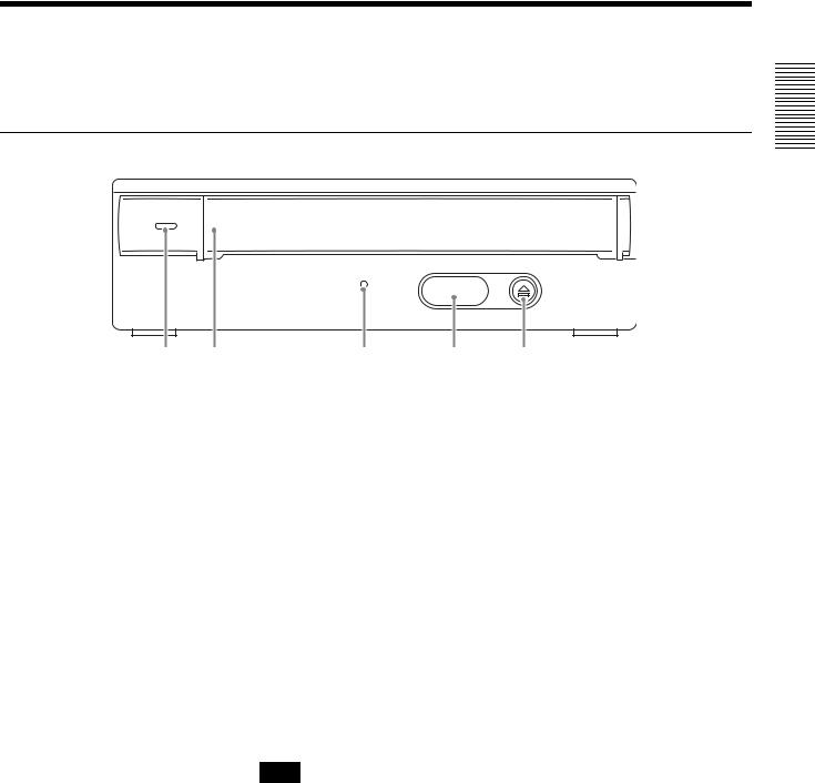
BW-RS101/BW-RU101 Front Panel
1 Chapter
|
|
|
|
Introduction |
1 |
2 |
3 |
4 |
5 |
A Power indicator
Lights green when the unit is on.
B Slot cover
When inserting a disc, open this slot cover by pulling it toward you. After inserting the disc, close the slot cover. The cover opens automatically when you eject a disc, but you need to close it manually. see “Inserting a Disc” on page 20 for details.
C Busy indicator
Alternates between green and amber when the unit is reading or writing data. Do not eject the disc when the indicator is amber.
D Emergency eject hole cover
In emergency only, remove this hole cover and then eject the disc. See “What to
Do when You Cannot Eject a Disc” on page 24 for details.
E Eject button
Press this button to eject a disc from the unit. You cannot use the eject button to eject button to eject the disc when the unit is off.
Note
If write cache is used, pressing the eject button writes data in the cache memory to the disc, and so it may take a while to eject the disc.
Part Location and Function |
7 |
|
|

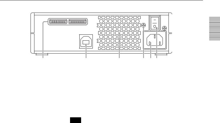
BW-RS101 Rear Panel
Introduction 1 Chapter
1 |
2 |
3 |
4 5 6 |
A Function switches
Use these switches to set the SCSI ID and unit functions. See “BW-RS101 Function Settings” on page 15 for details
B SCSI connectors
Connect SCSI cables (sold separately) to these connectors to link the host computer and/or other SCSI devices.
C Air duct
Air is sucked through the duct for cooling the unit.
Note
Make sure that you do not block the air duct or impede the air flow.
D F.GND (ground terminal)
Connect the ground terminals of other devices to the unit's frame ground.
E AC IN connector
Connect the supplied AC power cord to this connector.
F Power switch
Pressing the “ ? ” side turns on the power. To turn off the power, press the “a” side.
8 Part Location and Function
BW-RU101 Rear Panel
1
2 |
3 |
4 5 6 |
A Function switches
Use these switches to set the unit functions. See “BW-RU101 Function Settings” on page 18 for details
B  USB connector
Connect the USB cable supplied to link the host computer and/or the USB Hub.
C Air duct
Air is sucked through the duct for cooling the unit.
Note
Make sure that you do not block the air duct or impede the air flow.
D F.GND (ground terminal)
Connect the ground terminals of other devices to the unit's frame ground.
E AC IN connector
Connect the supplied AC power cord to this connector.
F Power switch
Pressing the “ ? ” side turns on the power. To turn off the power, press the “a” side.
Introduction 1 Chapter
Part Location and Function |
9 |
|
|
Getting Started Chapter
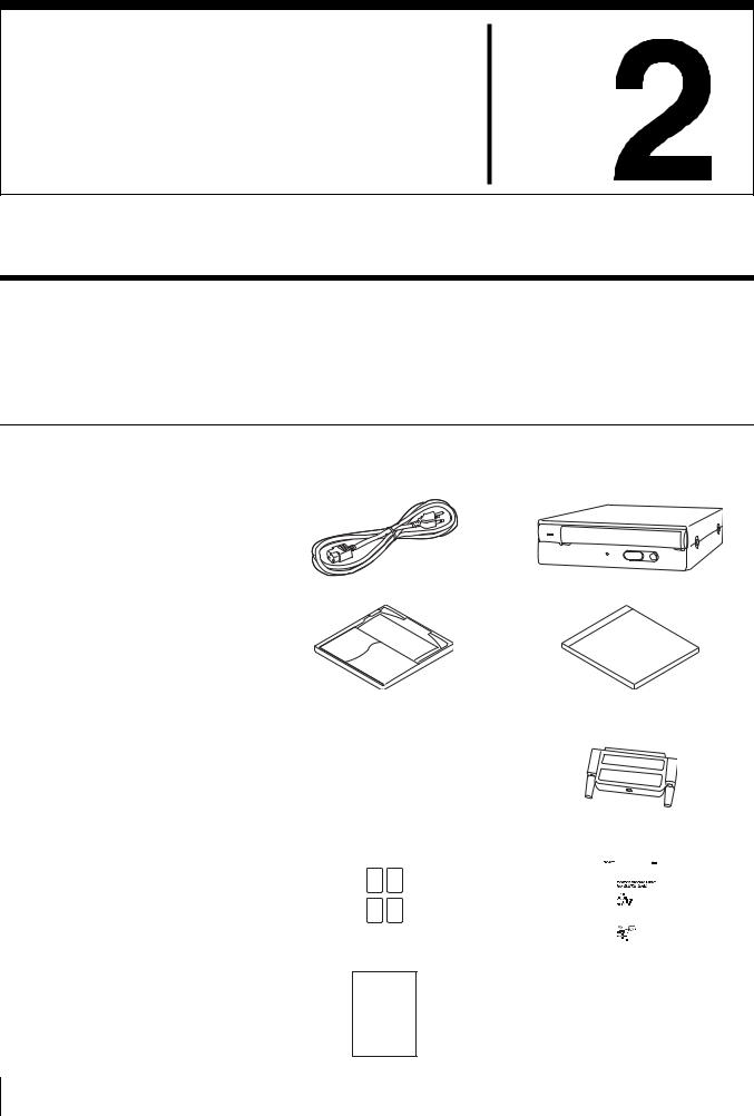
Component and Accessory Checklist
Upon opening the unit package, make sure that all the components and accessories listed below are present. If you find any missing and/or damaged items, contact your dealer.
BW-RS101 Accessory Checklist
• AC power cord |
• BW-RS101 “Professional Disc for |
|
DATA” Unit |
• Disc (PDDRW23) |
• Formatting Utility |
• Guide to Safe Use |
• LVD/SE terminator |
|
(Safety Precautions) |
|
|
|
|
|
|
|
|
• Protection cushion sheet |
• User’s guide (this document) |
|||||||||
|
|
|
|
|
|
|
|
|
|
|
|
|
|
|
|
|
|
|
|
|
|
|
|
|
|
|
|
|
|
|
|
|
|
|
|
|
|
|
|
|
|
|
|
|
|
|
|
|
|
|
|
|
|
|
|
|
|
|
|
|
|
|
|
|
|
• Warranty Card
10 Component and Accessory Checklist
BW-RU101 Accessory Checklist
• AC power cord |
• BW-RU101 “Professional Disc for |
|
DATA” Unit |
• Disc (PDDRW23) |
• Formatting Utility |
• Guide to Safe Use |
• Protection cushion sheet |
|||
(Safety Precautions) |
|
|
|
|
|
|
|
|
|
|
|
|
|
|
|
|
|
|
|
• USB 2.0 cable |
• User’s guide (this document) |
||||||
|
|
|
|
|
|
|
|
|
|
|
|
|
|
|
|
|
|
|
|
|
|
|
|
|
|
|
|
|
|
|
|
• Warranty Card
Started Getting 2 Chapter
Component and Accessory Checklist |
11 |
|
|
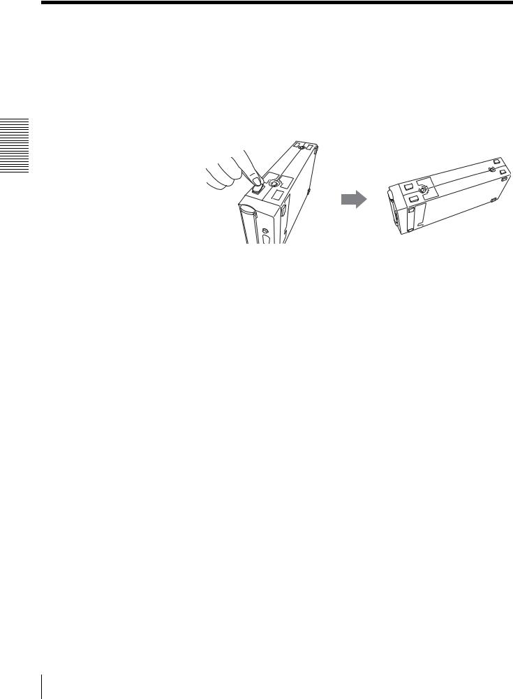
When using the unit placed vertically
Be sure to stick the supplied protection cushion sheets to the four points as illustrated bellow before using the unit. Using the unit placed vertically without sticking the cushion sheets may cause scratch the unit and/or unstable operations.
How to Stick the Protection Cushion Sheet
Stick the protection cushion sheet to the four indentations on the base of the unit.
Started Getting 2 Chapter
12 When using the unit placed vertically
Connecting the Unit
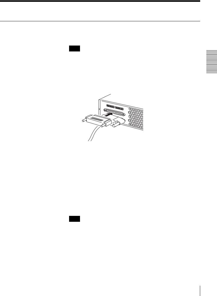
Connecting the BW-RS101
You can connect the unit to one host computer through a SCSI bus that has up to 15 devices connected in a daisy chain.
Note
Before connecting the unit, make sure to turn off the unit and all the other devices on the SCSI chain.
1 Connect a SCSI cable to the SCSI connecter of the unit to connecting a host computer or another SCSI device.
2 If the unit is the last device on the SCSI daisy chain, connect the supplied terminator to one of the SCSI connecters as illustrated below.
Started Getting 2 Chapter
3 Connect the AC power cord to the AC IN connector on the unit.
SCSI Cables
You can use a 68-signal conductor, flat cable or a 34-signal twisted cable as the LVD/SE cable. To achieve a high transfer rate, the total length of SCSI cables should not exceed 6 m in a SE configuration. In a LVD SCSI configuration, the cables should not exceed 12 m.
SCSI Terminator
If the unit is the last device on the SCSI daisy chain, be sure to connect the supplied terminator or a separately purchased terminator because the unit has no internal terminator. The unit will not operate properly unless you use the appropriate terminator.
Note
If you use a terminator other than the one supplied with the unit, be sure to only use a terminator that conforms to SPI3:ANSI NCITS:336:2000.
Connecting the Unit 13
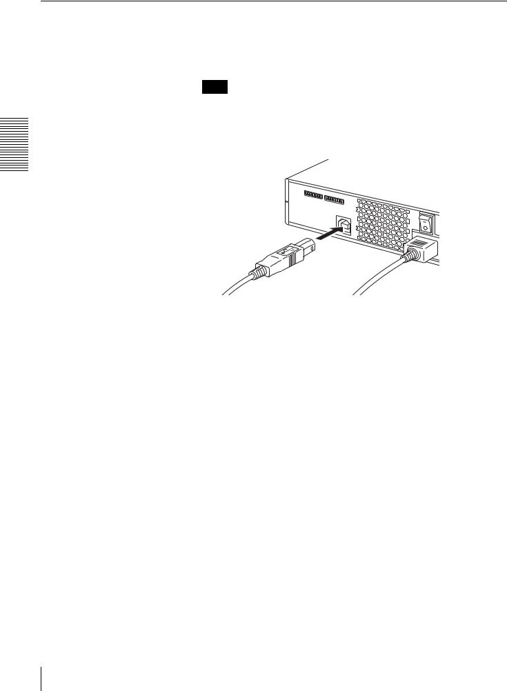
Connecting the BW-RU101
Started Getting 2 Chapter
Connect the unit to the host computer through a USB cable. You can use a USB Hub to connect up to 127 USB devices. Because BW-RU101 supports hot-plug, you can plug in, use, and unplug BW-RU101 without having to shut down the host computer.
Note
Before connecting the unit, make sure that it is off.
1 Connect the USB cable to the USB connector of the unit.
2 Connect the AC power cord to the AC IN connector of the unit.
USB Cables
To achieve high transfer rate and stable operations, the length of the USB cables should not exceed 5m.
Even though BW-RU101 is a hot-plug device, data may be lost when unplug the
USB cable, so confirm the following items before unplug the USB cable.
•Data saved to the disc is not accessed from an application or software.
•The BUSY indicator is off or lit green.
•The disc has been ejected. (Turning the unit off after ejecting the disc is recommended.)
14 Connecting the Unit
Setting Functions/SCSI ID
BW-RS101 Function Settings
Use the function switches A to P on the rear panel of the unit to set the unit’s functions and SCSI ID according to the host computer and software that you are using. Make sure that the unit is off before setting the switches.
|
|
|
A B C D F F G H |
I J K L M N O P |
|||||||||||||||||||||||||||||||||||||
|
I |
|
|
|
|
|
|
|
|
|
|
|
|
|
|
|
|
|
|
|
|
|
|
|
|
|
|
|
|
|
|
|
|
|
|
|
|
|
|
|
|
|
|
|
|
|
|
|
|
|
|
|
|
|
|
|
|
|
|
|
|
|
|
|
|
|
|
|
|
|
|
|
|
|
|
|
|
|
|
|
|
|
|
|
|
|
|
|
|
|
|
|
|
|
|
|
|
|
|
|
|
|
|
|
|
|
|
|
|
||||||||||||||||
|
O |
|
|
|
|
|
|
|
|
|
|
|
|
|
|
|
|
|
|
|
|
|
|
|
|
|
|
|
|
|
|
|
|
|
|
|
|
|
|
|
|
|
|
|
|
|
|
|
|
|
|
|
|
|
|
|
|
|
|
|
|
|
|
|
|
|
|
|
|
|
|
|
|
|
|
|
|
|
|
|
|
|
|
|
|
|
|
|
|
|
|
|
|
|
|
|
|
|
|
|
|
|
|
|
|
|
|
|
|
|
|
|
|
|
|
|
|
|
|
|
|
|
|
|
|
Switch |
|
|
|
Function |
|
|
|
|
1 |
|
|
|
|
|
|
|
|
|
|
0 |
|||||||||||||||||||||
A |
Terminator Power |
Supply POWER to the |
|
|
Supply POWER to the |
||||||||||||||||||||||||||||||||||||
|
|
|
|
|
|
|
|
|
|
|
|
|
|
|
|
|
|
terminator enabled |
|
|
terminator disabled |
||||||||||||||||||||
B |
Force CAV |
All operations are |
|
|
Optimum mode |
||||||||||||||||||||||||||||||||||||
|
|
|
|
|
|
|
|
|
|
|
|
|
|
|
|
|
|
performed in CAV |
|
|
enabled. (Automatic |
||||||||||||||||||||
|
|
|
|
|
|
|
|
|
|
|
|
|
|
|
|
|
|
seek mode. |
|
|
CAV/CLV selection) |
||||||||||||||||||||
C |
Background format |
Background Format |
|
|
Background Format |
||||||||||||||||||||||||||||||||||||
|
control |
mode enabled |
|
|
mode disabled |
||||||||||||||||||||||||||||||||||||
D |
Reserved* |
|
|
|
|
|
|
|
|
|
|
|
|
|
|
|
— |
||||||||||||||||||||||||
|
|
|
|
|
|
|
|
|
|
|
|
|
|
|
|
|
|
|
|
|
|
|
|
|
|
|
|
|
|
|
|
|
|||||||||
E |
Reserved* |
|
|
|
|
|
|
|
|
|
|
|
|
|
|
|
|||||||||||||||||||||||||
|
|
|
|
|
|
|
|
|
|
|
|
|
|
|
|
|
|
|
|
|
|
|
|
||||||||||||||||||
|
|
|
|
|
|
|
|
|
|
|
|
|
|
|
|
|
|
|
|
|
|
|
|
|
|
|
|
|
|
|
|
|
|
|
|
|
|
|
|
|
|
F |
Inhibit Verify |
Do not verify writes |
|
|
Verify write operations |
||||||||||||||||||||||||||||||||||||
G |
Write Cache control |
Write caching disabled |
Write caching enabled |
||||||||||||||||||||||||||||||||||||||
H |
Device Type |
Report 00H as device |
|
|
Report 07H as device |
||||||||||||||||||||||||||||||||||||
|
|
|
|
|
|
|
|
|
|
|
|
|
|
|
|
|
|
type (Direct Access |
|
|
type (Optical Memory |
||||||||||||||||||||
|
|
|
|
|
|
|
|
|
|
|
|
|
|
|
|
|
|
device) |
|
|
|
|
|
|
|
|
|
|
|
|
|
device) |
|||||||||
I |
SCSI Parity Check |
SCSI parity check |
|
|
SCSI parity check |
||||||||||||||||||||||||||||||||||||
|
|
|
|
|
|
|
|
|
|
|
|
|
|
|
|
|
|
enabled |
|
|
|
|
|
|
|
|
|
|
|
|
|
disabled |
|||||||||
J |
Reserved* |
|
|
|
|
|
|
|
|
|
|
|
|
|
|
|
|
|
|
|
|
|
|
|
|
||||||||||||||||
|
|
|
|
|
|
|
|
|
|
|
|
|
|
|
|
|
|
|
|
|
|
|
|
|
|
|
|
|
|
|
|
|
|
|
|
|
|
|
|
|
|
K |
Reserved* |
|
|
|
|
|
|
|
|
|
|
|
|
|
|
|
— |
||||||||||||||||||||||||
|
|
|
|
|
|
|
|
|
|
|
|
|
|
|
|
|
|
|
|
|
|
|
|
|
|
|
|
|
|
|
|
|
|
|
|
|
|
|
|
|
|
L |
Reserved* |
|
|
|
|
|
|
|
|
|
|
|
|
|
|
|
|
|
|
|
|
|
|
|
|
||||||||||||||||
|
|
|
|
|
|
|
|
|
|
|
|
|
|
|
|
|
|
|
|
|
|
|
|
|
|
|
|
|
|
|
|
|
|
|
|
|
|
|
|
|
|
M |
SCSI ID 3 |
To set the SCSI ID, see “BW-RS101 SCSI ID |
|||||||||||||||||||||||||||||||||||||||
|
|
|
|
|
|
|
|
|
|
|
|
|
|
|
|
|
|
Settings” on page 17. |
|
|
|
|
|
|
|
|
|
||||||||||||||
N |
SCSI ID 2 |
|
|
|
|
|
|
|
|
|
|||||||||||||||||||||||||||||||
|
|
|
|
|
|
|
|
|
|
|
|
|
|
|
|
|
|
|
|
|
|
|
|
||||||||||||||||||
|
|
|
|
|
|
|
|
|
|
|
|
|
|
|
|
|
|
|
|
|
|
|
|
|
|
|
|
|
|
|
|
|
|
|
|
|
|
|
|
|
|
O |
SCSI ID 1 |
|
|
|
|
|
|
|
|
|
|
|
|
|
|
|
|
|
|
|
|
|
|
|
|
||||||||||||||||
|
|
|
|
|
|
|
|
|
|
|
|
|
|
|
|
|
|
|
|
|
|
|
|
|
|
|
|
|
|
|
|
|
|
|
|
|
|
|
|
|
|
P |
SCSI ID 0 |
|
|
|
|
|
|
|
|
|
|
|
|
|
|
|
|
|
|
|
|
|
|
|
|
||||||||||||||||
|
|
|
|
|
|
|
|
|
|
|
|
|
|
|
|
|
|
|
|
|
|
|
|
|
|
|
|
|
|
|
|
|
|
|
|
|
|
|
|
|
|
|
|
|
|
|
|
|
|
|
|
|
|
|
|
|
|
|
|
|
|
|
|
|
|
|
|
|
|
|
|
|
|
|
|
|
|
|
|
|
:Factory Settings |
||
|
|
|
|
|
|
|
|
|
|
|
|
|
|
|
|
|
|
|
|
|
|
|
|
|
|
|
|
|
|
|
|
|
|
|
|
|
|
|
|||
|
|
|
|
|
|
|
|
BW-RS101 Function switch settings |
|||||||||||||||||||||||||||||||||
Note
•Reserved*
Do not set any of the reserved switches to 1, changing the reserved switches setting may cause the unit failure.
Started Getting 2 Chapter
Setting Functions/SCSI ID |
15 |
|
|

Started Getting 2 Chapter
16 Setting Functions/SCSI ID
•Background Formatting
This unit is equipped with a background formatting function. To improve the reliability of writing data, executing a physical format before using an unused disc is highly recommended. If you disable the background formatting function, you can start the physical format in the foreground by issuing the FORMAT command. During the format, the unit scans whole sectors of the disc to detect any defect sectors and register them as defective sectors. It takes around 80 minutes to complete. If you enable the background formatting function, the unit starts the physical format automatically in the background without having to receive the FORMAT command. Therefore, you can even read and write data during the format. It takes at least 135 minutes to complete.
Cautions
•Background Formatting Precautions
Never turn off the unit without making sure that the disc is removed when the disc is in the background formatting process. The unit may not write data properly and mark them as the defective sectors if you turn off the unit without ejecting the disc during the background formatting. Before turning off the unit, be sure to eject the disc using the EJECT command or pressing the eject button.
•Inhibit Verify
Using a physical formatted disc is highly recommended if you inhibit verify for writes. Although disable verify for writes quicken the write transfer rate, but may reduce the reliability of written data. Even if you inhibit verify for writes, if the disc is not physical formatted, the drive forces verify for all write operations.
•Write Cache Precautions
This unit is equipped with a write cache function. When the write cache is enabled, never turn off the unit power without making sure that all data has been written to the disc from the cache memory. Data will be lost if you turn off the power before all data in cache memory has been written to the disc.
Before turning off the unit power, be sure to eject the disc, as this writes data from cache memory to the disc. Further, even though the unit will periodically flush data from cache memory periodically to the disc, data may be lost in the case of a power failure.

BW-RS101 SCSI ID Settings
Use function switches M to P to set the SCSI ID.
SCSI ID |
|
Function switch |
|
|
|
|
|
|
|
|
P (SCSI 0) |
O (SCSI 1) |
N (SCSI 2) |
M (SCSI 3) |
|
|
|
|
|
0 |
OFF |
OFF |
OFF |
OFF |
|
|
|
|
|
1 |
ON |
OFF |
OFF |
OFF |
|
|
|
|
|
2 |
OFF |
ON |
OFF |
OFF |
|
|
|
|
|
3 |
ON |
ON |
OFF |
OFF |
|
|
|
|
|
4 |
OFF |
OFF |
ON |
OFF |
|
|
|
|
|
5 |
ON |
OFF |
ON |
OFF |
|
|
|
|
|
6 |
OFF |
ON |
ON |
OFF |
|
|
|
|
|
7 |
ON |
ON |
ON |
OFF |
|
|
|
|
|
8 |
OFF |
OFF |
OFF |
ON |
|
|
|
|
|
9 |
ON |
OFF |
OFF |
ON |
|
|
|
|
|
10 |
OFF |
ON |
OFF |
ON |
|
|
|
|
|
11 |
ON |
ON |
OFF |
ON |
|
|
|
|
|
12 |
OFF |
OFF |
ON |
ON |
|
|
|
|
|
13 |
ON |
OFF |
ON |
ON |
|
|
|
|
|
14 |
OFF |
ON |
ON |
ON |
|
|
|
|
|
15 |
ON |
ON |
ON |
ON |
|
|
|
|
|
SCSI ID settings
Started Getting 2 Chapter
Note
Make sure to select a SCSI ID that has not been assigned to another SCSI device.
Setting Functions/SCSI ID |
17 |
|
|
BW-RU101 Function Settings
Started Getting 2 Chapter
Use function switches B to H on the rear panel of the unit to select the unit's functions according to the host computer and software that you are using. Make sure that the unit is off before setting the switches.
|
|
|
A B C D F F G H |
I J K L M N O P |
||||||||||||
|
I |
|
|
|
|
|
|
|
|
|
|
|
|
|
|
|
|
|
|
|
|
|
|
|
|
|
|
|
|
|
|
|
|
|
|
|
|
|
|
|
|
|
|
|
|
|
|
|
||
|
O |
|
|
|
|
|
|
|
|
|
|
|
|
|
|
|
|
|
|
|
|
|
|
|
|
|
|
|
|
|
|
|
|
|
|
|
|
|
|
|
|
|
|
|
|
|
|
|
|
|
Switch |
|
|
Function |
|
|
|
|
|
1 |
|
0 |
|||||
A |
Reserved |
|
|
|
|
|
|
— |
||||||||
|
|
|
|
|
|
|
|
|
|
|
|
|
|
|
|
|
B |
Force CAV |
All operations are |
|
Optimum mode |
||||||||||||
|
|
|
|
performed in CAV |
|
enabled. (Automatic |
||||||||||
|
|
|
|
seek mode. |
|
CAV/CLV selection) |
||||||||||
C |
Background format |
Background Format |
|
Background Format |
||||||||||||
|
control |
mode enabled |
|
mode disabled |
||||||||||||
D |
Reserved* |
|
|
|
|
|
|
— |
||||||||
|
|
|
|
|
|
|
|
|
|
|||||||
E |
Reserved* |
|
|
|
|
|
|
|||||||||
|
|
|
|
|
|
|
|
|
|
|
|
|
||||
|
|
|
|
|
|
|
|
|
|
|
|
|
|
|
|
|
F |
Inhibit Verify |
Do not verify writes |
|
Verify write operations |
||||||||||||
G |
Write Cache control |
Write caching disabled |
Write caching enabled |
|||||||||||||
H |
Device Type |
Report 00H as device |
|
Report 07H as device |
||||||||||||
|
|
|
|
type (Direct Access |
|
type (Optical Memory |
||||||||||
|
|
|
|
device) |
|
|
device) |
|||||||||
I |
Reserved* |
|
|
|
|
|
|
|
|
|
|
|
|
|
||
|
|
|
|
|
|
|
|
|
|
|
|
|
|
|
|
|
J |
Reserved* |
|
|
|
|
|
|
|
|
|
|
|
|
|
||
|
|
|
|
|
|
|
|
|
|
|
|
|
|
|
|
|
K |
Reserved* |
|
|
|
|
|
|
|
|
|
|
|
|
|
||
|
|
|
|
|
|
|
|
|
|
|
|
|
|
|
|
|
L |
Reserved* |
|
|
|
|
|
|
— |
||||||||
|
|
|
|
|
|
|
|
|
|
|||||||
M |
Reserved* |
|
|
|
|
|
|
|||||||||
|
|
|
|
|
|
|
|
|
|
|
|
|
||||
|
|
|
|
|
|
|
|
|
|
|
|
|
|
|
|
|
N |
Reserved* |
|
|
|
|
|
|
|
|
|
|
|
|
|
||
|
|
|
|
|
|
|
|
|
|
|
|
|
|
|
|
|
O |
Reserved* |
|
|
|
|
|
|
|
|
|
|
|
|
|
||
|
|
|
|
|
|
|
|
|
|
|
|
|
|
|
|
|
P |
Reserved* |
|
|
|
|
|
|
|
|
|
|
|
|
|
||
|
|
|
|
|
|
|
|
|
|
|
|
|
|
|
|
|
|
|
|
|
|
|
|
|
|
|
|
|
|
:Factory Settings |
|||
|
|
|
|
|
|
|
|
|
|
|
|
|
||||
|
|
|
BW-RU101 Function switch settings |
|||||||||||||
Note
•Reserved*
Do not set any of the reserved switches to 1, changing the reserved switches setting may cause the unit failure.
18 Setting Functions/SCSI ID

•Background Formatting
This unit is equipped with a background formatting function. To improve the reliability of writing data, executing a physical format before using an unused disc is highly recommended. If you disable the background formatting function, you can start the physical format in the foreground by issuing the FORMAT command. During the format, the unit scans whole sectors of the disc to detect any defect sectors and register them as defective sectors. It takes around 80 minutes to complete. If you enable the background formatting
function, the unit starts the physical format automatically in the background without having to receive the FORMAT command. Therefore, you can even read and write data during the format. It takes at least 135 minutes to complete.
Cautions
•Background Formatting Precautions
Never turn off the unit without making sure that the disc is removed when the disc is in the background formatting process. The unit may not write data properly and mark them as the defective sectors if you turn off the unit without ejecting the disc during the background formatting. Before turning off the unit, be sure to eject the disc using the EJECT command or pressing the eject button.
•Inhibit Verify
Using a physical formatted disc is highly recommended if you inhibit verify for writes. Although disable verify for writes quicken the write transfer rate, but may reduce the reliability of written data. Even if you inhibit verify for writes, if the disc is not physical formatted, the drive forces verify for all write operations.
•Write Cache Precautions
This unit is equipped with a write cache function. When the write cache is enabled, never turn off the unit power without making sure that all data has been written to the disc from the cache memory. Data will be lost if you turn off the power before all data in cache memory has been written to the disc.
Before turning off the unit power, be sure to eject the disc, as this writes data from cache memory to the disc. Further, even though the unit will periodically flush data from cache memory periodically to the disc, data may be lost in the case of a power failure.
Setting Functions/SCSI ID
Started Getting 2 Chapter
19
Using Discs
Inserting a Disc
Started Getting 2 Chapter
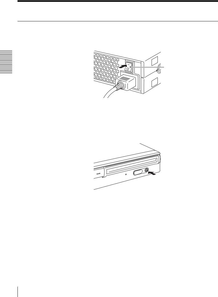
1 Turn on the unit.
Press the power switch on the rear panel of the unit.
Press this mark on the power switch.
2 Start the host computer.
Refer to the documentation of the host computer for details.
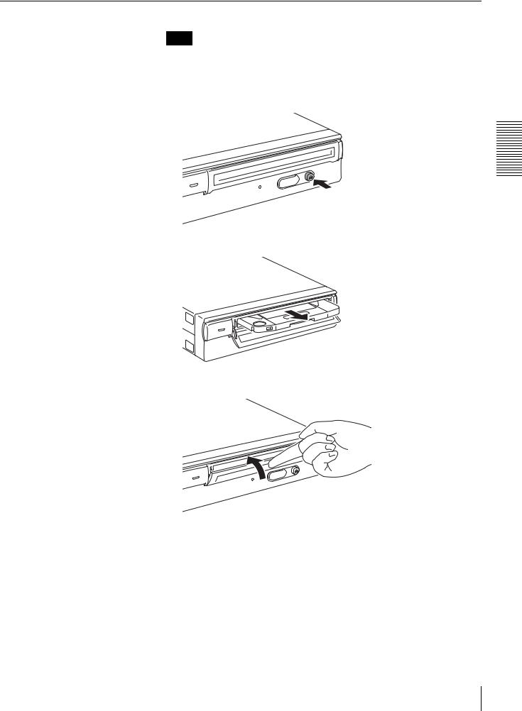
3 Open the slot cover.
Automatic opening
Press the eject button to open the slot cover.
20 Using Discs
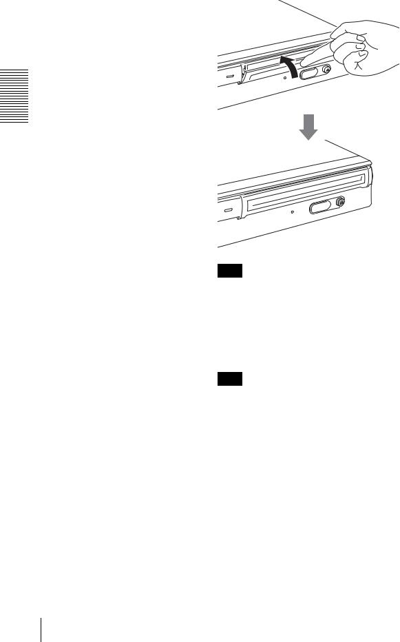
Manual opening
Open the slot cover by pulling it toward you as illustrated.
Started Getting 2 Chapter
Note
Gently open the slot cover without applying any excessive force.
4 Insert a disc.
Insert the disc in the direction illustrated.
Note
Inserting the disc in the wrong direction may damage the disc and/or unit.
More than 15°
Using Discs 21
Started Getting 2 Chapter
5 Close the slot cover.
After confirm the disc is loaded completely, close the slot cover with your finger.
Note
To prevent dust from entering the unit, be sure to keep the slot cover closed when not inserting or ejecting a disc.
6 Read and/or write data on the disc.
Use SCSI commands or software on the host computer to read and/or write data on the disc. The BUSY indicator lit amber except when data is being read/written.
Note
For details, refer to the “Professional Disc for DATA” installation guide available on the Sony Web site at http://www.sony.net/ProDATA/.
22 Using Discs
Ejecting a Disc
Note
Even after data write on the host computer has finished, the BUSY indicator may lit amber to indicate data is being written to the drive. In this case, do not press the eject button.
1 Eject the disc with the EJECT command or by pressing the eject button.
The unit automatically opens the slot cover when ejecting the disc.
Started Getting 2 Chapter
2 Close the slot cover with your finger after removing the disc from the unit.
Using Discs 23
Started Getting 2 Chapter
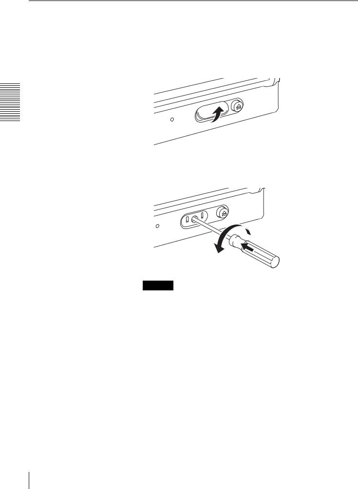
What to Do when You Cannot Eject a Disc
Emergency Eject Hole
If you cannot eject the disc with the eject button or EJECT command, turn off the unit and then use a Phillips precision screwdriver in the emergency-eject hole to eject the disc.
1 Remove the emergency eject hole cover.
2 Insert the Phillips precision screwdriver (diameter of 5 mm) into the emergency-eject hole and turn it counterclockwise while pushing it forward. (You need to turn the driver about 200 times to eject the disc.)
Caution
If the driver becomes difficult to turn, do not use excessive force. Doing so may damage the unit and/or the disc. If the disc cannot be ejected after performing above contact your dealer.
24 Using Discs
About Handling Discs
How to Protect Disc Data
•Do not drop the disc cartridge or subject it to any violent shocks or vibrations.
•Do not disassemble the disc cartridge. It is a precision component that was carefully adjusted prior to shipment.
•Do not open the disc cartridge shutter manually or touch the disc inside. The shutter is designed to open automatically when the disc cartridge is inserted into the devices.
•Do not use the disc cartridge under high humidity and/or wide temperature fluctuation ambient conditions. Condensation may make it impossible to read or write data.
•Store the disc cartridge in its hard case.
•Do not expose the disc cartridge to direct sunlight or excessive heat, such as on the dashboard or glove compartment of an automobile.
•Do not store the disc cartridge under the following conditions:
-Location exposed to excessive dust and/or debris.
-Location exposed to direct sunlight.
-Near heat sources.
-Location subject to high humidity.
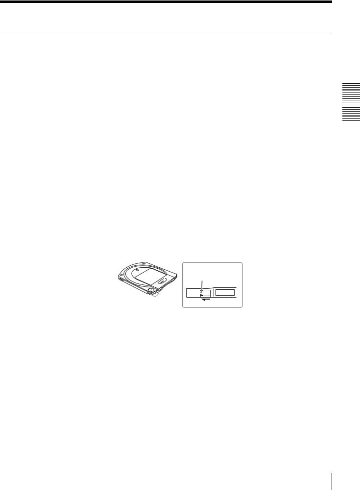
Write-protect switch
Data cartridges are equipped with a write-protect switch to prevent the accidental deletion of data on the disc cartridge or the inadvertent writing of unwanted data.
Slide the switch in the direction of the arrow as illustrated below. A red surface appears in place of the switch to indicate that the cartridge is write-protected. To release the protection, return the switch to its original position.
Write-protect switch
Refer to the description of the disc.
Cleaning discs
The disc cartridge is designed to guard against dust and other airborne containments. Therefore there is no need to clean the discs. Using a disc cleaning device may damage the surface of the disc.
What to do when a disc is locked
To avoid locking the disc, do not insert it into the unit when the unit is off. If the disc is locked, turn on the unit, confirm that the disc is completely loaded into the unit, and then eject the disc by issuing the EJECT command or pressing the eject button.
Started Getting 2 Chapter
About Handling Discs 25

Usage Precautions Chapter
Unit Usage Precautions
Power Supply
•Be sure to use 100 to 240 V AC.
•Do not share the AC outlet with any other power-consuming equipment such as copying machines or shredders.
Handling the Power Cable
•Take care not to place or drop anything heavy on the power cable or to damage the cable. Using a damaged cable is dangerous.
•Be sure to hold the plug when disconnecting the power cable from the outlet. Pulling the cable may damage the cable.
•When the unit is not to be used for a long time, disconnect the power cable from the outlet.
Location
The unit must be placed horizontally or vertically on a flat, stable surface. The maximum permissible mounting tilt is 10° for the bottom placed surface.
Location requirements
Careful consideration should be given to the following in selecting a site to install or store your unit.
Avoid the following conditions:
•High humidity
•High temperatures
•Direct sunlight
•Dust
•Strong vibration
•Wide temperature fluctuations
Do not subject the unit to shock or vibration
Dropping the unit or subjecting it to strong impact may damage the unit.
26 Unit Usage Precautions

Ventilation
Care should be exercised to prevent the internal mechanisms of the unit from overheating. Be careful not to clog or block the vent, or place the unit in an area with poor ventilation. The unit may stop operating altogether if the internal temperature becomes too high.
Moving the unit
Be sure to remove the disc cartridge when the unit is not being used. Also never move or transport the unit with the disc cartridge still inserted.
While in operation, the disc rotates at a high speed. Moving the unit at such a time may disturb the spinning disc and cause it to be damaged. Always remove the disc cartridge before moving your unit.
Condensation
Avoid subjecting the unit to extremes in temperature. If, for example, the unit is moved suddenly from a very cold location to a warm one, moisture from condensation may form within the unit due to the quick rise in ambient temperature. If a sudden change in the temperature cannot be avoided, wait for an hour or more before using the unit. Inserting a disc cartridge into the mechanism when moisture is present may cause damage to both the disc and the unit. Remove the disc cartridge immediately if you suspect any condensation problems. The moisture should evaporate quickly if the unit is left on without a disc inserted.
Temperature Alarm
When the temperature in the unit exceeds the preset level, the BUSY indicator starts flashing on and off at about 2-seconds intervals, regardless of whether or not a disc is being accessed, and the unit stops operating. If this happens, you should improve the ventilation of a setting area.
If the unit still refuses to operate, unplug the unit and contact your dealer.
Cleaning the Unit
Do not use a lens cleaning devices.
The internal lens cleaning brush mechanism ensures periodic, automatic cleaning of the pickup lens. Therefore thee is no need to clean the lens of the unit. Using a lens cleaning devices may damage the lens.
Make sure cleaning products are not used to clean a disc or the lens of the unit.
Maintenance
Clean the cabinet with a dry soft cloth, or with a soft cloth lightly moistened with a mild detergent solution. Do not use any type of solvent, such as alcohol or benzine, which may damage the finish.
If problems occur
If any problems occur, turn off the power and unplug the unit, contact your dealer.
Precautions Usage 3 Chapter
Unit Usage Precautions |
27 |
|
|

Specifications Chapter
Specifications
Note
Specifications are subject to change without notice.
Disc Specifications
The BW-RS101 and BW-RU101 are compatible with two types of disc.
Capacity of the data zone |
23.3 GB/disc (2048 bytes/sector) |
|
|
User data transfer rate |
|
|
|
Sustained write |
9 MB/s (CLV) |
|
|
|
4.5 to 9.0 MB/s (CAV) |
|
|
Sustained read |
10.8 MB/s (CLV) |
|
|
|
4.5 to 10.8 MB/s (CAV) |
|
|
Specifications
Performance
Disc rotation speed
CLV sustained read (inner) |
5042 min–1 (rpm) |
CLV sustained read (outer) |
2086 min–1 (rpm) |
CLV sustained write (inner) |
4201 min–1 (rpm) |
CLV sustained write (outer) |
1738 min–1 (rpm) |
CAV sustained read/write |
2100 min–1 (rpm) |
Seek time |
|
|
|
1/3 stroke |
320 ms (CLV sustained write) |
|
|
|
110 ms (CAV) |
|
|
Full stroke |
900 ms (CLV sustained write) |
|
|
|
200 ms (CAV) |
|
|
28 Specifications

Controller Block Specifications
Host interface
BW-RS101 |
Ultra 160 LVD/SE SCSI SCSI parallel |
|
interface-3 (SPI-3) [ANSI NCITS.336:2000] |
|
|
BW-RU101 |
Hi-Speed USB(USB 2.0) |
|
|
Burst data transfer rate |
|
|
|
BW-RS101 |
160 MB/s synchronous (maximum) |
|
|
BW-RU101 |
480 Mbps (maximum) |
|
|
Buffer memory capacity |
16 MB |
|
|
Laser Diode Specifications
Type |
Semiconductor laser (GaN) |
|
|
Output power |
35 mW (CW), 65 mW (pulse) |
|
|
Wavelength |
403 to 410 nm |
|
|
Environmental Specifications
Operating temperature |
+5 to +40°C (+41 to +104°F) |
|
|
Storage temperature |
–30 to +60°C (–22 to +140°F) |
|
|
Maximum temperature |
+10°C/h (+18°F/h) |
gradient |
|
|
|
Operating humidity |
+10% to +90% RH, non-condensing |
|
|
Storage humidity |
+5% to +90% RH, non-condensing |
|
|
Mounting orientation |
Horizontal or vertical |
|
|
Mounting tilt |
Less than ±10° |
|
|
Mechanical Specifications
Power supply |
100-240 V AC, 50/60 Hz |
|
|
Current consumption |
0.35-0.50 A (maximum) |
|
|
Dimensions (W × H × D) |
199 × 59 × 306 mm (7.8 × 2.3 × 12.1 in.) |
|
(approximately) |
|
|
Mass |
4.0 kg (8.8 lb.) (approximately) |
|
|
Specifications 4 Chapter
Specifications 29

Règlements de sécurité
Précaution
La prise secteur de cet appareil doit être utilisée pour débrancher l’alimentation secteur. S’assurer que les prises sont installées à proximité de l’équipement et qu’elles sont facilement accessibles.
Traitement des appareils électriques et électroniques en fin de vie (Applicable dans les pays de l’Union Européenne et aux autres pays européens disposant de systèmes de collecte sélective)
Ce symbole, apposé sur le produit ou sur son emballage, indique que ce produit ne doit pas être traité avec les déchets ménagers. Il doit
être remis à un point de collecte approprié
 pour le recyclage des équipements électriques et électroniques. En s’assurant que ce produit est bien mis au rebus de manière appropriée, vous aiderez
à prévenir les conséquences négatives potentielles pour l’environnement et la santé humaine. Le recyclage des matériaux aidera à conserver les ressources naturelles. Pour toute information supplémentaire au sujet du recyclage de ce produit, vous pouvez contacter votre municipalité, votre déchetterie ou le magasin où vous avez acheté le produit.


 et « Professional Disc for DATA » sont des marques commerciales de Sony Corporation.
•Le fabricant décline toute responsabilité pour les pertes subies suite au mauvais fonctionnement ou à l’utilisation de ce produit.
•Le fabricant ne garantit pas la sécurité des données enregistrées en utilisant ce produit. Pour éviter toute perte accidentelle de données, une copie de sauvegarde fréquente est fortement recommandée.
•La reproduction du contenu de ce mode d’emploi, en totalité ou en partie, est interdite.
2
 Loading...