


 Loading...
3-854-212-17 (1)
3CCD Color
Video Camera
Operating Instructions
BRC-300/300P
© 2004 Sony Corporation

Owner’s Record
The model and serial numbers are located on the bottom. Record these numbers in the spaces provided below. Refer to these numbers whenever you call upon your Sony dealer regarding this product.
Model No.
Serial No.
WARNING
To reduce a risk of fire or electric shock, do not expose this product to rain or moisture.
To avoid electrical shock, do not open the cabinet. Refer servicing to qualified personnel only.
WARNING
Use the Sony MPA-AC1 AC power adapter provided with this equipment as a power supply source. Any other power sources may result in hazards such as a fire. This product has no power switch.
Disconnect device of this equipment is the mains plug of the AC adapter.
The mains plug on this equipment must be used to disconnect mains power.
Please ensure that the socket outlet is installed near the equipment and shall be easily accessible.
In the event of abnormal operations, disconnect the mains plug.
WARNING (For Installers only)
Instruction for installing the equipment on the ceiling: After the installation, ensure the connection is capable of supporting four times the weight of the equipment downwards.
IMPORTANT
Nameplate is located on the bottom.
ATTENTION
The electromagnetic fields at the specific frequencies may influence the picture of this unit.
For customers in the U.S.A.
This device complies with Part 15 of the FCC Rules. Operation is subject to the following two conditions:
(1) This device may not cause harmful interference, and (2) this device must accept any interference received, including interference that may cause undesired operation.
This equipment has been tested and found to comply with the limits for a Class A digital device, pursuant to Part 15 of the FCC Rules. These limits are designed to
provide reasonable protection against harmful interference when the equipment is operated in a commercial environment. This equipment generates, uses, and can radiate radio frequency energy and, if not installed and used in accordance with the instruction manual, may cause harmful interference to radio communications. Operation of this equipment in a residential area is likely to cause harmful interference in which case the user will be required to correct the interference at his own expense.
You are cautioned that any changes or modifications not expressly approved in this manual could void your authority to operate this equipment.
The shielded interface cable recommended in this manual must be used with this equipment in order to comply with the limits for a computing device pursuant to Subpart B of Part 15 of FCC Rules.
For the customers in Canada
This Class A digital apparatus complies with Canadian ICES-003.
Pour les utilisateurs au Canada
Cet appareil numérique de la classe A est conforme à la norme NMB-003 du Canada.
For the customers in Europe
Warning
This is a Class A product. In a domestic environment, this product may cause radio interference in which case the user may be required to take adequate measures. In the case that interference should occur, consult your nearest authorized Sony service facility.
INTERFACE CABLE
This device requires shielded interface cables to comply with FCC emission limits.
Notice for CCFC-M100 Optical Fiber Cable
Only trained and qualified personnel should be allowed to install this equipment with the cable.
WARNING :
The cable is rated flammability class VW-1 and may be for indoor use only in some countries. Use appropriate alternative cables in accordance with the regulations and laws for each country taking the application and environment into account.
2

Table of Contents |
|
Getting Started |
|
Precautions ............................................................. |
5 |
Typical CCD Phenomena ...................................... |
5 |
Overview |
|
Features .................................................................. |
6 |
System Components .............................................. |
7 |
Supplied Components and Accessories .............. |
7 |
Optional Products ............................................... |
8 |
System Configuration .......................................... |
10 |
Operating a BRC-300/300P Camera Using the |
|
Supplied Remote Commander ....................... |
10 |
Operating a BRC-300/300P Camera Using the |
|
RM-BR300 Remote Control Unit .................. |
10 |
Operating Multiple BRC-300/300P Cameras Us- |
|
ing the RM-BR300 Remote Control Unit ...... |
11 |
Operating a BRC-300/300P Camera from a Long |
|
Distance .......................................................... |
12 |
Operating Multiple BRC-300/300P Cameras from |
|
a Long Distance .............................................. |
13 |
Using BRC-300/300P Cameras and VISCA-con- |
|
trollable Cameras in the Same System ........... |
14 |
Location and Function of Parts .......................... |
15 |
Camera ............................................................. |
15 |
Remote Commander (supplied) ....................... |
17 |
RM-BR300 Remote Control Unit |
|
(not supplied) ................................................. |
18 |
BRU-300/300P Optical Multiplex Unit (not |
|
supplied) ......................................................... |
21 |
BRBK-301 Analog RGB Component Card |
|
(not supplied) ................................................. |
22 |
BRBK-302 SDI Card (not supplied) ................ |
22 |
BRBK-303 Optical Multiplex Card |
|
(not supplied) ................................................. |
22 |
Adjusting and Setting With Menus |
|
About On-Screen Menus ..................................... |
23 |
Main Menu ........................................................ |
23 |
Setting Menus ................................................... |
23 |
Operation Through Menus ................................. |
24 |
Menu Operation Using the Supplied Remote |
|
Commander ..................................................... |
24 |
Menu Operation Using the RM-BR300 Remote |
|
Control Unit .................................................... |
25 |
EXPOSURE Menu ............................................... |
26 |
FOCUS Menu ....................................................... |
27 |
WHITE BALANCE Menu .................................. |
27 |
PAN TILT ZOOM Menu ..................................... |
28 |
PICTURE Menu ................................................... |
29 |
SYSTEM Menu .................................................... |
29 |
ANALOG OUT Menu ......................................... |
30 |
Operation Using the Supplied |
|
Remote Commander |
|
Turning on the Power .......................................... |
31 |
Pan/Tilt and Zoom Operation ............................. |
31 |
Panning and Tilting ........................................... |
31 |
Zooming ............................................................ |
32 |
Operating Multiple Cameras with the Remote |
|
Commander ..................................................... |
32 |
Adjusting the Camera .......................................... |
33 |
Focusing on a Subject ....................................... |
33 |
Shooting with Back Lighting ............................ |
33 |
Storing the Camera Settings in Memory |
|
– Presetting Feature ............................................. |
34 |
Operation Using the RM-BR300 |
|
Remote Control Unit |
|
Turning on the Power .......................................... |
35 |
Operating Multiple Cameras ............................. |
35 |
Pan/Tilt and Zoom Operation ............................. |
36 |
Panning and Tilting ........................................... |
36 |
Zooming ............................................................ |
37 |
Adjusting the Camera .......................................... |
38 |
Focusing on a Subject ....................................... |
38 |
Shooting with Back Lighting ............................ |
38 |
Adjusting the White Balance ............................ |
38 |
Adjusting the Brightness ................................... |
39 |
Storing the Camera Settings in Memory |
|
– Presetting Feature ............................................. |
40 |
Table of Contents |
3 |
|
|

Installation and Connections |
|
Installation ........................................................... |
42 |
Attaching an Interface Card ............................. |
42 |
Installing the Camera ....................................... |
42 |
Installing the Camera on the Ceiling ................ |
43 |
Connections .......................................................... |
46 |
Connecting to an AC Outlet ............................. |
46 |
Connecting the RM-BR300 Remote Control Unit |
|
......................................................................... |
47 |
Connecting a Video Monitor, VTR, etc. Equipped |
|
with the Composite Video Input Connector ... |
48 |
Connecting a Video Monitor, VTR, etc. Equipped |
|
with the S-Video Input Connector ................. |
48 |
Connecting a Device Equipped with VISCA RS- |
|
232C Connector ............................................. |
49 |
Connecting a Device Equipped with VISCA RS- |
|
422 Connector ................................................ |
49 |
Connecting a Video Monitor Equipped with |
|
Analog RGB/Component Connectors ............ |
50 |
Connecting a VTR Equipped with SDI Input |
|
Connector ....................................................... |
51 |
Connecting the BRU-300/300P Optical Multiplex |
|
Unit ................................................................. |
51 |
Connecting a Video Switcher ........................... |
52 |
Connecting a Sync Signal Generator ............... |
53 |
Appendix |
|
List of Messages ................................................... |
54 |
Troubleshooting ................................................... |
55 |
Menu Configuration ............................................ |
57 |
Presetting Items ................................................... |
59 |
Specifications ....................................................... |
60 |
Dimensions ....................................................... |
61 |
Pin Assignments ............................................... |
64 |
Wiring Diagram of VISCA RS-422 Connection |
|
......................................................................... |
67 |
Using the VISCA RS-422 Connector Plug ...... |
68 |
4 Table of Contents
Getting Started
Precautions
Operating or storage location
Operating or storing the camera in the following locations may cause damage to the camera:
•Extremely hot or cold places (Operating temperature: 0°C to 40°C [32°F to 104°F])
•Exposed in direct sunlight for a long time, or close to heating equipment (e.g., near heaters)
•Close to sources of strong magnetism
•Close to sources of powerful electromagnetic radiation, such as radios or TV transmitters
•Locations subject to strong vibration or shock
Ventilation
To prevent heat buildup, do not block air circulation around the camera.
Transportation
When transporting the camera, repack it as originally packed at the factory or in materials equal in quality.
Cleaning
•Use a blower to remove dust from the lens or optical filter.
•Use a soft, dry cloth to clean the external surfaces of the camera. Stubborn stains can be removed using a soft cloth dampened with a small quantity of detergent solution, then wipe dry.
•Do not use volatile solvents such as alcohol, benzene or thinners as they may damage the surface finishes.
Maintenance
The camera mechanism may cause abnormal noise due to wear and lubrication loss after a long period of use. To maintain optimum performance, we recommend periodical maintenance. If abnormal noise occurs, consult with your Sony dealer.
Note on laser beams
Laser beams may damage a CCD. You are cautioned that the surface of a CCD should not be exposed to laser beam radiation in an environment where a laser beam device is used.
Typical CCD Phenomena
The following phenomena may appear on the monitor screen while you are using the BRC-300/300P color video camera. These phenomena stem from the high sensitivity of the CCD image sensors, and do not indicate a fault within the camera.
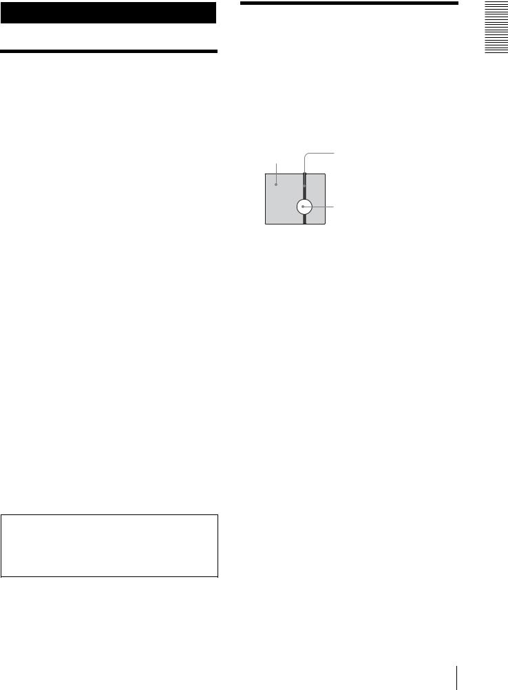
Vertical smear
A “smear” may appear to extend vertically from very bright subjects, as shown below.
Video monitor |
Pale vertical |
|
screen |
||
smear |
||
|
Very bright subject (such as an electric lamp, fluorescent lamp, sunlight, or strong reflected light)
This phenomenon is common to CCD imaging elements using an interline transfer system, and is caused when electric charge induced by infrared radiation deep within the photo sensor is transferred to the resistors.
Aliasing
When shooting fine stripes, straight lines or similar patterns, the lines may become slightly jagged.
Blemishes
A CCD image sensor consists of an array of individual picture elements (pixels). A malfunctioning sensor element will show up as a single pixel blemish in the image. This is generally not a problem.
White speckles
When you shoot a poorly illuminated object at a high temperature, small white dots may appear all over the entire screen image.
Started Getting
Precautions / Typical CCD Phenomena 5

Overview
Overview
Features
Compact, 3CCD video camera with builtin pan/tilt/zoom functions
•The camera integrates the 3CCD camera block, pan/ tilt mechanism, and 12-magnification optical zoom with 4-magnification digital zoom in a compact body. The compactness and integration allow the camera versatile usage.
•The camera is provided with a wide-angle pan/tilt mechanism of ±170º horizontally, 90º upward and 30º
downward, which enables wide-range remote shooting.
•The new pan/tilt mechanism enabling smooth camera movement even at low speed realizes a minimum pan/ tilt speed of 0.25º per second.
•The pan/tilt mechanism is remarkably quiet, even at the maximum pan/tilt speed of 60º per second.
Mega-pixel 3CCD camera allowing high image quality and high-resolution remote shooting
•The camera incorporates three 1/4.7 type Advanced HAD* CCDs containing 1,070,000 picture elements in total.
*HAD is an abbreviation of Hole-Accumulated Diode.
Advanced HAD is a trademark of Sony Corporation.
•The camera realizes the high-quality image and high resolution, having a minimum illumination of 7 lx, horizontal resolution of 600 TV lines, and signal-to- noise ratio of more than 50 dB. In addition, the use of a primary-color optical prism enables shooting with superior color reproduction.
•A fine image is obtained by employing a newlydeveloped DSP of 14-bit A/D conversion for signal processing. This also greatly reduces digital noise and is effective for shooting at low illumination and shooting of black subjects.
•The aspect ratio of the camera image is selectable between 4:3 or 16:9. In addition, an optional wide conversion lens can be attached to the camera, allowing use in various shooting conditions.
Built-in interface card slot
The camera is equipped with an interface card slot for the optional BRBK-301 Analog RGB Component Card, BRBK-302 SDI Card or BRBK-303 Optical Multiplex Card. Use of these interface cards gives the camera the capability of having various image output formats.
Long-distance image transmission and pan/tilt/zoom control
•Combined use of the BRBK-303 Optical Multiplex Card, CCFC-M100 Optical Fiber Cable and BRU300/300P Optical Multiplex Unit, and Sony's unique camera connection technology and optical digital multiplex transmission technology allows short to long distance (up to 500 m, or 1,640 feet) transmission of camera images and pan/tilt/zoom control signals. Use of the optical fiber cable enables an economical and easy system configuration for long distance.
•The supplied ceiling bracket allows installation of the camera on a ceiling.
VISCA camera protocol supported
•The camera is equipped with both RS-232C and RS422 communication interfaces. As the camera supports the industry-standard VISCA camera protocol, up to 7 cameras can be connected and remotely controlled at a high communication speed of 38,400 bps.
•The optional RM-BR300 Remote Control Unit allows easy camera operations.
•The VISCA protocol allows use of cameras and controllers of other manufacturers together with those of Sony.
External video sync function
The camera is equipped with an external video sync function to synchronize the camera images on multiple cameras. The camera also has a composite video output connector and S video output connector as standard equipment.
Tally lamp
The tally lamp of the camera allows you to make sure it is selected at a glance.
Mounted circuit board using lead-free solder
Lead-free solder is used for the circuit boards of the camera for environmental reasons.
6 Features

System Components
In order to support multiple system configurations, a variety of optional products are available for the BRC300/300P 3CCD Color Video Camera. This section introduces these optional products as well as the accessories supplied with the camera.
Supplied Components and
Accessories
Before using the camera, make sure you have the following components and accessories supplied.
Camera (1)
AC power adaptor MPA-AC1 (Sony) (1)
AC power cord (1)
USA and Canadian model
European model
Remote commander (1)
Two R6 (size AA) batteries are not supplied.
Ceiling bracket (A) (1)
Ceiling bracket (B) (1)
Wire rope (1)
Overview
System Components |
7 |
|
|
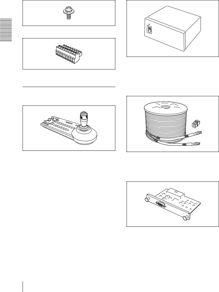
Screw +M3 × 8 (7)
RS-422 connector plug (1)
Overview
Operating Instructions (1)
Optional Products
RM-BR300 Remote Control Unit
The joystick of the remote control unit allows you comfortable pan/tilt and zoom operations. The remote control unit also allows remote operation of up to seven cameras.
Supplied accessories: AC power adaptor (1), AC power cord (1), RS-232C connecting cable (3 m) (1), RS-422 connector plug (2)
BRU-300/300P Optical Multiplex Unit
The optical multiplex unit allows a connection up to of 500 m (1,640 feet) using the CCFC-M100 2-core optical fiber cable.
Supplied accessories: AC power cord (1), RS-232C connecting cable (3 m) (1), RS-422 connector plug (1)
CCFC-M100 Optical Fiber Cable
This is a 2-core multi-mode optical fiber cable of 100 m (328 feet) long.
Supplied accessories: extension plug
BRBK-301 Analog RGB Component Card
Insert the card into the camera or the Optical Multiplex Unit to allow output of an analog video signal such as the composite video, S video, component video and RGB signals.
8 System Components
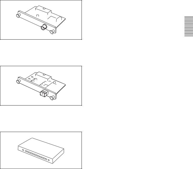
BRBK-302 SDI Card
Insert the card into the camera or the Optical Multiplex Unit to allow output of a signal conforming to SMPTE259M serial digital interface standards.
BRBK-303 Optical Multiplex Card
Insert the card into the camera to allow high-bit multiplex transfer via optical fiber (video, external video sync and control signals).
Video Switcher (commercially available)
It switches the video signal input of multiple cameras.
Overview
System Components |
9 |
|
|
Overview
System Configuration
The BRC-300/300P 3CCD Color Video Camera has various system configuration capabilities using optional products. This section describes six typical system examples with the required components and the main usage of each system.
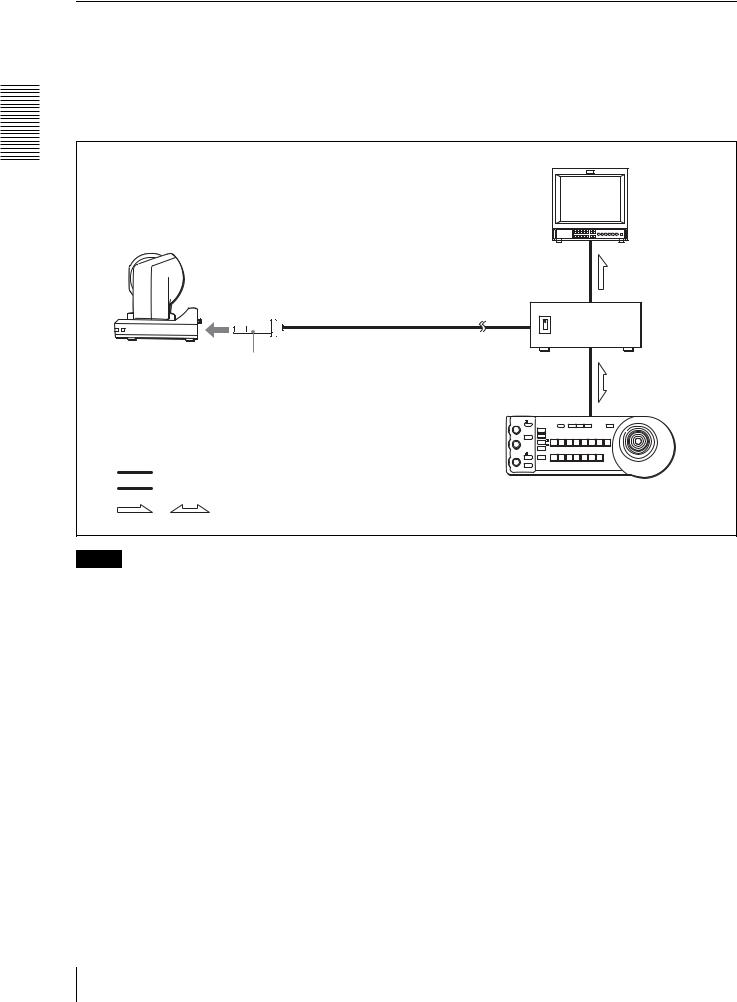
Operating a BRC-300/300P Camera Using the Supplied Remote Commander
This system allows you:
To operate the camera readily from a short distance
System configuration
BRC-300/300P |
|
|
Video monitor, VTR, etc. |
Remote Commander |
Video signal |
(supplied) |
Signal flow |
|
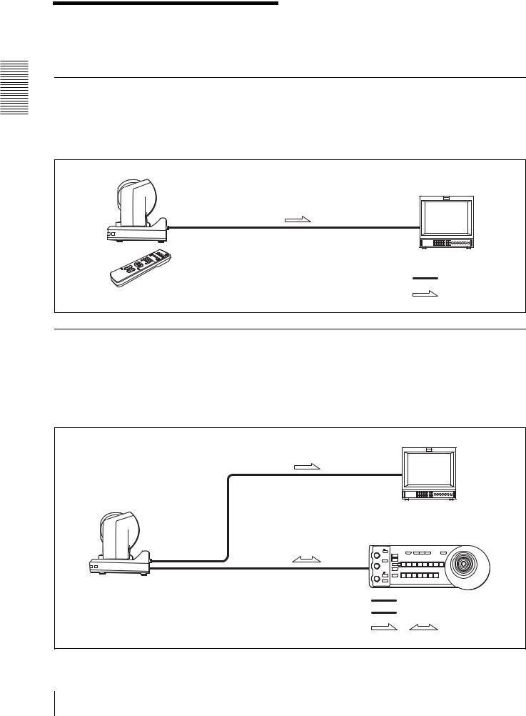
Operating a BRC-300/300P Camera Using the RM-BR300 Remote Control
Unit
This system allows you:
To perform pan/tilt and zoom operations comfortably using the joystick of the Remote Control Unit
System configuration
Video monitor, VTR, etc. |
|
BRC-300/300P |
|
RM-BR300 Remote Control Unit |
|
Video signal |
|
Remote Control (VISCA) signal |
|
, |
Signal flow |
10 System Configuration
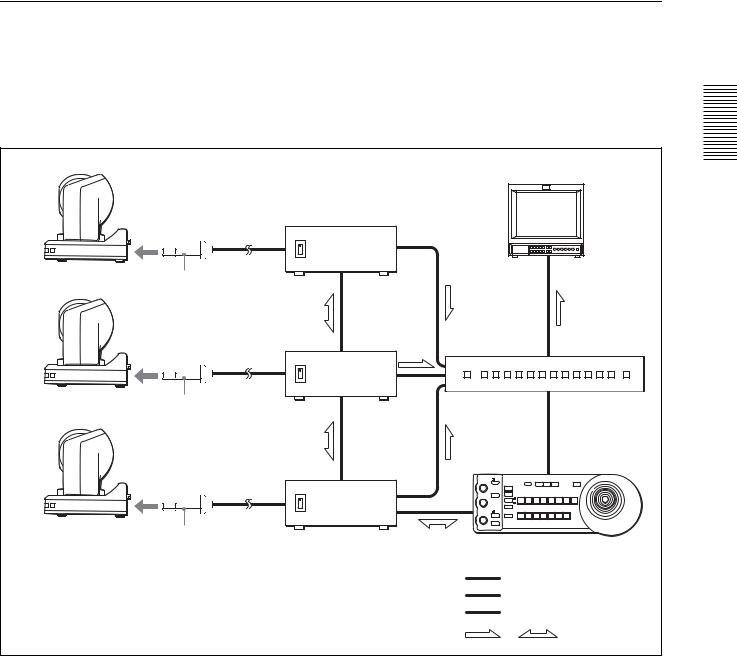
Operating Multiple BRC-300/300P Cameras Using the RM-BR300 Remote
Control Unit
This system allows you:
• To operate up to seven cameras remotely using a single Remote Control Unit
• To perform pan/tilt and zoom operations comfortably using the joystick
System configuration |
|
|
|
BRC-300/300P |
|
Overview |
|
Video monitor, VTR, etc. |
|||
|
|||
BRC-300/300P |
|
|
|
|
Video switcher |
|
|
BRC-300/300P |
|
|
|
RM-BR300 Remote Control Unit |
|
||
Video signal |
|
|
|
Remote control (VISCA) signal |
|
||
Tally/contact signal |
|
||
, |
Signal flow |
|
|
System Configuration |
11 |
|
|
Operating a BRC-300/300P Camera from a Long Distance
This system allows you:
•To operate the camera remotely from a distance up to 500 m (1,640 feet)
•To perform pan/tilt and zoom operations comfortably using the joystick
• To transmit the video signal and control signal of the camera to a distant place using the Optical Fiber Cable
System configuration |
|
||
|
|
Video monitor, VTR, etc. |
|
Overview |
|
|
|
BRC-300/300P |
|
|
|
|
CCFC-M100 Optical Fiber Cable |
BRU-300/300P |
|
|
|
Optical Multiplex |
|
|
|
Unit |
|
|
BRBK-303 Optical Multiplex Card |
|
|
Video signal |
RM-BR300 Remote Control Unit |
||
Remote control (VISCA) signal |
|||
|
|||
, |
Signal flow |
|
|
Notes
•The BRC-300/300P camera does not operate if nothing is connected to the BRBK-303 Optical Multiplex Card inserted into the camera. To operate the camera, connect the BRU-300/300P Optical Multiplex Unit to the BRBK303 using the CCFC-M100 Optical Fiber Cable and turn on the power of the BRU-300/300P.
•When the BRBK-303 Optical Multiplex Card is inserted into the BRC-300/300P camera, the EXT SYNC connector, VISCA RS-232C IN/OUT connectors and VISCA RS-422 connector on the rear of the camera and the BOTTOM switches on the bottom of the camera are disabled. Use the connectors and switches on the rear of the BRU-300/300P Optical Multiplex Unit instead.
12 System Configuration
Operating Multiple BRC-300/300P Cameras from a Long Distance
This system allows you:
•To operate up to seven cameras remotely from a distance up to 500 m (1,640 feet)
•To perform pan/tilt and zoom operations comfortably using the joystick
• To transmit the video signal and control signal of the cameras to a distant place using the Optical Fiber Cable
System configuration |
|
|
|
|
BRC-300/300P |
|
Video monitor, VTR, etc. |
Overview |
|
|
|
|||
|
|
BRU-300/300P |
|
|
|
|
|
|
|
|
CCFC-M100 |
Optical Multiplex |
|
|
|
|
|
|
|
|
Optical Fiber Cable |
|
|
|
|
BRBK-303 Optical |
|
|
|
BRC-300/300P |
Multiplex Card |
|
|
|
|
|
BRU-300/300P |
Video switcher |
|
|
|
|
|
|
|
CCFC-M100 |
|
|
|
|
BRBK-303 |
|
|
|
BRC-300/300P |
|
|
|
|
|
|
BRU-300/300P |
|
|
|
CCFC-M100 |
|
|
|
|
BRBK-303 |
RM-BR300 Remote Control Unit |
|
|
|
|
|
||
|
|
Video signal |
|
|
|
|
Remote control (VISCA) signal |
|
|
|
|
Tally/contact signal |
|
|
|
|
, |
Signal flow |
|
System Configuration |
13 |
|
|
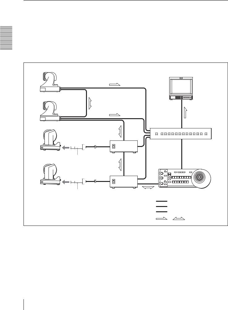
Using BRC-300/300P Cameras and VISCA-controllable Cameras in the
Same System
This system allows you:
•To operate up to seven cameras supporting the VISCA protocol such as EVI-D30/D30P, EVI-D70/D70P and EVID100/D100P remotely using a single RM-BR300 Remote Control Unit
•To perform pan/tilt and zoom operations comfortably using the joystick
•To control the BRC-300/300P cameras remotely from a distance up to 500 m (1,640 feet) by transmitting the video signal and control signal using the Optical Fiber Cable
Overview |
System configuration |
|
|
|
|
|
|
|
|
|
VISCA-controllable camera |
|
|
|
|
|
|
Video monitor, VTR, etc. |
|
|
VISCA-controllable camera |
|
|
|
|
BRC-300/300P |
|
|
Video switcher |
|
|
|
|
|
|
|
BRU-300/ |
|
|
|
|
300P |
|
|
|
CCFC-M100 |
|
|
|
|
BRBK-303 |
|
|
|
|
BRC-300/300P |
|
|
|
|
CCFC-M100 |
|
|
|
|
Optical Fiber |
|
|
|
|
Cable |
|
|
|
|
BRBK-303 Optical |
BRU-300/300P |
RM-BR300 Remote Control Unit |
|
|
Multiplex Card |
Optical Multiplex Unit |
|
|
|
|
|
Video signal |
|
|
|
|
Remote control (VISCA) signal |
|
|
|
|
Tally/contact signal |
|
|
|
|
, |
Signal flow |
14 System Configuration

Location and Function
of Parts
Camera
Front
12 3
 POWER
POWER
IR
STANDBY
45
ALens
A wide conversion lens (not supplied) can be attached.
BTally lamp
Lights in red when a VISCA tally command is received or the camera is selected by the RMBR300 Remote Control Unit (not supplied).
Flashes at intervals of about 0.5 seconds if the rotating speed of the cooling fan motor is lowered or the motor has stopped regardless of on/off of the tally lamp.
CRemote sensor
This is the sensor for the supplied Remote Commander.
DPOWER lamp
Lights when the camera is connected to an AC outlet using the supplied AC power adaptor and AC power cord.
Flaches in green when the camera receives an operation command from the supplied Remote Commander.
ESTANDBY lamp
Lights when the camera is turned off using the
Remote Commander.
Rear
678 9
|
1 |
2 |
3 |
R |
1 2 3 4 5 6 7 8 9 |
|
OFF |
ON |
|
|
|
|
|
75 |
IR SELECT |
|
VISCA RS-422 |
! |
||
|
|
|
|
|
||
EXT SYNC IN |
VIDEO |
|
S VIDEO IN VISCA RS-232C OUT |
DC IN |
||
|
12V |
|||||
0 qa qs qd qf qg qh
F75-ohm termination switch
This switch is used when an external sync signal is used. Set it to OFF when this camera is in the middle of a daisy chain connection of multiple cameras. Set it to ON when the camera is at the end of a daisy chain connection.
GIR SELECT switch
Select the camera number when you operate multiple cameras with the same Remote Commander.
HRemote sensor
This is the sensor for the supplied Remote Commander.
IVISCA RS-422 connector
Used for VISCA control.
For connection to the VSCA RS-422 connector, see “Using the VISCA RS-422 Connector Plug” on page 68.
JEXT SYNC IN connector
Accepts external video sync signals.
KTVIDEO connector
Supplies the images as composite signals.
L  S VIDEO connector
Supplies the images as Y/C separate (S video) signals.
Overview
Location and Function of Parts |
15 |
|
|

Overview
MVISCA RS-232C IN connector
Connect to the RM-BR300 Remote Control Unit (not supplied). When you connect multiple cameras, connect it to the VISCA RS-232C OUT connector of the previous camera in the daisy chain connection.
NVISCA RS-232C OUT connector
When you connect multiple cameras, connect it to the VISCA RS-232C IN connector of the next camera in the daisy chain connection.
ODC IN 12V connector
Connect the supplied AC power adaptor.
PCard slot
Insert an optional interface card such as BRBK301, BRBK-302 and BRBK-303.
The slot cover is attached to the camera at the factory.
Bottom
qj |
qk |
|
ql |
||||
|
|
|
|
|
|
|
|
|
|
|
|
|
|
|
|
|
|
|
|
|
|
|
|
|
|
|
|
|
|
|
|
|
|
|
|
|
|
|
|
|
|
|
|
|
|
|
|
|
|
|
|
|
|
|
|
QCeiling bracket mounting screw holes
When you install the camera to the ceiling, secure the supplied ceiling bracket to these holes using the supplied four screws.
For installation, see “Installing the Camera on the Ceiling” on page 43.
RTripod screw holes (1/4-20UNC)
When you install the camera to a tripod, secure the tripod to these holes.
SBOTTOM switches
Used for the RS-232C/RS-422 selection, baud rate selection, remote control signal output on/off and camera address setting.
For details, see “Setting of the BOTTOM switches” on page 16.
Setting of the BOTTOM switches
|
|
1 |
1 |
O |
2 |
|
||
2 |
N |
3 |
4 |
|
|
3 |
|
|
|
|
4 |
1 |
O |
5 |
3 |
N |
|
2 |
|
|
4 |
|
|
1Switch 1 (No Connection)
Always keep it OFF.
2Switch 2 (RS-232C/RS-422 selector)
Set to ON for RS-422, or OFF for RS-232C.
3Switch 3 (Communication baud rate selector)
Set to ON for 38400bps, or OFF for 9600bps.
4Switch 4 (Infrared signal output switch)
Set to ON to enable an infrared signal output, or OFF to disable the output.
5Camera address selectors
Set the address of the camera.
Normally set to "0". With this setting, addresses are assigned to the cameras automatically in the connected order by pressing the POWER button while holding down the RESET button on the RMBR300 Remote Control Unit.
You can assign the camera address "1" to "7" manually by setting these selectors as follows:
Camera |
0 |
1 |
2 |
3 |
4 |
5 |
6 |
7 |
address |
|
|
|
|
|
|
|
|
|
|
|
|
|
|
|
|
|
Switch 1 |
OFF |
ON |
OFF |
ON |
OFF |
ON |
OFF |
ON |
|
|
|
|
|
|
|
|
|
Switch 2 |
OFF |
OFF |
ON |
ON |
OFF |
OFF |
ON |
ON |
|
|
|
|
|
|
|
|
|
Switch 3 |
OFF |
OFF |
OFF |
OFF |
ON |
ON |
ON |
ON |
|
|
|
|
|
|
|
|
|
Note
Switch 4 is not used.
16 Location and Function of Parts

Remote Commander (supplied)
|
|
|
POWER |
|
|
|
|
|
6 |
1 |
CAMERA SELECT |
|
||
1 |
2 |
3 |
|
|
2 |
FOCUS |
|
|
|
AUTO |
|
MANUAL |
|
|
|
FAR |
NEAR |
|
|
|
DATA SCREEN |
|
BACK LIGHT |
7 |
3 |
|
|
|
|
|
STD |
REV |
|
|
|
1 |
2 |
3 |
|
|
4 |
5 |
6 |
8 |
|
PRESET |
|
RESET |
|
|
POSITION |
|
|
|
|
PAN-TILT |
|
|
|
4 |
HOME |
|
|
|
|
|
|
PAN-TILT |
|
|
|
|
RESET |
9 |
|
SLOW ZOOM FAST |
|||
|
|
|||
|
T |
|
T |
q; |
|
W |
W |
||
|
|
|||
L/R
5 |
DIRECTION SET |
|
RM-EV100 |
ACAMERA SELECT buttons
Press the button corresponding to the camera you want to operate with the Remote Commander. The camera number can be set using the IR SELECT switch on the rear of the camera.
Note
If two or more cameras are adjacent and have the same camera number, they are operated simultaneously with the same Remote Commander. When you install the cameras close to each other, set different camera numbers.
For the camera number setting, see “Operating Multiple Cameras with the Remote Commander” on page 32.
BFOCUS buttons
Used for focus adjustment.
Press the AUTO button to adjust the focus automatically. To adjust the focus manually, press the MANUAL button, and adjust it with the FAR and NEAR buttons.
CDATA SCREEN button
Press this button to display the main menu. Press it again to turn off the menu. If you press the button when a lower-level menu is selected, the display goes back to a higher-level menu.
Note
Pan/tilt and zoom operations are disabled when the menu is displayed.
DPAN-TILT buttons
Press the arrow buttons to perform panning and tilting. Press the HOME button to face the camera back to the front.
EL/R DIRECTION SET button
Hold down this button and press the REV button to change the direction of the camera movement opposite to that indicated by the arrow of the B/b buttons.
To reset the direction of the camera movement, press the STD button while holding down this button.
FPOWER switch
Press this button to turn on/off the camera when the camera is connected to an AC outlet.
GBACK LIGHT button
Press this button to enable the backlight compensation. Press it again to disable the backlight compensation.
HPOSITION buttons
Hold down the PRESET button and press button 1 to 6 to store the current camera direction, zooming, focus adjustment and backlight compensation in the memory of the pressed number button.
To erase the memory contents, hold down the RESET button and press button 1 to 6.
IPAN-TILT RESET button
Press this button to reset the pan/tilt position.
JZOOM buttons
Use the SLOW button to zoom slowly, and the FAST button to zoom quickly.
Press the T (telephoto) side of the button to zoom in, and the W (wide angle) side to zoom out.
Overview
Location and Function of Parts |
17 |
|
|
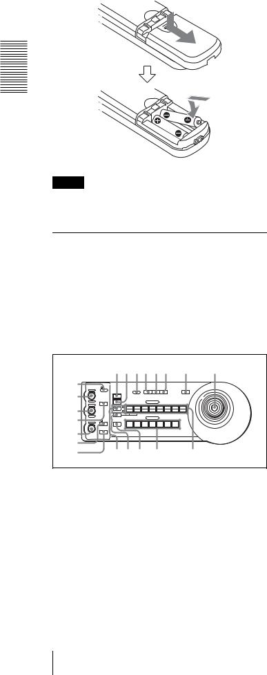
Installing batteries
Two R6 (size AA) batteries (not supplied)
Overview
Caution
To avoid risk of explosion, use R6 (size AA) manganese or alkaline batteries.
RM-BR300 Remote Control Unit (not supplied)
This manual explains the operations of the RM-BR300 Remote Control Unit when it is used with BRC-300/ 300P cameras.
For operations with other cameras, refer to the Operating Instructions supplied with the RM-BR300.
Front
890qaqsqd qf qg
1 |
|
|
|
|
|
|
|
|
|
|
|
|
|
|
VALUE |
LOCK |
|
|
PANEL |
|
BLACK |
PAN-TILT |
ONE PUSH |
|
|
||
2 |
– |
+ |
|
|
|
|
|
MENU |
|||||
|
|
|
|
|
|
LIGHT |
|
LIGHT |
RESET |
AWB |
|
|
|
|
|
|
|
RESET |
|
|
|
|
|
|
|
|
|
|
|
R |
|
PRESET |
|
|
|
POSITION |
|
|
|
|
|
|
|
|
MODE |
|
|
|
|
|
|
|
|||
|
BRIGHT |
|
|
|
|
|
|
|
|
|
|
|
|
3 |
|
|
|
SHIFT |
1 |
2 |
3 |
|
4 |
5 |
6 |
7 |
8 |
|
|
|
|
9 |
10 |
11 |
|
12 |
13 |
14 |
15 |
16 |
|
– |
+ |
|
L/R |
STD |
REV |
|
|
|
|
|
|
|
|
|
|
|
|
|
|
|
|
|
|
||||
4 |
|
B |
|
DIRECTION |
|
|
|
CAMERA |
|
|
|
|
|
|
|
|
|
|
|
|
|
|
|
|
|||
|
|
AUTO |
|
|
|
|
|
|
|
|
|
|
|
FOCUS |
AUTO |
POWER |
1 |
2 |
3 |
|
4 |
5 |
6 |
7 |
|
||
|
|
MANUAL |
|
|
|||||||||
5 NEAR |
|
ONE PUSH |
|
|
|
|
|
|
|
|
|
|
|
FAR |
AF |
|
|
|
|
|
|
|
|
|
|
||
6 |
|
|
|
|
|
|
|
|
|
|
|
|
|
7 |
|
|
|
qhqjqk |
|
ql |
|
|
w; |
||||
ALOCK button and indicator
Press the LOCK button for more than one second, and the LOCK indicator lights and the values set by the VALUE/R, BRIGHT/B and FOCUS controls are locked. (The indicators of the locked controls are turned off.).
The AUTO/MANUAL button is also disabled. Press the LOCK button for more than one second again to unlock the controls and buttons.
BVALUE/R control
When the brightness adjustment mode is selected with the MODE button (with the VALUE indicator lit), this control adjusts the value of the item (SHUTTER or IRIS) selected with the menu of the camera.
When the white balance adjustment mode is selected with the MODE button (with the R indicator lit), this control adjusts the R. GAIN (red gain).
When the VALUE indicator is lit, the function of the control varies according to the setting of the MODE button. For details, see “Functions of the VALUE and BRIGHT controls” on page 39.
CBRIGHT/B control
When the brightness adjustment mode is selected with the MODE button (with the BRIGHT indicator lit), this control adjusts the value of the brightness of the camera, etc.
When the white balance adjustment mode is selected with the MODE button (with the B indicator lit), this control adjusts the B. GAIN (blue gain).
When the BRIGHT indicator is lit, the function of the control varies according to the setting of the MODE button. For details, see “Functions of the VALUE and BRIGHT controls” on page 39.
DMODE button
Press this button to select the function of the VALUE/R control and BRIGHT/L control. When the brightness adjustment mode is selected, the VALUE and BRIGHT indicators are lit. When the white balance adjustment mode is selected, the R and B indicators are lit.
EFOCUS control
Turn this control counterclockwise (toward NEAR) to focus on a near subject, and clockwise (toward FAR) to focus on a far subject.
FAUTO/MANUAL button and AUTO indicator
Press this button to select focus mode AUTO or MANUAL.
When AUTO is selected, the AUTO indicator lights and the FOCUS control and the ONE PUSH AF button are disabled.
When MANUAL is selected, the FOCUS control and the ONE PUSH AF button are enabled (with the FOCUS indicator lit).
GONE PUSH AF button
Press this button to perform the one-push auto focus function.
18 Location and Function of Parts

HRESET button
Hold down this button and press POSITION button 1 to 6, and the memory of the camera corresponding to the pressed POSITION button is cleared to the factory-preset conditions.
When multiple cameras are connected, hold down this button and press the POWER button to set the camera addresses.
IPRESET button
Hold down this button and press POSITION button 1 to 6, and the current camera settings are stored in the memory of the camera corresponding to the pressed POSITION button.
JPANEL LIGHT button
Press this button to illuminate all the POSITION buttons and CAMERA buttons. Press the button again to turn off the illumination.
KBACK LIGHT button
Press this button to enable the backlight compensation function of the camera. Press it again to disable the function.
LPAN-TILT RESET button
Press this button to reset the pan/tilt position of the camera to the initial conditions.
MONE PUSH AWB button
When ONE PUSH is selected with the WHITE BALANCE menu of the camera, press this button to perform the one-push white balance adjustment.
NMENU button
Press this button to display or turn off the menu of the camera.
OJoystick
When the menu of the camera is not displayed
The joystick is used for pan/tilt and zoom operations.
When you incline the joystick right and left, the camera pans.
When you incline it forward or backward, the camera tilts.
The pan/tilt speed changes according to the angle of the inclination.
When you release the joystick, the camera movement stops.
When you turn the dial on the upper part of the joystick clockwise, the subject becomes larger (zoom in). When you turn it counterclockwise, the subject becomes smaller (zoom out).
When you press the button on the top of the joystick for one or two seconds with or without the menu displayed, the pan/tilt/zoom are reset and the camera returns to the front.
When the menu of the camera is displayed
The joystick is used for menu operations. Inclining the joystick right, left, forward and backward has the same function as pressing the arrow buttons of the supplied Remote Commander. Pressing the button on the top of the joystick has the same function as pressing the HOME button on the Remote Commander.
PSHIFT button and indicators
Press this button to select the function of the POSITION buttons for positions 1 to 8 or positions 9 to 16.
The upper indicator lights for positions 1 to 8, and the lower indicator for positions 9 to 16.
QL/R DIRECTION button
Hold down this button and press POSITION button 2 (REV) to reverse the pan direction to the direction in which you incline the joystick. To reset the direction, hold down this button and press POSITION button 1 (STD).
RPOWER button
Press this button to light the CAMERA button(s) corresponding to the status of the connected camera(s).
Blue: The power of the camera is on.
Yellow green: The camera is in standby mode. Off: No camera is connected.
Hold down this button and press CAMERA button 1 to 7 to turn on/off the power of the camera corresponding to the pressed button.
SCAMERA buttons
Press one of the buttons to select the camera from among those connected. The selected CAMERA button lights in blue.
TPOSITION buttons
You can store the various camera settings such as the pan, tilt and zoom positions to the memory of the camera corresponding to each POSITION button, and load the settings in the memory.
Overview
Location and Function of Parts |
19 |
|
|

Overview
Rear/Bottom |
|
|
|
|
|
MODE RS-232C |
VISCA |
RS-422 |
TALLY/CONTACT |
CONTACT(TALLY) ! ON/OFF |
|
|
|
|
|
|
TALLY |
|
1 |
9 |
1 |
9 |
CONTACT DC IN 12V |
|
|
|
|
|
|
wa ws wd |
|
wf wgwh wj wk |
|||
UMODE selector
Select the position corresponding to the VISCAcontrollable camera to be connected.
Switch position |
Camera mode |
0 |
Automatically selected (default) |
|
|
1 |
BRC-300/300P |
|
|
2 |
EVI-D70/D70P |
|
|
3 |
EVI-D100/D100P |
|
|
4 |
EVI-D30/D30P |
|
|
Note
Use position 1 to 4 when all the connected cameras are of the same model.
VVISCA RS-232C connector
Connect to the VISCA RS-232C IN connector of the camera or the BRU-300/300P Optical Multiplex Unit.
WVISCA RS-422 connector
Connect to the VISCA RS-422 connector of the camera or the BRU-300/300P Optical Multiplex Unit.
An RS-422 connector plug is attached at the factory.
XTALLY/CONTACT connector
This connector is used for the tally lamp input or the contact output.
Select the function of the connector using the TALLY/CONTACT selector.
An RS-422 connector plug is attached at the factory.
YTALLY/CONTACT selector
Select the function of the TALLY/CONTACT connector.
TALLY: The tally lamp of the camera selected with the connected switcher lights.
CONTACT: The contact output corresponding to the camera address selected with the Remote Control Unit is short-circuited against the connected switcher.
CONTACT (TALLY): The contact output corresponding to the camera address selected with the Remote Control Unit is short-circuited against the connected switcher and the tally lamp of the camera selected with the connected switcher lights.
Note
Change the setting of the selector before you turn on the power of the Remote Control Unit. Otherwise, the setting is not effective.
wh DC IN 12V connector
Connect the supplied AC power adaptor.
wj DIP switches (bottom)
Switch 1 (RS-232C/RS-422 selector)
Set to ON for RS-422, or OFF for RS-232C.
Switch 2 (Communication baud rate selector)
Set to ON for 38400bps, or OFF for 9600bps.
Note
Set the DIP switches before you turn on the power of the Remote Control Unit. Otherwise, the setting is not effective.
wk ON/OFF switch
Press this switch to turn on/off the Remote Control Unit.
20 Location and Function of Parts
BRU-300/300P Optical Multiplex Unit (not supplied)
Front
1 2
APower switch
Turns on/off the power of the Optical Multiplex Unit.
BPower indicator
Lit in green: The Optical Multiplex Unit is in normal operation.
Lit in red: The power of the camera is turned off. Turn it on.
Flashing in red: Abnormal operation of the Optical Multiplex Unit. Display the composite video signal on the monitor and check the error message. Check also the connection.
For the error message, see “List of Messages” on page 54.
Rear
3 |
4 |
||||||
|
|
|
|
|
|
|
|
|
|
|
|
|
|
|
|
|
|
|
|
|
|
|
|
|
|
|
|
|
|
|
|
|
|
|
|
|
|
|
|
~
AC IN
|
FUNCTION |
IN |
OUT |
|
|
|
1 |
6 |
|
||
|
|
|
|
||
|
VISCA RS-422 |
|
|
|
|
IN EXT SYNC OUT |
S VIDEO |
|
VISCA RS-232C |
CAMERA |
|
5 6 7 8 9 0qaqsqd
CCard slot
Insert an optional interface card such as BRBK-301 or BRBK-302.
The slot cover is attached to the camera at the factory.
DAC IN connector
Connect the supplied AC power cord.
EEXT SYNC IN connector
Accepts external video sync signals.
FEXT SYNC OUT connector
Supplies external video sync signals.
GComposite video output connector
Supplies the images from the camera as composite signals.
H S VIDEO connector
Supplies the images from the camera as Y/C separate (S video) signals.
IVISCA RS-422 connector
Connect to the VISCA RS-422 connector of the camera or another BRU-300/300P Optical Multiplex Unit.
For the connection to the VISCA RS-422 connector, see “Using the VISCA RS-422 Connector Plug” on page 68.
JVISCA FUNCTION switches
These switches are used for the VISCA communication settings.
Switch 1 (RS-232C/RS-422 selector)
Set to ON for RS-422, or OFF for RS-232C.
Switch 2 (Communication baud rate selector)
Set to ON for 38400bps, or OFF for 9600bps.
Overview
Location and Function of Parts |
21 |
|
|
Loading...