


1080i

2005 Sony Corporation
2-549-780-11(1)
Digital HD
Videocassette
Recorder
HVR-M10U/M10N/M10E/M10P
Operating Instructions
2
WARNING
To prevent fire or shock hazard, do not
expose the unit to rain or moisture.
To avoid electrical shock, do not open the
cabinet. Refer servicing to qualified per-
sonnel only.
This symbol is intended to alert the user to the
presence of uninsulated “dangerous voltage”
within the product’s enclosure that may be of
sufficient magnitude to constitute a risk of
electric shock to persons.
This symbol is intended to alert the user to the
presence of important operating and
maintenance (servicing) instructions in the
literature accompanying the appliance.
Owner’s record
The model number is located at the front of the unit and the
serial number on the left. Record the serial number in the
space provided below. Refer to these numbers whenever you
call upon your Sony dealer regarding this product.
Model No. HVR-
Serial No. ______________________
Model No. AC-L15A
Serial No. ______________________
For customers in the U.S.A.
HVR-M10U only
If you have any questions about this product, you may
call: Sony’s Business Information Center (BIC) at 1-800-
686-SONY (7669)
or Write to: Sony Customer Information Services Center
6900-29 Daniels Parkway, PMB 330 Fort
Myers, Florida 33912
Declaration of Conformity
Trade Name: SONY
Model: HVR-M10U
Responsible Party: Sony Electronics Inc.
Address: 16450 W. Bernardo Dr, San
Diego, CA 92127 U.S.A.
Telephone Number: 858-942-2230
This device complies with Part 15 of the FCC Rules.
Operation is subject to the following two conditions:
(1) This device may not cause harmful interference, and
(2) this device must accept any interference received,
including interference that may cause undesired
operation.

3
CAUTION
You are cautioned that any changes or modifications not
expressly approved in this manual could void your authority
to operate this equipment.
NOTE:
This equipment has been tested and found to comply with
the limits for Class B digital device, pursuant to Part 15 of the
FCC Rules.
These limits are designed to provide reasonable protection
against harmful interference in a residential installation.
This equipment generates, uses, and can radiate radio
frequency energy and, if not installed and used in
accordance with the instructions, may cause harmful
interference to radio communications.
However, there is no guarantee that interference will not
occur in a particular installation. If this equipment does cause
harmful interference to radio or television reception, which
can be determined by turning the equipment off and on, the
user is encouraged to try to correct the interference by one or
more of the following measures:
– Reorient or relocate the receiving antenna.
– Increase the separation between the equipment and
receiver.
– Connect the equipment into an outlet on a circuit different
from that to which the receiver is connected.
– Consult the dealer or an experienced radio/TV technician
for help.
NOTICE FOR CUSTOMERS IN THE
UNITED KINGDOM
HVR-M10E only
A moulded plug complying with BS1363 is fitted to this
equipment for your safety and convenience.
Should the fuse in the plug supplied need to be replaced, a
fuse of the same rating as the supplied one and approved by
ASTA or BSI to BS1362 (i.e., marked with
or mark)
must be used.
If the plug supplied with this equipment has a detachable
fuse cover, be sure to attach the fuse cover after you change
the fuse. Never use the plug without the fuse cover. If you
should lose the fuse cover, please contact your nearest Sony
service station.
English
For the customers in Europe
HVR-M10E only
This product with the CE marking complies with both the
EMC Directive (89/336/EEC) and the Low Voltage Directive
(73/23/EEC) issued by the Commission of the European
Community.
Compliance with these directives implies conformity to the
following European standards:
•EN60065 :Product Safety (Supplied AC Adapter only)
•EN55103-1 :Electromagnetic Interference (Emission)
•EN55103-2 :Electromagnetic Susceptibility (Immunity)
This product is intended for use in the following
Electromagnetic Environment(s):
E1 (residential), E2 (commercial and light industrial), E3
(urban outdoors) and E4 (controlled EMC environment ex. TV
studio).
ATTENTION
The electromagnetic fields at the specific frequencies may
influence the picture and sound of this unit.
Applicable only to ports interfacing with cables whose total
length according to the manufacturer's functional
specification may exceed 1 m.
For the customers in the Nederland
Voor de klanten in Nederland
Dit apparaat bevat een vast ingebouwde batterij die niet
vervanden hoeft te worden tijdens de levensduur van het
apparaat.
Raadpleeg uw leverancier indien de batterij toch vervangen
moet worden.
De batterij mag alleen vervangen worden door vakbekwaam
servicepersoneel.
Gooi de batterij niet weg maar lever deze in als klein
chemisch afval (KCA).
Lever het apparaat aan het einde van de levensduur in voor
recycling, de batterij zal dan op correcte wijze verwerkt
worden.
Caution
Television programs, films, video tapes and other materials
may be copyrighted. Unauthorized recording of such material
may be contrary to the provisions of the copyright laws. Also,
use of this recorder with cable television transmission may
require authorization from the cable television transmission
and/or program owner.

4 Table of Contents
Table of Contents
Table of Contents
Chapter1
Overview
Features .............................................................................6
Location and Function of Parts .......................................8
Front Panel .......................................................................... 8
Section behind the Operation Panel ................................. 10
Inside of the Front Panel ................................................... 14
Rear Panel ......................................................................... 15
Supplied Remote Commander .......................................... 17
Displaying Various Data .................................................19
Chapter2
Playback and
Recording
Notes on Power Supply and Video Cassettes .............. 21
Preparing the Power Supply .............................................. 22
Inserting/Ejecting Cassettes .............................................. 22
Notes on Playback/Recording ........................................... 23
Installing the Unit Vertically ............................................. 24
Playback...........................................................................25
Connections for Playback.................................................. 25
Settings for Playback......................................................... 27
Playback Procedures ......................................................... 27
Playback Functions ........................................................... 27
Using the Unit as a Videocassette Recorder ................ 31
Connections for Recording................................................ 31
Settings for Recording....................................................... 33
Recording Procedures ....................................................... 34
Recording Functions ......................................................... 34
Chapter3
Dubbing/Editing
Dubbing to another equipment ......................................35
Connections for Dubbing .................................................. 35
Dubbing procedures .......................................................... 37
Editing (Connecting with a Personal Computer) ......... 38
Connecting the Unit to a Personal Computer .................... 38
Preparations ....................................................................... 39
Setting the Time Code and User Bits ............................40
Using the Internal Time Code Generator .......................... 40
Audio Dubbing ................................................................ 43

Table of Contents 5
Chapter4
Adjusting and
Setting Through
Menus
Operating the Menus ...................................................... 45
Menu Organization............................................................ 46
Menu Contents .................................................................. 47
Chapter5
Maintenance
Troubleshooting ..............................................................54
General Operation Troubles .............................................. 54
Batteries/Power sources .................................................... 55
Cassette tapes .................................................................... 56
Playback ............................................................................ 57
Recording/Dubbing ........................................................... 58
Warning indicators and messages ................................ 59
Self-diagnosis display/Warning Indicators........................ 59
Alarm Messages ................................................................ 60
Notes on Use ...................................................................61
Notes on the Videocassette Recorder ................................ 61
Cleaning of the Video Heads ............................................. 61
Notes on the Video Cassettes ............................................ 62
Notes on the LCD Screen .................................................. 62
About Moisture Condensation .......................................... 63
Digital Hours Meter .......................................................... 63
About the Built-in Rechargeable Battery .......................... 64
Using your Videocassette Recorder abroad ....................... 64
Appendix
Using the optional battery ..............................................65
About the “InfoLITHIUM” battery pack ......................... 67
Compatibility of HDV, DVCAM, and DV Formats .......... 68
About i.LINK .................................................................... 72
Specifications ..................................................................73
Index .................................................................................75
Submenu Index ............................................................... 76

6 Chapter 1 Overview
Chapter 1 Overview
Chapter1
Overview
Features
The HVR-M10U/M10N/M10E/M10P is a digital HD
videocassette recorder supporting HDV format.
Offering the DVCAM/DV format, this unit produces
stable, superior picture quality by digital processing
and separating image signals into color difference
signals and a luminance signal (component video).
This unit provides the i.LINK (
HDV/DV) jack, the
COMPONENT OUT jacks, the S VIDEO IN/OUT
jacks, the composite IN/OUT jacks, and the AUDIO
IN/OUT jacks. These jacks allow you to connect other
equipment like non-linear editors. Additionally, it
comes with a 3.5-type color LCD (liquid crystal
display) monitor, you can easily check your recorded
images, menus, and the audio level meters.
The main features of this unit are described below.
HDV format
The unit can perform HDV (High-Definition Digital
Video) recording and playback on a DV format video
cassette.
The compression system of HDV format is the
MPEG2 system adopted in the high-definition
broadcasting and the Blu-ray Disk System.
The unit adopts the 1080 scanning lines (interlace)
(1080i)/1440 × 1080 pixels format of the HDV
specifications. The recording bit rate is approximately
25 Mbps. This unit is equipped with an i.LINK digital
interface and can be digitally connected with HDV-
compatible televisions or personal computers.
DVCAM/DV format
DVCAM is based on the consumer DV format, which
uses the 4:1:1 component digital format (60i) or the
4:2:0 format (50i), and provides a
1
/4-inch digital
recording format for professional use. This unit
provides both DVCAM format recording/playback and
DV format in SP mode recording/playback.
For details, see “Compatibility of HDV, DVCAM and DV
Format” on page 68.
Compatible with both 1080/60i (NTSC) and
1080/50i (PAL) systems
The unit is compatible with 50i and 60i systems. You
can switch these input signals using the menu setting
(p. 53). This compatibility allows you to record
(download) or play back (upload) both 50i and 60i
formatted signals with your VCR, personal computer,
or other equipment.
However, the unit cannot convert the color system of
the signals.
The unit set in 60i system has a field frequency of
59.94Hz.
Chapter 1 Overview 7
Chapter 1 Overview
High definition downconvert function
When you want to playback a tape recorded in the
HDV format, you can dowoncovert any images to
output them. This function allows you to preview
recorded-images on a regular monitor. Also, you can
select an aspect ratio from the SQUEEZE, LETTER
BOX, or EDGE CROP (side cut).
16:9 Built-in color LCD monitor
The unit has a 3.5-type color LCD (liquid crystal
display) monitor that lets you verify images on the
spot. You can see the setup menus, audio levels, and
system statuses. Menus and data can be superimposed
over the picture being displayed.
Multiple input/output interfaces
The HDV/DV jack, COMPONENT OUT jacks
(output only), S VIDEO jacks and VIDEO jacks and
AUDIO jacks are equipped on the unit and enable the
connection with various devices.
A variety of buttons and switches for VCR
operations
This unit provides a variety of buttons for VCR
operations, such as the INPUT SELECT switch, the
AUDIO REC LEVEL (VOL), the PHONE LEVEL
control knob, and the STATUS CHECK button.
Time code and user bits
On this unit, you can use time code and user bits.
Using the menu, these can be set easily.
Screen Language Setting
You can select the language.
The default setting is indicated in English.
See page 52 to change the screen language.
Compatible with InfoLITHIUM series
InfoLITHIUM (L series) batteries allow you to use a
DC power supply.
InfoLITHIUM batteries are lithium batteries to
communicate with compatible equipment. They
display how much battery power has been remained.
Compact size allowing vertical installation
The compact size of the unit allows installation in a
vertical position and saves space. During non-linear
editing, you can install the unit in a vertical position
next to the personal computer and save working space.
Fan-less design
To provide noise-free operation, this unit has been
designed without using an exhaust fan.
Easy maintenance functions
• Self-diagnostics/alarm functions: The system
automatically detects an invalid operation, an invalid
connection or a malfunction, and displays a
description, a cause and a recovery method on the
LCD monitor and outputs the data as analog video
signals.
• Digital hours meter: A digital hours meter counts
four types of time data—operating time, drum
rotation time, tape running time, and tape threading/
unthreading. The digital hours data are indicated on
the menu.
..............................................................................................
and are trademarks of Sony
Corporation.
is a trademark of Sony Corporation and
Victor Company of Japan Ltd.
All other product names mentioned here may be the
trademarks or registered trademarks of their respective
companies. “™” and “®” are not mentioned in each
case in this manual.
8 Chapter 1 Overview
Chapter 1 Overview
Location and Function of Parts
Front Panel
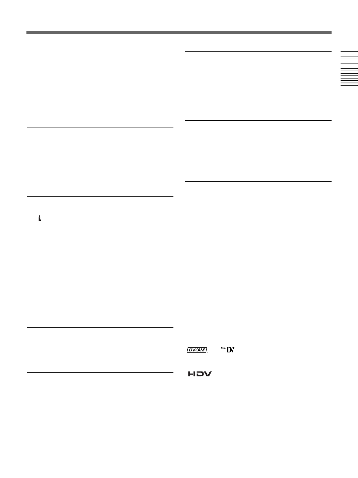
1 1 (on/standby) switch/ 1 (on/standby) lamp
Press this switch to turn the unit on. The 1 on/standby
lamp lights up in green.
2 Remote sensor
3 PHONE LEVEL control knob
Controls the volume of the headphones connected into
the PHONES jack 4.
4 PHONES jack
Connect stereo headphones for monitoring sounds
during the recording or playback. The audio signal you
want to monitor can be selected in [AUDIO MONI] on
the [AUDIO SET] menu. (p. 47)
5 LCD (Liquid Crystal Display) monitor
Displays the playback or EE
1)
pictures. Also,
superimposed time data, status information, menus,
audio level meters, etc. are displayed.
6 Operation panel
1 1 (on/standby) switch/
1 (on/standby) lamp
2 Remote sensor
3 PHONE LEVEL control knob
4 PHONES jack
5 LCD monitor
6 Operation panel
1 Indicator section
(see page 8)
2 Tape transport control
section
(see page 13)
........................................................................................................................................................................................................
1) “EE” stands for “Electric to Electric.” In EE mode, the video and audio signals input to the VCR’s recording circuitry do
not pass through any magnetic conversion circuits but output via electric circuits only. This mode is used to check the input
signals and adjust input levels. The pictures output in EE mode are referred to as EE pictures.
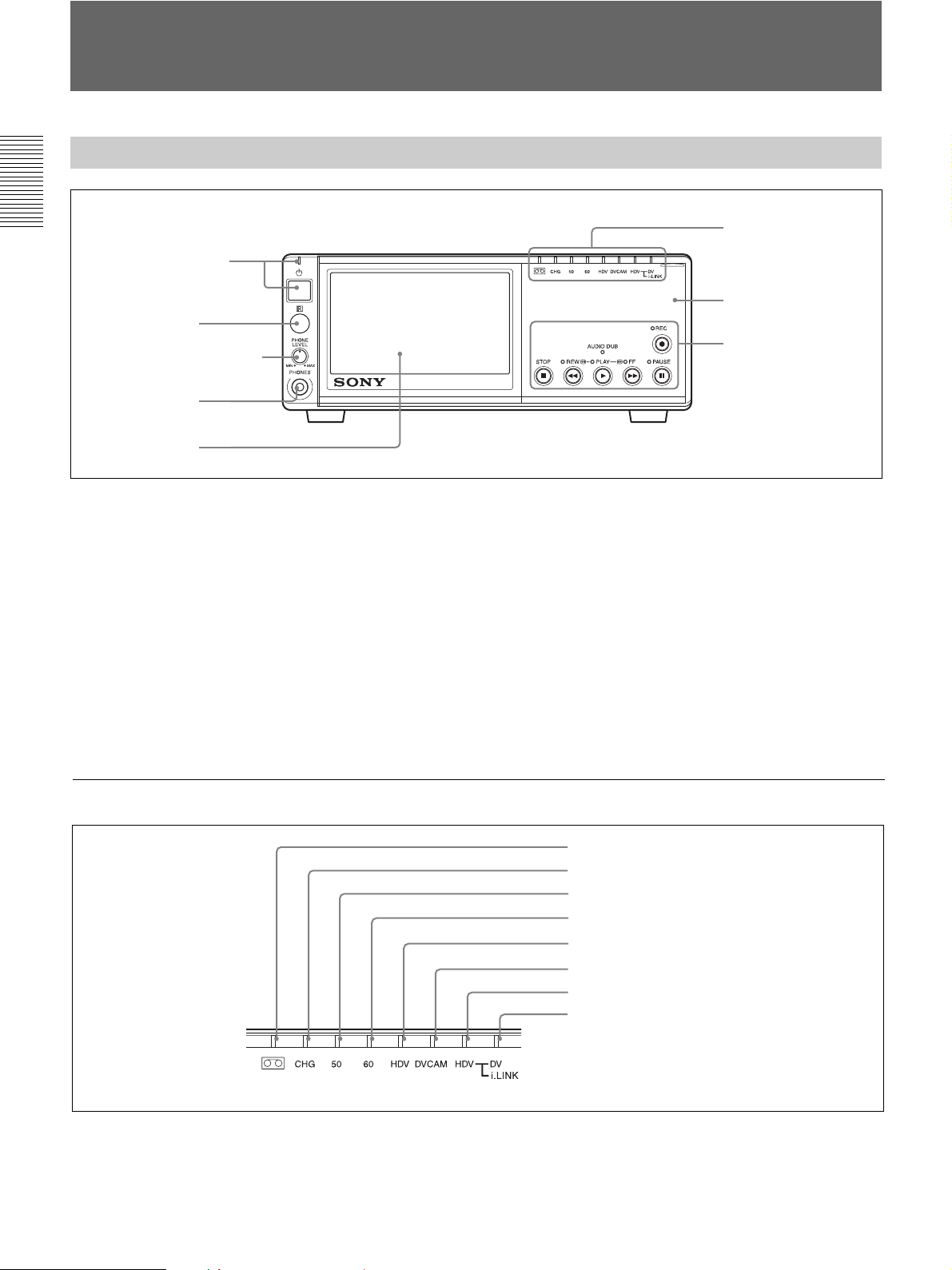
1 Indicator section
1 q (cassette) indicator
2 CHG (charge) indicator
3 50 indicator
4 60 indicator
5 HDV indicator
6 DVCAM indicator
7 HDV-i.LINK indicator
8 DV-i.LINK indicator

Chapter 1 Overview 9
Chapter 1 Overview
1 q (cassette) indicator
Lights up when a digital video cassette is loaded. Does
not light up while the cassette compartment opens or
the cassette is not loaded.
This indicator flashes while a cassette is being
removed.
For details, see “Inserting/Ejecting Cassettes” on page 22.
2 CHG (charge) indicator
Lights up while charging the battery pack (not
supplied) attached to the rear of the unit. When the 1
(on/standby) switch is standby and the battery pack is
attached, the unit will automatically enter charging
mode.
When the battery pack is fully charged, the indicator
turns off.
For details, see “Using the optional battery” on page 65.
3 50 indicator
Lights up when:
•During EE mode or recording when [50i/60i SEL] on
the [OTHERS] menu is set to 50i.
• 50i or PAL formatted video signals are input to the
HDV/DV jack.
•A tape that has 50i or PAL formatted video signals is
being played back.
4 60 indicator
Lights up when:
•During EE mode or recording when [50i/60i SEL] on
the [OTHERS] menu is set to 60i.
• 60i or NTSC formatted video signals are input to the
HDV/DV jack.
•A tape that has 60i or NTSC formatted video signals
is being played back.
5 HDV indicator
Lights up when the unit is in the following operating
status.
•When a tape recorded in the HDV format is being
played back.
•When HDV formatted video signals are input through
the i.LINK interface.
•When [VCR HDV/DV] on the [IN/OUT REC] menu
is set to [HDV].*
*This indicator lights up when there is no input signal,
[VCR HDV/DV] is set to [AUTO], and the immediately
preceding signal input was recorded in HDV format.
6 DVCAM indicator
Lights up when the unit is in the following operating
status.
•When a tape recorded in the DVCAM format is being
played back.
•When [ REC MODE] on the [IN/OUT REC] menu is
set to [DVCAM].
Note
Neither the HDV indicator nor the DVCAM indicator
lights up when a tape recorded in the DV format is
being played back.
7 HDV-i.LINK indicator
Lights up when HDV formatted video signals are
input/output through the i.LINK interface.
8 DV-i.LINK indicator
Lights up when DVCAM/DV (SP mode) formatted
signals are input/output through the i.LINK interface.
10 Chapter 1 Overview
Chapter 1 Overview
Section behind the Operation Panel
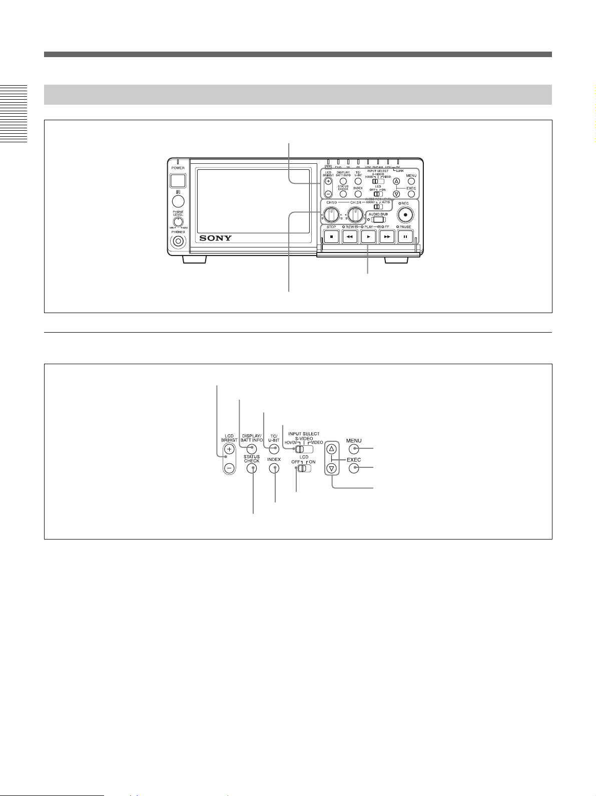
1 Upper control section
1 LCD BRIGHT (+/–) button
Adjust the brightness of the LCD panel.
+: Brightens.
–: Dims.
2 DISPLAY/BATT INFO button
Superimposes data items such as the time code upon
pictures.
If you keep pressing this button while the unit is turned
off and the battery pack is attached, charge level of the
battery pack and the remaining time that you can
playback will be displayed. (p. 65)
3 TC/U-BIT button
Displays time data. Every time you press this button
the time code or the user bits are displayed alternately.
(p. 40)
4 INPUT SELECT switch
You can select HDV/DV, S VIDEO, or VIDEO to
input signals.
The type of selected signal is displayed on the Data
screen on the LCD monitor on the front panel.
When HDV/DV is selected, input the signal you
selected in [VCR HDV/DV] on the [IN/OUT REC]
menu. (p. 48)
1 Upper control section
2 Audio control section
3 Tape transport control section
1 LCD BRIGHT button
2 DISPLAY/BATT INFO button
3 TC/U-BIT button
4 INPUT SELECT switch
5 STATUS CHECK button
6 INDEX button
7 LCD ON/OFF switch
8 MENU button
9 EXEC button
0 f/F button
Location and Function of Parts

Chapter 1 Overview 11
Chapter 1 Overview
Notes
• If you change this selector, the screen may
momentarily becomes bright or noise may appear.
This noise will be recorded.
•Do not change this switch setting during recording.
If you change the setting of this switch during
recording, the recorded image will be interrupted for
several seconds. Recording will restart after the
internal circuit is switched. During this time, no
image is recorded.
Also, the unit may mistakenly recognize a copyright
protected signals that has been input.
5 STATUS CHECK button
Press this button to check the audio setting and output
setting information (see page 20). When you press the
f/F button, you can switch the screens between audio
information and output information.
6 INDEX button
Press this button during recording to mark an index. If
you mark an index at the scene you want to search for,
you can easily find the scene later.
For details on index, see “Recording Functions” on page
34.
7 LCD ON/OFF switch
Press this switch to turn the LCD monitor ON and
OFF.
8 MENU button
Press this button to display the menus.
For details of the menu, see “Operating the Menus” on
page 45.
9 EXEC (execute) button
Press this button to change the setting on the menu
items.
0 f/F buttons
Press these buttons to move around in the menu or
status check items, or select the menu and items.
12 Chapter 1 Overview
Chapter 1 Overview
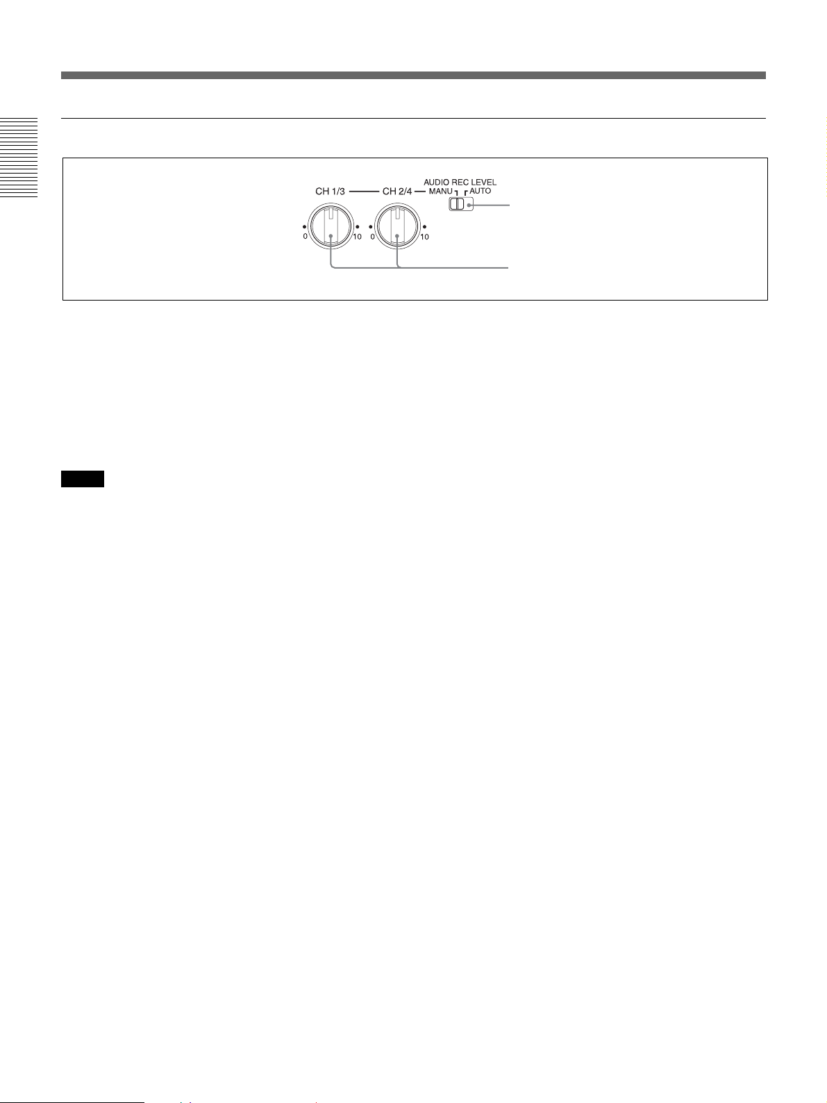
2 Audio control section
1 AUTO/MANU (manual) audio switch
Switches the audio recording level adjustment mode.
AUTO: The recording level is automatically
adjusted in accordance with an input audio.
MANU: Enables the AUDIO REC LEVEL control
knobs.
*When this switch is set to MANU, CH1/3 and CH2/4
control knobs are both set to manual mode.
Notes
•When i.LINK signals are input to the unit, the sound
recorded retains the signal level input, regardless of
the setting of this switch. You cannot adjust the audio
level with AUDIO REC LEVEL control knobs.
• If you input a sound whose level exceeds the
acceptable range, the recorded sound will be
distorted.
2 AUDIO REC LEVEL (VOL) (recording level
adjustment) control knobs
When intending to perform normal recording, by using
these knobs, adjust the levels of the analog audio
signals input to the unit (channel 1 and 2). When
intending to perform audio dubbing, using these knobs,
adjust the levels of channel 3 and 4.
These knobs are enabled only when the AUTO/MANU
(manual) audio switch is set to MANU.
1 AUTO/MANU (manual) audio switch
2 AUDIO REC LEVEL (VOL)
(recording level adjustment) control knobs
Location and Function of Parts
Chapter 1 Overview 13
Chapter 1 Overview
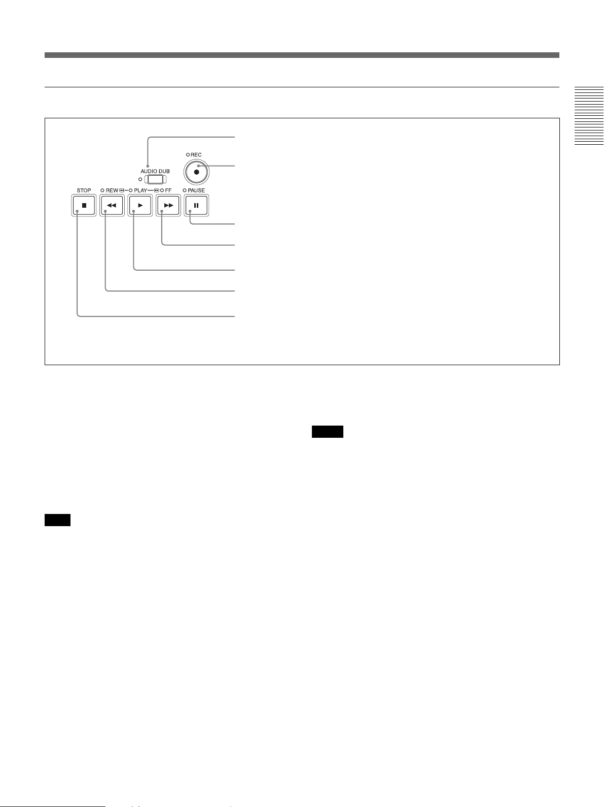
3 Tape transport control section
1 AUDIO DUB (audio dubbing) button/indicator
Use this button to dub sounds. The indicator lights up
while sounds are being dubbed.
For details on audio dubbing, see “Audio Dubbing” on
page 43.
2 REC (record) button/indicator
When you press the PLAY button while holding this
button down, the PLAY and REC indicators light up
and recording begins.
Note
You can record in the HDV/DVCAM and the DV
formats in SP mode.
LP mode is not supported.
3 PAUSE button/indicator
When you press this button during recording, playing,
or audio dubbing, the current operation goes into the
pause mode. Pressing this button again resumes the
operation. The indicator lights up while the unit is in
the pause mode.
4 FF (fast forward) button/indicator
When you press this button, the indicator lights up and
the tape is fast forwarded. During fast forward, the
picture does not appear on the monitor.
To locate a scene while monitoring the picture, hold
this button down during fast forward, playback or in
the playback pause mode.
5 PLAY button/indicator
When you press this button, the indicator lights and
playback begins.
Notes
• If the unit is playing a portion of a tape where the
recording formats are switched between HDV,
DVCAM, and DV or where the format of the system
signals are changed between 50i and 60i, the picture
and sound will be distorted on such a portion.
•You can play back a tape recorded in the HDV/
DVCAM/DV format in SP mode. LP mode is not
supported.
6 REW (rewind) button/indicator
When you press this button, the indicator lights and the
tape starts rewinding. During the rewind, the picture
does not appear on the monitor.
To locate a scene while monitoring the picture, hold
this button down during rewind, playback or in the
playback pause mode.
7 STOP button
Press this button to stop the current tape transport
operation.
1 AUDIO DUB (audio dubbing) button/indicator
2 REC (record) button/indicator
3 PAUSE button/indicator
4 FF (fast forward) button/indicator
5 PLAY button/indicator
6 REW (rewind) button/indicator
7 STOP button
Note: You can operate all buttons above except AUDIO
DUB with the operation panel closed.
14 Chapter 1 Overview
Chapter 1 Overview
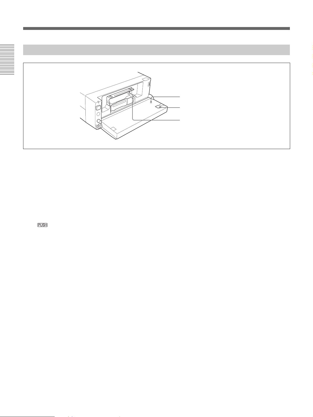
Inside of the Front Panel
1 RESET button
Press this button to clear all settings including the date
and time. Use the tip of a ball-point pen or similar tool
to press this button.
2 EJECT (cassette eject) button
Press this button to insert or remove a cassette. When
you press this button, the cassette tray comes up
automatically. Place the cassette in this tray and press
down
. After the cassette tray is retracted
automatically, close the front panel.
3 Cassette compartment
Insert a cassette.
For details of cassettes that can be used, see “Notes on
Power Supply and Video Cassettes” on page 21.
1 RESET button
2 EJECT button
3 Cassette compartment
Location and Function of Parts
Chapter 1 Overview 15
Chapter 1 Overview
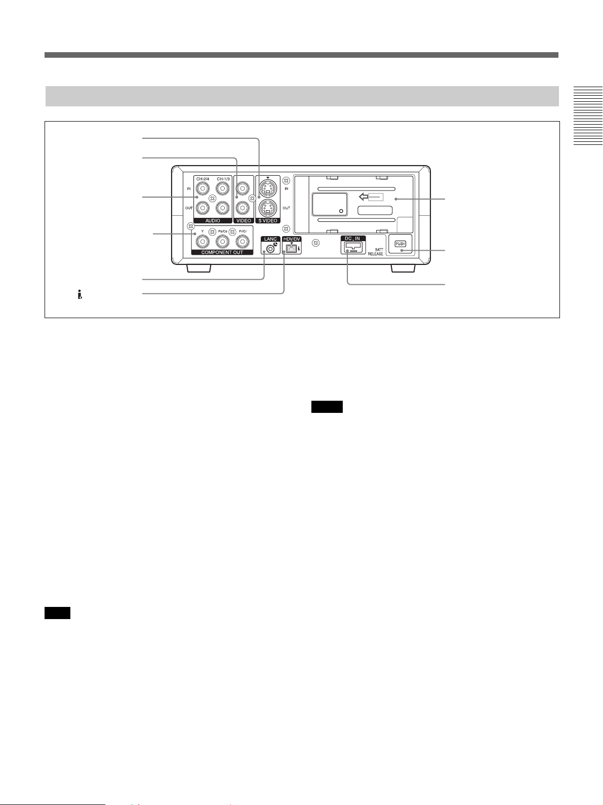
Rear Panel
1 S VIDEO jacks
To connect a device equipped with an S-video jack,
use the S VIDEO jack on the unit. If you use the S
VIDEO jack, you can input/output high-quality video
with less signal deterioration than the standard VIDEO
jack.
Text data such as the time code, menus, and alarm
messages are superimposed on an external monitor
connected to the S VIDEO jack (p. 19).
2 VIDEO jacks
Use to input and output analog video signals.
Text data is superimposed on a monitor in the same
way as a S VIDEO jack connection (p. 19).
3 AUDIO jacks
Use to input and output analog audio signals. During
normal recording, sounds are recorded onto channels 1
and 2. During audio dubbing, sounds are dubbed onto
channels 3 and 4.
Note
In the audio dubbing mode, the CH1/3 and CH2/4
jacks function as the channel 3 and channel 4 input
jacks, respectively.
4 COMPONENT OUT (output) jacks
Use to output component signals.
To connect a device equipped with the component
video input connector, use the COMPONENT OUT
jack on the unit. If you use the COMPONENT OUT
jack, you can output high-quality video with even less
signal deterioration than the S VIDEO jack.
1 S VIDEO jacks
2 VIDEO jacks
3 AUDIO jacks
4 COMPONENT OUT
jacks
5 LANC jack
6 HDV/DV jack
7 Battery terminal
8 BATT RELEASE button
9 DC IN jack
You can set the output video format by using
[COMPONENT] on the [IN/OUT REC] menu.
Text data is superimposed on a monitor in the same
way as a S VIDEO jack connection (p. 19).
Notes
• The output level of the COMPONENT OUT jack is
as follows:
Y: 1 Vp-p (480i NTSC/576i PAL: 0.3 V sync
negative)
Pb/Cb, Pr/Cr: 700 mVp-p (100% color bar), output
impedance 75 Ω (ohms)
You might need to change output signals. This
depends on the device you connect.
• The COMPONENT OUT jacks of this unit are
optimized for high-definition (HD) video output.
Therefore, the EE pictures of NTSC (480i) and PAL
(576i) are converted into simple video signals. When
you use EE pictures, note the following restrictions
on dubbing to another equipment and displaying on a
monitor television. These restrictions apply when
you output NTSC (480i) and PAL (576i) signals from
the COMPONENT OUT jacks.
– Since the effective display range of the luminance
signal and chrominance signal is different, a portion
consisting only of the chrominance signal exists in
the underscan video portion.
– Since the jitter (jitter of entire screen) of input
video signals is absorbed, the video signal is
forcibly reset in the underscan portion. You can
see this process in the underscan portion using an
underscan monitor.
(Continued)

16 Chapter 1 Overview
Chapter 1 Overview
– The output level of the luminance signal is different
from the specified value.
The above symptom is not a malfunction. This
condition will not affect images to be recorded on a
tape.The specified video signals are output from the S
VIDEO or VIDEO OUT jacks even in EE mode.
When you use this unit to input HDV signals from
the i.LINK jack and down-convert them to NTSC
(480i) or PAL (576i) signals, the specified video
signals are output.
• If you want to output video signals to the VIDEO, S
VIDEO, or COMPONENT OUT jack without text
data, select the [OTHERS] menu, [DISP OUTPUT],
then [LCD PANEL] (default setting). Or press the
DISPLAY/BATT INFO button on the unit, the
DATA CODE and SEARCH SELECT button on the
Remote Commander to clear the text data on the
monitor screen depending on the displayed items.
•During EE mode or recording, the subcarrier of the
color signal to be output from this unit is not
synchronized with the horizontal sync signal. The
color of the picture or the horizontal sync signal may
be distorted depending on the type of monitor
connected to the unit.
• The unit only can accept standard video signals.
If you input the types of video signals shown below,
recorded picture and sound may be distorted.
– Signals from some home game machines
–Blue background screen or gray background screen
from a consumer VCR
– Pictures played at a speed other than normal by a
VCR that does not have the TBC (Time Base
Corrector)
–Video signals in which the sync signals are
distorted
– Signals from a defective cassette (tape or recording
condition is bad) played by an analog VCR that
does not have TBC
5 LANC jack
Use when controlling the tape transport operation of
the unit using a device that has a LANC
1)
jack.
Notes
• The LANC jack on the unit has only LANC-S
functions. The unit has no LANC-M functions. A
device that is set to LANC-S mode cannot be
connected to this unit. Either this, the unit or the other
device may not operate properly.
• If the device you connect to this unit has a SHUTTLE
A/B switching function and a LANC-M function, set
the device to the SHUTTLE A mode for processing
HDV signals and set it to the SHUTTLE B mode for
processing DVCAM/DV (SP mode) signals.
• The LANC connection transmits signals such as
control signals, time code, time counter data, and
status data.
• Jacks labeled CONTROL L have the same function
as LANC jacks.
•When using this unit as a player, set the LANC mode
on the recorder to M. A device that does not have an
M / S switching function cannot be used to control
this unit.
•You cannot use LANC to perform power control.
•You may have some difficulties when you edit using
an HDV formatted tape.
Refer to the “Notes” in “Editing (Connecting with a
Personal Computer)” on page 39.
6 HDV/DV jack (4-pin)
Used to input/output the digital signal that complies
with the i.LINK standard. Use when a device
connected to the unit has an i.LINK jack. If you
connect the unit and another device using
HDV/DV
jacks, you can minimize deterioration of picture
quality during recording, dubbing, or capturing still
pictures, all by means of digital signal processing. For
details, refer to the instruction manual of the external
device.
Note
This jack can accept only HDV/DV/DVCAM signals.
For details , see “About i.LINK” on page 72.
7 Battery terminal
For details on batteries, see “Preparing the Power Supply”
on page 22.
8 BATT RELEASE (battery release) button
Press this button to eject and remove a battery.
9 DC IN jack
Connects to an AC outlet using the supplied AC
adaptor and power cord.
........................................................................................................................................................................................................
1) LANC (Local Application Control bus system):
Bidirectional interface used to control a consumer VCR
Location and Function of Parts
Chapter 1 Overview 17
Chapter 1 Overview
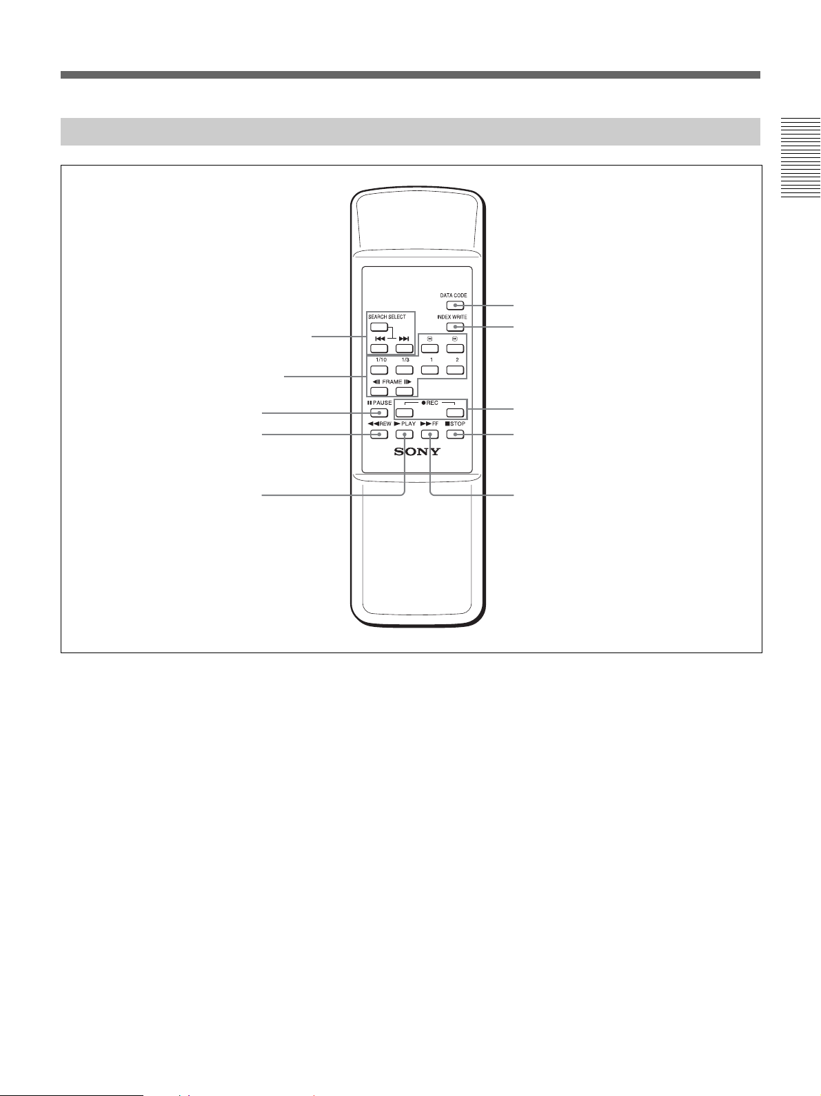
Supplied Remote Commander
1 SEARCH SELECT buttons
Press these buttons to search for scenes using the
search function.
For details on the search function, see “Searching using the
search function” on page 30.
2 Buttons for playing at various speeds
You can play back a tape at normal speed or at a speed
other than normal with these buttons.
For details, see “Playing at various speeds” on page 28.
3 PAUSE button
4 REW (rewind) button
5 PLAY button
××××
1 SEARCH SELECT buttons
2 Buttons for playing at
various speeds
3 PAUSE button
4 REW button
5 PLAY button
6 DATA CODE button
7 INDEX WRITE button
8 REC buttons
9 STOP button
0 FF button
6 DATA CODE button
Press this button to display the data codes (recording
date/time, camera data).
For details on data codes, see “Displaying information
(data codes) recorded on a tape” on page 27.
7 INDEX WRITE button
Press this button during the recording to mark an
index.
For details on an index, see “Marking an index” on page
34.
8 REC (record) buttons
When you press both these buttons at the same time,
the REC indicator and PLAY indicator on the front
panel light and recording begins.
9 STOP button
0 FF (fast forward) button
(Continued)
18 Chapter 1 Overview
Chapter 1 Overview
Notes
• The command mode of the supplied Remote
commander is set to VTR4. You cannot change this
setting.
• Set [REMOTE CTRL] on the [OTHERS] menu to
[ON] to enable the Remote Commander to control the
unit.
• In addition to the Remote Commander supplied with
the unit, the unit accepts signals from any Sony
Remote Commander whose command mode is set to
VTR4. If you want to disable the control from any
Remote Commander, set [REMOTE CTRL] on the
[OTHERS] menu to [OFF].
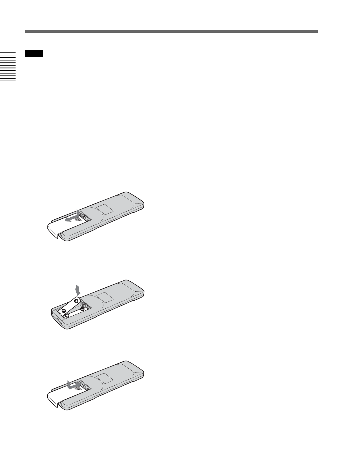
Battery installation
1 Push and slide the lid to open.
2 Install two size AA (R6) batteries (supplied) with
the correct polarity.
3 Replace the lid.
Be sure to install the
battery from the # side.
Notes on batteries
• Make sure that the battery orientation is correct when
inserting batteries.
• Do not mix an old battery with a new one, or mix
different types of batteries.
• If you do not intend to use the Remote Commander
for a long time, remove the batteries to avoid damage
from battery leakage. If the batteries have leaked,
remove them, wipe the battery compartment dry and
replace the batteries with new ones.
To remove the batteries
Remove the lid as step 1 and take out the batteries.
Location and Function of Parts
Chapter 1 Overview 19
Chapter 1 Overview
Displaying Various Data
This unit can display various superimposed text data
on the built-in LCD monitor and also an external
monitor connected to the unit. To display text data on
an external monitor, set [DISP OUTPUT] on the
[OTHERS] menu to [V-OUT/PANEL]. You can turn
ON/OFF various text data display by pressing the
DISPLAY/BATT INFO button.
Menu screen
Press the MENU button to display the menu screen.
You can change or confirm the menu item settings on
this screen.
For details on the menu, see “Chapter 4 Adjusting and
Setting Through Menus” on page 45.
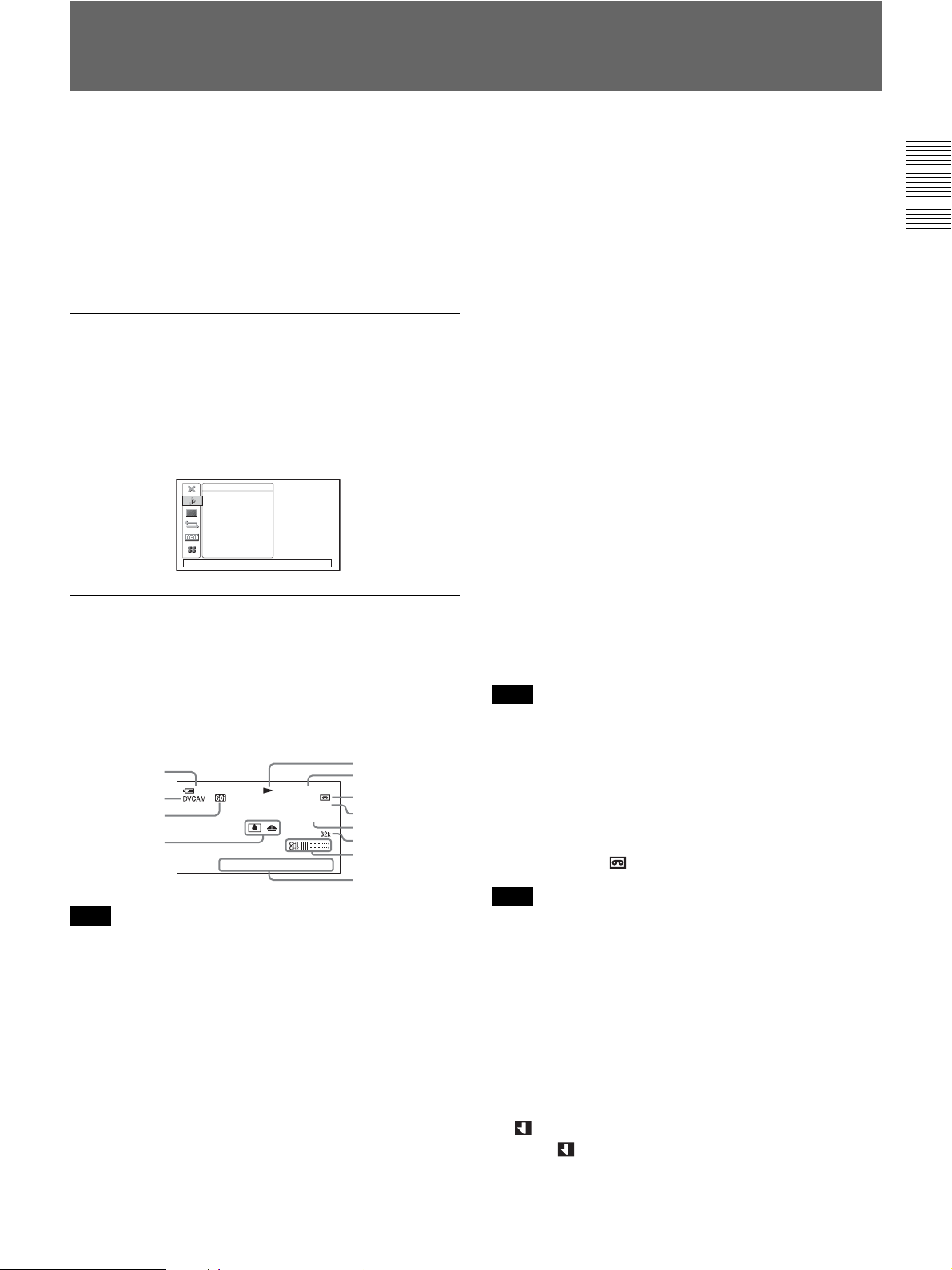
Data screen
You can display the data screen by pressing the
DISPLAY/BATT INFO button when the unit is turned
on. You can confirm important information for normal
recording or playback, such as time code or remaining
tape time, on the screen.
Note
The text data superimposed on an external monitor
connected to the VIDEO, S VIDEO, or COMPONENT
OUT jack is the same as those superimposed on the
LCD monitor. If you set [COMPONENT] on the [IN/
OUT REC] menu to [1080i/480i]* for the output from
COMPONENT OUT jack during HDV playback, only
the tape transport mode indicator and time counter are
displayed as text data.
* When [50i/60i SEL] is set to 60i. This setting value is
[1080i/576i] when [50i/60i SEL] is set to 50i.
AUDI O SET
AUDIO MONI
AUDI O MIX
AUDIO MODE
AUDIO LOCK
AUDI O LIMIT
[
MENU
]
: END
120min
00:12:34:12
60min
HDV/DV
IN
INDEX 00
SEARCH
AWB18018
dB
F1.6
1
2
3
5
6
7
8,9
0
qs
qd
1 Remaining battery
When you use this unit with a battery, the battery
remaining time is displayed. This information may not
be displayed correctly depending on the operating
status and the environment.
2 Format indicator
[HDV1080i], [DVCAM], or [DV SP] are displayed.
3 50i/60i indicator
4 Alarm indicator
Displays an alarm indicator.
For details on alarm indicators, see “Warning indicators
and messages” on page 59.
5 Tape transport mode indicator
Displays the tape transport mode.
6 Time code or user bits indicator
Every time you press the TC/U-BIT button, the time
code or user bits are displayed alternately.
TC : [00:00:00:00] or [00:00.00:00]
In the drop frame mode, a period (.) is displayed
between the minute value and second value.
U-BIT : [00 00 00 00]
Note
When you playback a tape without setting a time code
or user bit record, or without seting a time code
recorded in different formats, the unit cannot display
them correctly.
7 Remaining tape time indicator
Displays the remaining tape time.
For details, see “[ REMAINING]” on page 52.
Note
When you insert a cassette in which the tape has been
rewound to the beginning, this indicator will not show
the remaining tape time. The remaining tape time is
displayed after the tape runs for a while.
8 INPUT SELECT indicator
Changes according to the position of the INPUT
SELECT switch. ([HDV/DV IN], [S VIDEO IN] or
[VIDEO IN])
9
(Index) indicator
Displays
when an index has been marked.
4
qa
(Continued)
20 Chapter 1 Overview
Chapter 1 Overview
0 Search indicator
Displays the search mode when you search for scenes
using the Remote Commander.
For details on the search function, see “Searching using the
search function” on page 30.
qa Audio mode indicator
In the recording mode, displays
when you select
[FS32K] for [AUDIO MODE] on the [AUDIO SET]
menu. When you select [FS48K],
is displayed.
During playback or audio dubbing, displays the audio
mode recorded on the tape. During the i.LINK input,
displays the audio mode of the signal input to
HDV/
DV jack.
Notes
• The audio mode will not be displayed when [VCR
HDV/DV] on the [IN/OUT REC] menu is set to
[HDV].
• Signals other than the HDV/DVCAM lock mode will
become non-standard audio and
/ is
displayed during playback or when the signal is input
from the
HDV/DV jack.
qs Audio level meters
They are displayed when the AUTO/MANU audio
switch is set to MANU.
Notes
• The audio level meters will not be displayed when the
INPUT SELECT switch is set to HDV/DV.
•When [AUDIO MIX] is set to [CH3, CH4] in the
[AUDIO SET] menu, the audio level meters will
display CH3 on the CH1 indicator and CH4 on the
CH2 indicator.
qd Date/time and camera data indicator
When you press the DATA CODE button of the
Remote Commander, you can switch the display
between recording date/time and camera data.
For details on the date/time and camera data indicator, see
“Displaying information (data codes) recorded on a tape”
on page 27.
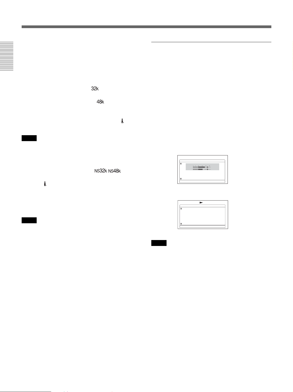
STATUS CHECK screen
You can confirm the setting values of the following
items by pressing the STATUS CHECK button.
•[AUDIO] settings such as [AUDIO MONI] and
[AUDIO MIX]
•[OUTPUT] settings such as [VCR HDV/DV],
[COMPONENT], [i.LINK CONV] and [DOWN
CONVERT]
Every time you press the f/F button, you can switch
the display between audio-related settings and output-
related settings.
Press the STATUS CHECK button again to make the
status check screen off.
[AUDIO] screen
[OUTPUT] screen
Notes
• The information items displayed on the [AUDIO]
screen during playback on this unit are different from
those displayed while video signals are input through
the i.LINK interface.
• The audio level meters will display the output signal
level during playback and input signal level during
recording.
•When [AUDIO MIX] is set to [CH3, CH4] in the
[AUDIO SET] menu, the audio level meters will
display CH3 on the CH1 indicator and CH4 on the
CH2 indicator.
0:00:00:00
AUDI O
INPUT : HDV/DV
AUDIO MONI : CH1, CH2
AUDIO MIX : CH1, CH2
[
STATUS CHECK
]
: END
1/2
30 20 10 040-∞
CH1
CH2
0:00:00:00
OUTPUT
VCR HDV/DV : AUTO
COMPONENT : 1080i/480i
i.LINK CONV : OFF
LOCK MODE
DOWN CONVERT : LETTER BOX
[
STATUS CHECK
]
: END
2/2
Displaying Various Data
Chapter 2 Playback and Recording 21
Chapter 2 Playback and Recording
Chapter2
Playback and
Recording
Notes on Power Supply and Video Cassettes
Usable cassettes
We recommend you to use a digital master cassette
(PHDVM-63DM) and a Mini-DV/DVCAM cassette
for recording in the HDV/DV format.
We recommend you to use a Mini-DVCAM cassette,
or digital master cassette (PHDVM-63DM) for
recording in the DVCAM format.
Cassette memory
Some Mini-DV and Mini-DVCAM cassettes have the
cassette memory
mark. This unit, however, does
not support cassette memory.
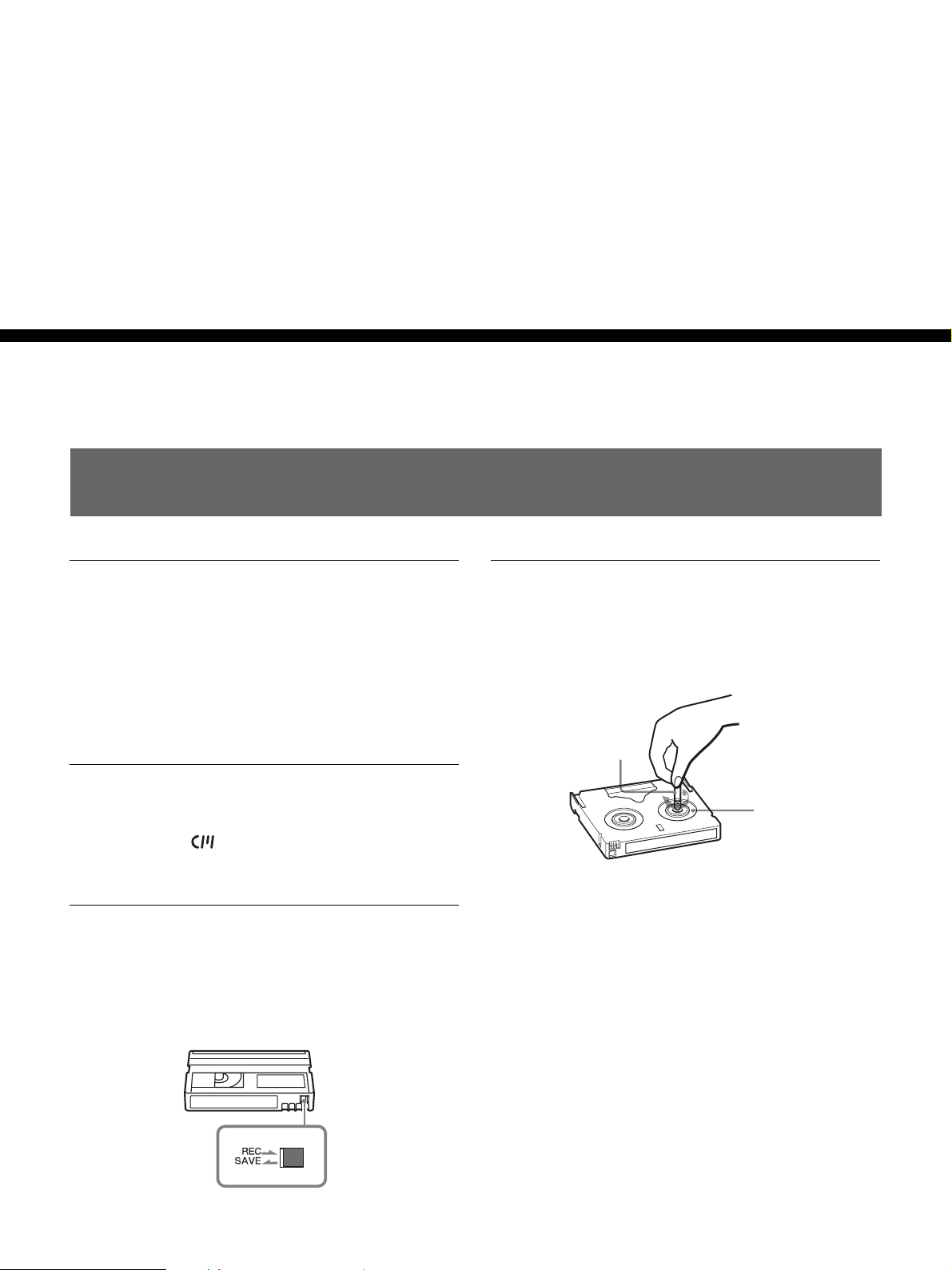
To save a recording
To prevent accidental erasure of a recording, slide in
the REC/SAVE switch on the cassette so that the red
portion becomes visible. To record on a tape, slide out
the switch so that the red portion is hidden.
REC/SAVE switch
Set to SAVE.
Checking the tape for slack
Using a paper clip or a similar object, turn the reel
gently in the direction shown by the arrow. If the reel
does not move, there is no slack.
Paper clip, etc.
Reel
22 Chapter 2 Playback and Recording
Chapter 2 Playback and Recording
Preparing the Power Supply
Connect the power cord (supplied) to the AC adaptor
and the DC plug of the AC adaptor to the DC IN jack
on this unit. Next, connect the power plug to an AC
outlet. When you disconnect the power cord, be sure
to unplug the power cord from the AC outlet first.
PRECAUTION
Even if this unit is turned off, AC power (house
current) is still supplied to it while connected to the
wall outlet via the AC adapter.
Notes
•Never short-circuit the DC plug of the AC adaptor or
battery terminal with a metal object. A short circuit
can damage the unit.
•Use a nearby wall outlet when using the AC Adaptor.
Disconnect the AC Adaptor from the wall outlet
immediately if any malfunction occurs.
•Do not use the AC Adaptor placed in a narrow space,
such as between a wall and furniture.
The [CLOCK SET] screen appears when you turn on
the unit for the first time.
Refer to page 52 on how to set the date and time.
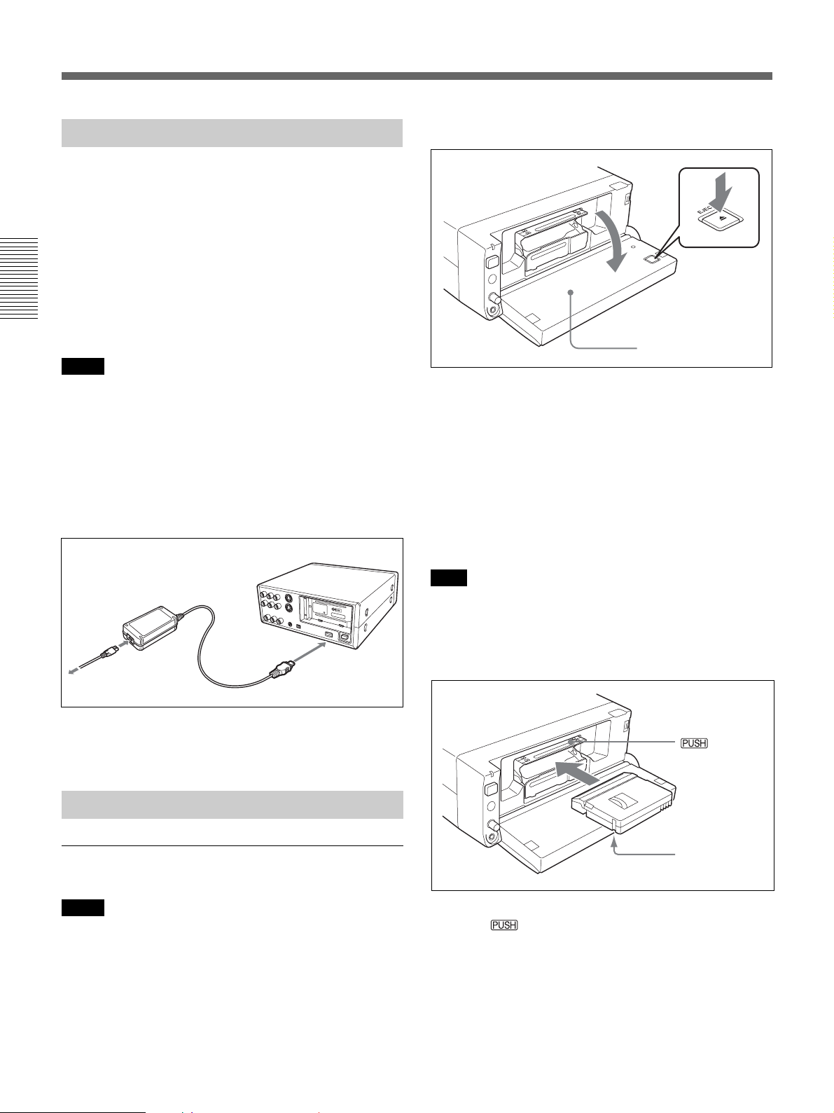
Inserting/Ejecting Cassettes
To insert a cassette
Notes
•Do not insert the cassette forcibly. The unit may be
damaged.
•Do not eject/load the cassette in a place subject to
light. The internal sensor of the unit may operate
incorrectly if too much light falls on the unit.
1 Open the front panel.
2 Press the EJECT button while the AC adaptor or
battery is attached to the unit.
The cassette tray will come out automatically.
3 After checking the tape for slack, hold the cassette
so that the tape window is facing upward, then
insert it into the unit.
Note
If the cassette does not load or is loaded only halfway,
eject it once, then insert it again. In such a case, if you
insert the cassette forcibly, the cassette may not be
loaded properly or malfunctions may occur.
4 Press .
After the cassette tray is automatically retracted,
close the front panel. Confirm that the q
(cassette) indicator is lit.
EJECT button
Front panel
q (cassette)
indicator
Notes on Power Supply and Video Cassettes

Chapter 2 Playback and Recording 23
Chapter 2 Playback and Recording
Removing the cassette
1 Open the front panel.
2 Press the EJECT button while the AC adaptor or
battery is attached to the unit.
The cassette tray will come out automatically.
3 Remove the cassette and press .
The cassette tray is automatically retracted.
4 Close the front panel.
Notes on Playback/Recording
No compensation for contents of the
recording
Contents of the recording cannot be compensated for if
recording or playback is not successful due to a
malfunction of the unit, video tape, etc.
Copyright precautions
Television programs, films, video tapes, and other
materials may be copyrighted. Unauthorized recording
of such materials may be contrary to the copyright
laws.
On recording
You cannot record any software having copyright
protection signals on this unit. If you start recording
protected video and audio signals, a warning appears
on the monitor screen and the unit stops recording.
During recording, do not change the INPUT SELECT
switch setting. If you do so, the unit may mistakenly
recognize that a copyright control signal has been
input.
On playback
When you play back software having copyright
protected signals on this unit, you may not be able to
copy it onto other equipment.
Limitations caused by differences in format
The unit can record and play back tapes recorded in
HDV1080i/DVCAM format. It can also record and
play back tapes recorded in DV format (SP mode).
However, due to differences in format, you may not be
able to play back or edit some tapes affected by
recording conditions of the tape (e.g., a tape originally
recorded in DV format is dubbed in DVCAM format).
You can play back for HDV 720/30p format, while
you cannot output the video signals from
HDV/DV
jack.
For details, see “Compatibility of HDV, DVCAM and DV
Format” on page 68.
If a tape has both a portion recorded in the HDV/
DVCAM format and one recorded in the DV format
(SP mode), the following limitations are applied when
you play back the tape with this unit:
• The image may be distorted and noise may occur at
the point where the recording format changes on the
tape.
• The tape transport control buttons may be disabled
until the tape speed is stabilized.
Note on playback on other equipment
A tape recorded in the HDV format cannot be played
back with the devices not compatible with the HDV
1080i format. We recommend confirming the contents
of the tape by playing back the tape before playing
back it on another video equipment.
 Loading...