


Cinema Processor System
DIGITAL FILM SOUND DECODER
DFP-D3000
DIGITAL FILM SOUND READER
DFP-R3000
®
QUICK START GUIDE 1st Edition (Revised 1)
Table of Contents
Check List ........................................................................................................... |
3 |
|
1. |
Introduction ............................................................................................ |
1-1 |
2. |
Equipment and accessories ............................................... |
2-1 |
3. |
Basic checks of site and installation ...................................... |
3-1 |
4. |
Checks of correct DFP-R3000 Reader mounting ............ |
4-1 |
5. |
A-Chain alignment using DFP-D3000 front panel |
|
|
controls ..................................................................................................... |
5-1 |
6. |
B-Chain Alignment ............................................................................. |
6-1 |
7. |
Overall systems check and listening test ............................ |
7-1 |
8. |
Troubleshooting .................................................................................. |
8-1 |
9. |
Appendix .................................................................................................. |
9-1 |
9.1 DFP-D3000 Rear Panel Connector Pin Assignment ................................... |
9-1 |
|
9.2 |
DFP-D3000 Input/Output Level ................................................................. |
9-4 |
9.3 |
Changeover Settings .................................................................................... |
9-5 |
9.4 Settings for using DFP-D3000 as DFP-D2000 ........................................... |
9-6 |
|
|
9.4.1 Conditions .................................................................................. |
9-6 |
9.4.2Connections and Settings When Connecting to the Output
of the Existing System ............................................................... |
9-6 |
9.4.3Connections and Settings When Connecting to the Input
of the Existing System ............................................................... |
9-9 |
9.5 Description on Connection of DA-20 and DFP-D3000 ............................ |
9-12 |
9.5.1 Outline of System ..................................................................... |
9-12 |
9.5.2 Requirements at SDDS Side .................................................... |
9-12 |
9.5.3 Connections of the DA-20 and Setting the Operation Mode ... |
9-12 |
9.5.4 Connections for Using AUX1 Input ........................................ |
9-13 |
9.5.5 Connections for Using AUX2 Input ........................................ |
9-15 |
9.5.6 Audio Connecting the DA-20 and DFP-D3000 ....................... |
9-17 |
9.6 Connecting the CP-500 and DFP-3000 ..................................................... |
9-18 |
9.6.1 Connecting the DFP-D3000 to the CP-500 with |
|
the DFP-D3000 as master ........................................................ |
9-18 |
9.6.2 Connecting the DFP-3000 to the CP-500 with |
|
the CP-500 as master ................................................................ |
9-23 |
DFP-3000 |
1 |
9.7 Connecting the DTS-6, DTS-6D and DFP-D3000 ................................... |
9-26 |
|
9.7.1 |
Outline of System ..................................................................... |
9-26 |
9.7.2 |
Requirements of SDDS Side .................................................... |
9-26 |
9.7.3 |
Connecting the DTS Processor DTS-6 .................................... |
9-26 |
9.7.4 |
Connection of Control Signals from DTS Processor DTS-6D .... |
9-31 |
9.7.5 |
Audio Connecting the DTS-6, DTS-6D and DFP-D3000 ....... |
9-36 |
9.8 Corresponding to DFP-D3000 Surround EX ............................................ |
9-37 |
|
9.8.1 |
Restrictions on Control of Surround EX Decoder ................... |
9-37 |
9.8.2 |
Connections of Audio System .................................................. |
9-37 |
9.8.3 |
Actual Connection of Control System ..................................... |
9-39 |
9.8.4 |
SA-10 Operations When Controlling from the DFP-D3000 .... |
9-40 |
9.8.5 |
Controlling Surround EX from DA-20 .................................... |
9-41 |
9.8.6 |
Controlling Surround EX from DTS-6 or DTS-6D ................. |
9-43 |
9.8.7 |
Controlling Surround EX control |
|
|
from Automation Controller .................................................... |
9-43 |
9.8.8 |
Adjustments of Audio System ................................................. |
9-44 |
9.9 Test Cable for Performing A-Chain Adjustment ...................................... |
9-51 |
|
9.10 Adjusting the Analog Track Pickup .......................................................... |
9-52 |
|
9.10.1 |
Preliminary Preparations Before Adjustments ......................... |
9-52 |
9.10.2 |
Lateral Film Guide Adjustment ............................................... |
9-52 |
9.10.3 |
Lateral Exciter Lamp Adjustment ............................................ |
9-52 |
9.10.4 |
Lateral Solar Cell Adjustment .................................................. |
9-52 |
9.10.5 |
Vertical Adjustment of Exciter Lamp ...................................... |
9-53 |
9.10.6 |
Slit Lens Adjustment ................................................................ |
9-53 |
9.10.7 |
Double Checking of Illumination Inconsistency ...................... |
9-53 |
9.10.8 |
Wiring Check ........................................................................... |
9-53 |
9.11 Description of the DFP-D3000 Setup Software Menus ............................ |
9-54 |
|
9.11.1 |
Start-up Screen ......................................................................... |
9-54 |
9.11.2 |
Description of File Menu Items ............................................... |
9-56 |
9.11.3 |
Description of Config Menu Items .......................................... |
9-57 |
9.11.4 |
Description of Preset Menu Items ............................................ |
9-58 |
9.11.5 |
Description of A-Chain Menu Items ........................................ |
9-59 |
9.11.6 |
Description of Tools Menu Items ............................................ |
9-60 |
9.11.7 |
Description of Master Menu Items .......................................... |
9-61 |
9.11.8 |
Description of Test Menu Items ............................................... |
9-62 |
9.11.9 |
Description of Help Menu Items .............................................. |
9-63 |
n
SDDS is a registered trademark of Sony Corporation.
DTS, DTS ES and DTS Extended Surround are trademarks or registered trademarks of Digital Theater Systems, Inc.
Dolby, Dolby Digital and Dolby Surround are trademarks or registered trademarks of Dolby Laboratories Licensing Corporation.
Unless otherwise specified, all name of companies and products are trademarks or registered trademarks of the respective companies.
2 |
DFP-3000 |
Check list
This is a step by step check list for the experienced installer. Refer to the associated sections of this Guide for additional information and see the Tech Notes for specific details.
|
|
|
Page |
1. |
Read about the advanced features of the DFP-3000 Player System. .......... |
1-1 |
|
2. |
Check that you have all necessary components and equipment. ................ |
2-1 |
|
|
2.1 |
Components included with the DFP-D3000 Decoder. .................... |
2-1 |
|
2.2 |
Components included with the DFP-R3000 Reader. ....................... |
2-1 |
|
2.3 |
Additional equipment available from Sony. .................................... |
2-1 |
|
2.4 |
Personal equipment you will need. .................................................. |
2-1 |
3. |
Perform basic checks of the Decoder. ......................................................... |
3-1 |
|
|
3.1 |
Ensure that the Decoder’s installed environment is acceptable. ...... |
3-1 |
|
3.2 |
Connect the Reader to the Decoder, turn on mains power, |
|
|
|
and confirm activity. ........................................................................ |
3-1 |
|
|
Caution! Do not hot-plug the Reader! |
|
|
3.3 |
Confirm that the Decoder firmware is version 2.74 or later. ........... |
3-1 |
3.4Confirm that the Setup Software on your laptop is version 2.00 build 2.055 or later. Check Tech Note TN99121401
for the latest version. ........................................................................ |
3-2 |
3.5 Confirm a solid earth ground for the Decoder chassis. .................... |
3-2 |
3.6Be sure that the optical input connector is wired correctly-
|
it’s not the same as others’. .............................................................. |
3-2 |
|
3.7 Confirm that the interface wiring has been done properly. |
|
|
The Appendices and Tech Notes offer details on specific |
|
|
installation issues. ............................................................................... |
3-2 |
4. |
Confirm that the Reader is mounted correctly on the projector. ................. |
4-1 |
4.1Confirm the correct installation for your projector according
|
|
to the DFP-R3000 Installation Guide that comes with the Reader. ..... |
4-1 |
|
4.2 |
Be sure you have at least 32 frames between the Reader LEDs |
|
|
|
and the gate. ....................................................................................... |
4-1 |
|
4.3 |
Make sure the film path is not twisted or misaligned. ..................... |
4-1 |
5. |
Align the A-Chain. ...................................................................................... |
5-1 |
|
|
5.1 |
Align and clean the solar cell and optics. See Tech Note |
|
|
|
99111901 for details. ............................................................................ |
5-1 |
5.2Connect your test cable, X-Y oscilloscope, and real time analyzer (RTA) to the front panel Headphone jack
(see Tech Note TN99101201 for instructions on making this cable). Use Monitor Select position 1.
|
Use the Decoder’s front panel facilities to perform A-Chain calibration. .. |
5-1 |
5.3 |
Go to the Config menu and enter the default password “SONY”. ...... |
5-1 |
5.4 |
Play a tone loop and trim the gain for projector 1 (OPT1) |
|
|
L and R inputs. |
|
|
Block the slit slowly and confirm that R drops before L. ................. |
5-3 |
DFP-3000 |
3 |
|
|
|
Page |
|
5.5 |
Play a B&W pink noise loop and set the slit loss EQ frequency |
|
|
|
for L and R. |
|
|
|
Repeat 5.4, 5.5, and 5.6 for the second projector of a |
|
|
|
changeover installation. ....................................................................... |
5-4 |
6. |
Align the B-Chain. ...................................................................................... |
6-1 |
|
|
6.1 |
Connect your laptop to the Decoder’s RS232 port with |
|
|
|
a null-modem serial cable, launch the Setup Software, |
|
|
|
and “connect” the Software to the Decoder. .................................... |
6-1 |
|
6.2 |
Open the Master DFP-3000 screen and set the Master |
|
|
|
Volume to 0.0 dB and set the -20 dBFS output level |
|
|
|
reference to -10 dBu. ....................................................................... |
6-1 |
|
6.3 |
Zero out the Software on the main screen, link Mutes to |
|
|
|
Selects, and bring up the Test Signal screen. ................................... |
6-1 |
|
6.4 |
Select pink noise; select All On; use PC function keys |
|
|
|
to select output channels. ................................................................. |
6-2 |
|
6.5 |
Check that noise is coming from the selected non-sub |
|
|
|
channel at about 85 dB SPL, or 82 dB for the L and R |
|
|
|
surround speakers. ........................................................................... |
6-3 |
|
6.6 |
Use your RTA and each non-sub channel’s graphic EQ |
|
|
|
to dial in the X-curve for each speaker except the subwoofer. ........ |
6-3 |
|
6.7 |
Adjust each screen speaker to exactly 85 dB SPL and the |
|
|
|
surrounds to 82 dB SPL. .................................................................. |
6-3 |
6.8Set the subwoofer channel’s parametric EQ for
smooth response ; set each preset’s subwoofer low pass filter
to 100 Hz or lower except SDDS, which should be higher. ............ |
6-4 |
6.9Referring to your RTA, set the level of the analog subwoofer so that its bands are about the same level as the center
speaker’s bands in its flat response region. ...................................... |
6-4 |
6.10Again referring to your RTA, set the level of the digital (SDDS) subwoofer bands to 10 dB higher than the flat bands of the center
|
|
speaker. ............................................................................................ |
6-5 |
|
6.11 |
Set the surround channel delay for each appropriate Preset. ........... |
6-6 |
|
6.12 |
Set AUX inputs’ subwoofer levels to +10 dB, if other digital |
|
|
|
systems are installed. ....................................................................... |
6-6 |
|
|
|
Page |
|
6.13 |
Adjust the sync between optical tracks and SDDS. ......................... |
6-7 |
|
6.14 |
Configure your presets for names, output matrix, and fallback. ...... |
6-7 |
|
6.15 |
Match levels between presets using the trims; set bypass levels; |
|
|
|
set HI levels. .................................................................................. |
6-10 |
7. |
Perform an overall systems checkout and listening test. ............................ |
7-1 |
|
8.Refer to the Troubleshooting section for help with problems
|
you encounter. ............................................................................................. |
8-1 |
9. |
Appendix with connector pinout charts. .................................................... |
9-1 |
4 |
DFP-3000 |
1.Introduction
The Sony DFP-3000 Cinema Processor forms the heart of the projection booth sound system in your theatre. It provide a sophisticated system for playing SDDS digital sound tracks, high quality optical soundtrack playback, comprehensive B-Chain control, and many other features. Here are just a few:
.The DFP-3000 system of projector-mounted reader and rack-mounted decoder perform traditional audio processing entirely in the digital domain. Inputs are processed with 20-bit A/D converters and then slit-loss EQ, noise reduction, and matrix decoding are all processed and adjusted digitally. After B- chain processing, fully balanced outputs are driven by 20-bit D/A converters.
.A comprehensive fallback system with two auxiliary inputs permits automatic playback of all three digital sound systems (by connecting the analog outputs of the other digital decoders into the AUX inputs of the DFP-D3000) as well as optical and non-sync inputs. You can select an AUX input to play in the event there is no SDDS digital soundtrack, a second auxiliary input to play if the first has no
valid audio, and optical to play automatically if no digital soundtrack of any kind is available.
.The B-Chain system of the DFP-3000 is exceptionally flexible. It provides seven channels of multiband graphic equalization, surround delays, subwoofer parametric EQ and separate low pass filter for optical and digital play, and many other functions. These are all implemented in powerful DSP’s to make setup fast and easy using Windows-based software.
.SDDS Fader Automation lets you set levels reel by reel. Your settings are retained in non-volatile memory and automatically restored whenever that reel is played again.
.A front panel headphone monitor with selection switch lets you perform many tests using headphones or test equipment directly at the decoder front panel.
.The DFP-3000 is designed for professional applications as well as cinemas. It has balanced inputs and outputs for lowest noise and you can select professional operating references if required.
This Quick Start Guide is intended to assist experienced cinema engineers in systematically installing, setting up, and maintaining the Sony DFP-3000 cinema processor system. Instructions are complete, but brief. For more detailed information, Sony offers the following comprehensive manuals:
DFP-R3000 Installation Manual (for installation of the Reader)
DFP-R3000 Maintenance Manual (for component-level service of the Reader) DFP-D3000 Maintenance Manual (for component-level service of the Decoder)
The information in this Guide is presented in the same order that most cinema engineers follow when setting up a new theatre. If you go through the sections step-by-step you will be sure to touch on the most important points.
Sony Cinema Products would like to hear from you. We hope you will contact us and tell us your experiences in using this Guide so that we may constantly improve its value to you.
DFP-3000 |
1-1 |
2. |
Equipment and accessories |
|
|
Your purchase of a DFP-3000 system includes the following items in two boxes: |
|||
In the Reader box you will find : |
|
|
|
2.1 Digital Film Sound Reader Unit |
1 |
DFP-R3000 |
|
|
Reader-to-Decoder Cable, 10 meter* |
1 |
1-783-382-11 |
|
Adapter EA |
1 |
3-194-819-03 |
|
Spacers |
4 |
|
|
Bolt, Hex 3/8” |
4 |
3-185-981-01 |
|
Washer 10 |
4 |
7-688-000-32 |
|
Screw, Hex 4 x 12 |
5 |
7-683-421-04 |
|
Washer 4 |
5 |
7-688-004-12 |
|
Spring Washer 4 |
5 |
7-623-210-22 |
2.2 In the Decoder box you will find: |
|
|
|
|
Film Sound Decoder Unit |
1 |
DFP-D3000 |
|
AC Power Cable |
1 |
Varies by Country |
|
Plug Holder |
1 |
Varies by Country |
|
AC Adapter (backup supply) |
1 |
Varies by Country |
|
Operation Manual |
1 |
3-862-212-02 |
2.3 Personal equipment you will need: |
|
|
|
|
Personal computer (laptop) running Windows 3.1 or later |
486-66 with 32 Mb RAM, Floppy |
|
|
|
drive, serial port, 20 Mb available disk |
|
|
|
space. |
|
|
|
Pentium 120+ MHz recommended |
|
|
Null modem cable, RS232C |
With 9-pin male on D3000 end |
|
|
Real Time Analyzer |
With calibrated microphone (s) |
|
|
Oscilloscope |
2-Ch, 10 MHz minimum |
|
|
Allen wrench set, ANSI |
Up to 3/8-inch |
|
|
Allen wrench set, Metric |
Up to 6 mm |
|
|
Tweaker |
(small straight slot screw driver) |
|
2.4 The following additional equipment is available from Sony: |
|
|
|
|
Connector kit |
Free |
STK-2202 |
|
Setup Software |
Free |
STK-2233 |
|
Test Film Kit |
|
Contact Sony |
|
#1 JIS screwdriver, cross point type |
|
7-700-749-03 |
|
Reader-to-Decoder Cable, 50 meter* |
|
1-783-896-11 |
*Neither the 10 meter nor 50 meter cable can be cut, spliced, or re-pinned.
DFP-3000 |
2-1 |
3.Basic checks of site and installation.
Before you begin making settings and adjustments to your DFP-3000 system, it’s best to confirm some basic conditions. Here is a check list.
3.1 Check that the Decoder environment is suitable.
The DFP-D3000 Decoder is intended to be mounted in a rack chassis along with other cinema equipment. However, it
should not be mounted in close proximity to power amplifiers or other equipment which may radiate strong magnetic fields or which give off high heat. Observe the ambient temperature limit of 40° C (104° F) and if the interior of the rack is
excessively warm, provide more ventilation to lower the temperature. n
Do not “hot plug” the Reader! The Reader gets its power through the cable that connects it to the Decoder. Do not remove or install this cable while the Decoder AC power is on. Doing so may cause damage to the Reader and void its warranty.
3.2 Confirm basic power up activity.
Connect the Reader to the Decoder using its cable. Note that this special cable cannot be cut or spliced. Connect the line cord to a mains supply of 100-240 VAC 50/60 Hz and connect the backup power supply to a mains supply for which it is rated. The LED in the SELECT switch will be illuminated Red. Switch on the Decoder. The SELECT switch LED will go out, the LCD display will be illuminated, the MASTER LEVEL numerical display will go through a brief count and then display its last +/_dB setting. The illuminated PRESET switch shows the last and current Preset selected and the LCD display shows its name and any fallback Preset that is assigned to it.
3.3 Confirm the proper version of Decoder firmware.
The instructions contained in this Guide relate to functions and features associated with DFP-D3000 firmware versions v2.74 and higher. See TN99121401 for the latest versions of all forms of firmware and software for Sony cinema products. The following steps illustrate how to display the DFP-D3000 firmware version on the front panel LCD screen:
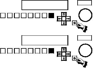
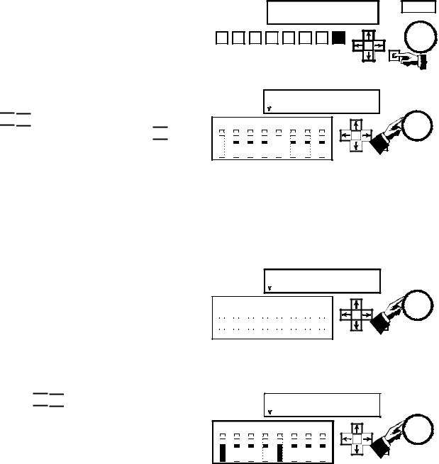
1.Select any Preset by pressing its PRESET button twice. The display should appear as illustrated.
2.Press the  button.
3.The NR2 TRIM value will now be flashing. Press the


 button so that the MENU option is flashing.
4.With the MENU option flashing, press the SELECT button.
SDDS
NR2
1 |
2 |
3 |
4 |
5 |
6 |
7 |
8 |
SELECT |
|
|
|
|
|
NR2 |
|
|
|
|
|
|
|
|
|
|
|
|
|
|
TRIM: 0 dB |
|
|
MENU |
|
|
|||||
|
|
|
|
|
|
|
|
|
|
|
|
|
|
|
|
|
|
|
|
|
|
|
|
|
|
|
|
|
|
|
|
|
|
|
|
|
|
|
|
|
|
|
|
|
1 |
2 |
3 |
4 |
5 |
6 |
7 |
8 |
|
|
|
|
|
|
|
|
|
|
|
|
|
|||||||||
|
|
|
|
|
|
|
|
|
|
|
|
|
|
|
|
|
|
|
|
|
|
|
|
|
|
|
|
|
|
|
|
|
|
|
NR2 |
|
|
|
|
|
|
|
|
|
|
|
|
|
|
TRIM: 0 dB |
|
|
|
MENU |
|
|
|||
|
|
|
|
|
|
|
|
|
|
|
|
|
|
|
|
|
|
|
|
|
|
|
|
|
|
|
|
|
|
|
|
|
|
|
|
|
|
|
|
|
|
|
|
|
1 |
2 |
3 |
4 |
5 |
6 |
7 |
8 |
SELECT |
|
DFP-3000 |
3-1 |
5.The STATUS option will now be flashing. Press the SELECT button again.
6.The firmware version will now be indicated in the upper right corner of the LCD display.
7.Press the SELECT button while the EXIT option is flashing to leave this area of the menu system.
STATUS CONFIG TEST
1 |
2 |
3 |
4 |
5 |
6 |
7 |
8 |
SELECT |
|
||||||||
|
|
|
PWR ON: 0 0 0 0 0 |
v2.74 |
||||
|
|
|
FILMRUN: 0 0 0 0 0 |
EXIT |
||||
1 |
2 |
3 |
4 |
5 |
6 |
7 |
8 |
SELECT |
|
||||||||
3.4 Check the version of the Setup Software on your computer.
The Setup Software is updated frequently. Be sure you are using the latest version, which will be v2.00, build 2.055 or higher. You can check the SDDS web site or contact Sony Cinema Products to determine the latest version and to request a free copy. You can check the version of Setup Software you are using by launching the program and selecting Help>About. . . from the pull down menu at the top of the main screen.
3.5 Confirm a proper chassis earth ground.
Most audio grounding schemes require that the chassis of the DFP-D3000 have a solid electrical connection to the rack in which it is mounted. The finish on the rack mounting rails may be very durable. Make sure that the mounting screws cut through the finish of the DFP-D3000 and that the mounting ears make electrical connection through the rack rails’ finish to the rack itself. Test this with an ohm meter. Additionally, a screw terminal Technical Ground is available on the back panel of the Decoder, to help make a solid ground connection. Do not remove the line cord safety ground pin in an attempt to avoid ground loops. This precaution is already taken care of in the design of the DFP-D3000 and removing the pin will have no benefit, but doing so will compromise electrical safety and may violate electrical codes.
3.6 Check the optical input connector wiring.
Make sure that the optical input connector is wired according to the pinout diagram in the Appendix. Use individually shielded twisted pair cable. See Chapter 5, A-Chain Alignment, for information regarding the optical pre-amp test points. Note that the wiring of this connector may not correspond to that of other cinema processors.
3.7 Confirm proper audio interface wiring.
The Sony DFP-D3000 Decoder unit uses professionally balanced audio interface connectors, pinned according to the THX convention, for interconnections to amplifiers, crossovers, limiters, booth monitors, and other cinema processors. Unfortunately, many such devices do not employ balanced inputs or outputs. It is essential that proper balanced to unbalanced interface wiring techniques are used when connecting to these devices so as to ensure optimum operating conditions for the DFP-D3000 and connected equipment. Failure to use proper techniques in your sound rack wiring may result in reduced system headroom, improper theatre calibration, and compromised sound performance. For a guide to properly interconnecting balanced and unbalanced audio signals, refer to Tech Note TN99060401.
3-2 |
DFP-3000 |
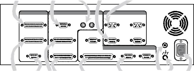
Wiring of other equipment.
This following is an illustration of the DFP-D3000 rear panel.
To balanced inputs |
From Mic 1 |
From Non-sync |
From Projector 1 |
From Projector 1 |
of booth monitor |
and Mic 2 |
player |
optical reader |
R3000 Reader |
OUTPUT |
INPUT |
|
|
|
PROJECTOR I/0 |
|
MONITOR OUTPUT |
MIC INPUT |
NON-SYNC |
1 |
READER |
2 |
|
|
|
R |
L |
|
|
|
SYSTEM OUTPUT |
AUX INPUT 1 |
|
REMOTE |
1 |
OPTICAL |
2 |
|
LEVEL |
|||||
|
|
|
CONTROL |
|
|
|
|
|
|
|
|
|
15V |
PHONES |
AUX INPUT 2 |
AUTOMATION |
|
CONTROL I/0 |
||
|
RS-232C |
RS-422 |
||||
|
|
|
|
|
||
To power amps |
To phones |
From other |
Automation logic |
To laptop PC via |
Backup |
Chassis |
120 / 230 |
and loudspeakers |
and HI |
cinema processors |
inputs and outputs |
null modem cable |
supply |
ground |
VAC |
Note that these D-Sub connectors have metric (M2.5 x.45) jack screw receptacles and require mating connectors with metric jack screws. A kit of such connectors is provided with each DFP D3000. Do not use standard D-Sub connectors with 4-40 jack screws.
Cinema processors.
Refer to the list of available Tech Notes in the Appendix of this Guide for instructions on correct audio and logic interconnections to other cinema processors. Note that Sony connectors use the THX® pinout convention, but other equipment may not. Therefore, pre-fabricated cables or cables made with flat ribbon computer-type cable are generally not acceptable for use with the DFP-D3000. The DFP-3000 cinema processor is capable of exceptional performance; do not degrade this by using inferior cables. Sony strongly recommends that all audio interconnections in your cinema sound rack be made using high quality audio-grade twisted pair shielded cables or individually shielded multipair cable. Contact your dealer for information regarding pre-wired audio cables for the DFP-D3000, available from several cinema accessory distributors.
Non-sync inputs.
The non-sync inputs of the DFP-D3000 are on consumer standard RCA-type connectors. One dedicated non-sync input is available. If additional non-sync inputs are required, the MIC1 input can easily be configured for line level operation, and the two eight-channel AUX inputs can serve as additional line level inputs for electronic projectors, DVD, magnetic film dubbers, and other external analog sound sources.
Microphone inputs.
The MIC1 and MIC2 inputs have built in microphone preamplifiers, so that external mixers or linematching devices are not required to directly connect a microphone level input. Input connections are balanced on a single D-Sub 9-pin female connector. 48-volt phantom power for condenser microphones is available, and can be switched on using the setup software or the front panel. See the instructions for MIC configuration later in this Guide for more detailed information.
DFP-3000 |
3-3 |
AUX inputs.
If either of the two 8-wide balanced AUX inputs are used for sources other than cinema processors, take note that the sophisticated automatic fallback system of the DFP-3000 requires these inputs to be enabled by a logic command to make them active. To use AUX1 or AUX2 for external sound sources other than digital film sound decoders, short Pin 34 (AUX1 DATA OK) or Pin 35 (AUX2 DATA OK) to GROUND on the Automation connector to enable the AUX1 or AUX2 inputs. See Tech Note TN99042801. Another approach is to chose No Fallback (*) as the fallback option for an AUX Preset, which prevents fallback and so forces the AUX input to play whenever it is selected.
Headphones and HI output.
A single D-Sub 9 pin connector provides a L/R stereo headphone output from the back panel. This is a parallel of the front panel headphone jack and is affected by the MONITOR SELECT switch and HEADPHONES level control. This connector also has two pins providing MONO outputs, which can be used to feed most Hearing Impaired transmission systems. Signal level for the HI outputs can be calibrated by an adjustment control located inside the Decoder. Detailed instructions for Hearing Impaired output level adjustment is discussed in Section 6.15 of this Guide.
Automation inputs and outputs.
All automation logic inputs and outputs are brought to a single 37-pin D-Sub connector on the DFPD3000. For a complete description of the connections available, see Tech Note TN99042801. Other Tech Notes describe specific means of connecting to other types of cinema equipment; see Tech Note TN99070701.
RS-232C connector.
This 9-pin female D-Sub connector is used to connect an external PC-compatible computer using a nullmodem cable.
RS-422 connector.
Contact your Sony service or sales representative for details on the use of this connector.
Remote level control.
Remote control of the Master Volume is possible by connecting a 100k-ohm linear taper potentiometer. The wiring convention of this potentiometer is unique to Sony, so follow the documentation in the Appendix carefully.
Bypass (backup) power supply.
The DFP-D3000 is provided with an external DC power supply which provides emergency power to bypass components within the Decoder. This power supply allows the Decoder to continue playing optical tracks in the event its main power has been turned off. Check that this power supply has the correct AC mains voltage rating for your country and is connected to the AC mains and to the back of the Decoder. A small red LED in the SELECT switch on the front panel of the Decoder indicates when the unit is being powered only by the backup power supply.
3-4 |
DFP-3000 |
4.Checks of correct DFP-R3000 Reader mounting.
Do not “hot plug” the Reader!
The Reader gets its power through the cable that connects it to the Decoder. Do not remove or install this cable while the Decoder power is on. Doing so may cause damage to the Reader and void the warranty.
4.1 Confirm the minimum frame offset.
Specific installation instructions for mounting the Reader to each type of projector are available in the DFP-R3000 Installation Guide provided with the Reader. Following these instructions will ensure at least the minimum frame offset between the Reader’s LEDs and the picture gate. The Reader LED offset must be at least 32 frames ahead of the projector gate. Since the loop ahead of the intermittent affects this offset, use a nominal loop when making this determination. The maximum total frame offset possible with the DFP-3000 is 115 frames.
4.2 Check the film path alignment.
Proper alignment of the film path entering and exiting the Reader, as well as adequate tension on the incoming film, is essential to correct operation of the DFP-R3000 Reader. Carefully check that the all rollers on the in-feed mechanism, the Reader, the Adapter plate, and the projector are aligned and that no twisting of the film path occurs. Adjust the positioning of the Reader if necessary.
DFP-3000 |
4-1 |
5.A-Chain alignment using DFP-D3000 front panel controls
The most direct means of A-Chain alignment is to use with external test equipment and the controls available through the Decoder front panel. There are two approaches. The first, recommended for experienced cinema engineers, is to align the projector’s optical playback system so as to produce nominal settings (preset gain = 0.0 dB) in the DFP-D3000. This has the potential benefit of best sound quality as preamplifiers, noise reduction, and matrix decoding circuits will be operating at optimal levels. The second approach is to set the DFP-D3000 to match the existing alignments in the projector’s optical playback system. This approach has the benefit of ease of setup, but requires that the optical system is already correctly aligned. Gain trims should end up near 0.0 dB with a properly aligned projector. With either approach, it is important to first ensure a high quality optical system alignment. For detailed instructions on aligning a forward scan optical reader system, see Tech Note TN99111901; to align a specific brand of reverse scan reader, follow its manufacturer’s documentation.
5.1 The following instructions require that the projector’s optical reader has been properly aligned, the projector is mechanically sound, and its optical playback system is clean. See TN99111901 for instructions on aligning a forward scan optical reader.
The initial steps for A-Chain alignment are common to both alignment approaches.
5.2.1Prepare a test cable.
This cable connects from a standard 1/4-inch stereo phone plug to the input connectors of your multichannel Real Time Analyzer (RTA) and simultaneously to the inputs of your dual-channel X-Y oscilloscope. The front panel phone jack on the Decoder has line-level output signals wired with Tip = Lt, Ring = Rt, and Sleeve = audio common (ground). The Lt and Rt signals connect to each input of your RTA and to the horizontal and vertical inputs of your oscilloscope. See available Tech Note TN99101201 for details on making up this test cable.
5.2.2Connect the test cable.
Set up your oscilloscope for X-Y display, i.e., to display phase relationships between two equal signals. Connect the test cable to the X and Y oscilloscope inputs. Connect Lt or Rt to your RTA input. Insert the phone plug end of the test cable into the headphones jack on the front panel of the DFP-D3000.
5.2.3 Set the MONITOR SELECT switch of the Decoder to position 1 (the LCD screen will briefly display L+LC+C+SL/R+RC+SR). Set the adjacent HEADPHONES volume control to the 12:00 (straight up) position.
5.3 Enter the A-Chain access password in order to adjust preamplifier gains and set the slit loss equalization frequency. You will need to play customary alignment films at times during this process. The default A-Chain password is “SONY”.
DFP-3000 |
5-1 |
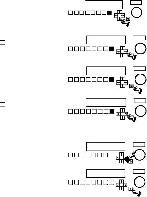
5.3.1Select any Preset other than non-sync by pressing its PRESET button twice. If you have selected Preset 8 for SDDS the LCD display will appear as illustrated.
5.3.2Press the  button.
5.3.3The NR2 TRIM value will now be flashing. Press
the 

 button so that the MENU option is flashing.
5.3.4With the MENU option flashing, press the SELECT button.
SDDS
NR2
1 |
2 |
3 |
4 |
5 |
6 |
7 |
8 |
SELECT |
|
NR2 |
|
TRIM: 0 dB |
MENU |
1 |
2 |
3 |
4 |
5 |
6 |
7 |
8 |
SELECT |
|
NR2 |
|
TRIM: 0 dB |
MENU |
1 |
2 |
3 |
4 |
5 |
6 |
7 |
8 |
SELECT |
|
5.3.5The STATUS option will now be flashing. Press
the 

 button again. This will cause the CONFIG option to flash.
5.3.6With the CONFIG option flashing, press the SELECT button.
STATUS CONFIG TEST
1 |
2 |
3 |
4 |
5 |
6 |
7 |
8 |
SELECT |
|
5.3.7Turn the MASTER VOLUME control clockwise until the first character in the password field is changed to “S”. The default A-Chain password is “SONY”.
5.3.8When the first character becomes “S”, press the SELECT button to enter it and move to the next character. Continue using the MASTER VOLUME control and SELECT button to enter all characters of SONY.
5-2
PASSWORD: * * * *
|
|
|
|
|
|
|
|
|
|
|
|
|
|
|
|
|
|
|
|
1 |
2 |
3 |
4 |
5 |
6 |
7 |
|
8 |
|
|
|
|
|
||||||
|
|
|
|
|
|
|
|
|
|
|
|
|
|
|
|
|
|
|
|
PASSWORD: S * * *
|
|
|
|
|
|
|
|
|
|
|
|
|
|
|
|
|
|
|
|
1 |
2 |
3 |
4 |
5 |
6 |
7 |
|
8 |
|
|
|
|
|
||||||
|
|
|
|
|
|
|
|
|
|
|
|
|
|
|
|
|
|
|
|
MASTER VOLUME
SELECT
MASTER VOLUME
SELECT
DFP-3000
5.3.9When you enter the last correct character you will see the ADMIT option flashing. Press the SELECT button to proceed to the A-Chain functions menus.
5.3.10This is the A-Chain Calibration menu for OPT1L
(the left optical input from projector 1). Use the


 buttons to select among left and right inputs from two projectors and the


 buttons to select between Slit Loss and Gain
adjustments. The MASTER VOLUME control adjusts the values of GAIN or S_LOSS.
|
|
|
PASSWORD |
|
|
|||
|
|
|
ADMIT |
|
CHANGE: SONY |
MASTER VOLUME |
||
1 |
2 |
3 |
4 |
5 |
6 |
7 |
8 |
SELECT |
|
||||||||
OPT1L GAIN: 0.0 dB |
EXIT |
|
I S_LOSS 20kHz |
MASTER VOLUME |
|
|
|
|
L LC C RC R SW LS RS |
|
|
You must now decide whether to align the optical reader to the DFP-D3000 or the DFP-D3000 to the reader. If you decide to adjust the reader to achieve gain settings of 0.0 dB (or as close as possible) you must make adjustments to the exciter lamp voltage or reverse scan preamplifier gain, and possibly other adjustments, according to your experience. Otherwise, use the following steps to adjust the DFP-D3000 to accommodate the correctly aligned reader’s output.
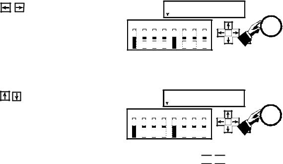
5.4a Play a Calibration Tone loop. The signal amplitude will be indicated on the L and R meters, while the single LED on the remaining meters serves as a reference. Use the Master Volume control to set the gain for the Left optical input from projector 1 (OPT1L) to match the single LED’s as shown. Note that the meter sensitivity in this calibration mode is much higher than in normal film playback operation.
5.4b Use the 


 buttons to select the Right optical input (OPT1R) and use the Master Volume control to set the gain so that the signal level is correct. If you chose to align the reader to the DFP-D3000, you would have the L and R bars aligned to match the single LED’s and all gain settings would be at 0.0 dB.
OPT1L GAIN: 1.6 dB |
|
I S_LOSS 20kHz |
EXIT |
L LC C RC R SW LS RS
|
|
|
|
|
|
|
|
|
|
|
|
|
|
|
|
|
|
|
|
|
|
|
|
|
|
|
|
|
|
|
|
|
|
|
|
|
|
|
|
|
|
|
|
|
|
|
|
|
|
|
|
|
|
|
|
|
|
|
|
|
|
|
|
|
|
|
|
|
|
|
|
|
|
|
|
|
|
|
|
|
|
|
|
|
|
|
|
|
|
|
|
|
|
|
|
|
|
|
|
|
|
|
|
|
|
|
|
|
|
|
|
|
|
|
|
|
|
|
|
|
|
|
|
|
|
|
|
|
|
|
|
|
OPT1R |
GAIN: 2.4 dB |
|
|
|
|||||||||
|
|
|
|
|
|
|
I S_LOSS |
|
|
20kHz |
EXIT |
|||||||||
|
|
|
|
|
|
|
|
|
|
|
|
|
|
|
|
|
|
|
|
|
L LC C RC R SW LS RS
MASTER VOLUME
MASTER VOLUME
DFP-3000 |
5-3 |
5.5a |
Use the |
buttons to change the selected |
|
|
OPT1R |
|
GAIN: 2.4 dB |
EXIT |
|
|
parameter to slit loss (S_LOSS). Play a B&W Pink |
|
|
I S_LOSS |
16.4kHz |
MASTER VOLUME |
|||
|
|
|
|
|
|
|
|
||
|
Noise test film and use the Master Volume control |
L |
LC |
C RC R SW LS RS |
|
|
|||
|
to adjust the slit loss frequency to achieve the |
|
|
|
|
|
SELECT |
|
|
|
flattest response, as indicated by your RTA. The |
|
|
|
|
|
|
|
|
|
result that is achievable depends on the slit height |
|
|
|
|
|
|
|
|
|
and other properties of the reader and the actual |
|
|
|
|
|
|
|
|
|
high frequency flatness of your pink noise test |
|
|
|
|
|
|
|
|
|
film. |
|
|
|
|
|
|
|
|
5.5b |
Use the |
buttons to return to the Left |
|
|
OPT1L |
GAIN: 2.4 dB |
EXIT |
|
|
|
optical input and use the Master Volume control to |
|
|
I S_LOSS |
16.4kHz |
MASTER VOLUME |
|||
|
|
|
|
|
|
|
|
||
|
adjust the slit loss compensation frequency to |
L |
LC |
C RC R SW LS RS |
|
|
|||
|
achieve the flattest response. |
|
|
|
|
|
SELECT |
|
|
|
|
|
|
|
|
|
|
|
|
This completes the A-Chain alignment procedure. To return to the main LCD menu, use the 


 buttons to select the EXIT option and press the SELECT button. You may also press any PRESET button twice to exit all menus and return the Decoder to normal operation with that Preset selected and its parameters loaded.
5-4 |
DFP-3000 |
6.B-Chain Alignment
B-Chain alignment is performed using the DFP-D3000, Setup Software, and your own test equipment. To begin, connect your computer to the Decoder using a null modem cable, launch the Setup Software, and “connect” the Setup Software to the DFP-D3000 using the Config>Connect to DFP… menus. Set up your microphones and analyzer (THX R2 or other multichannel real time analyzer) in the theatre. Refer to SMPTE Standard 202M, B-Chain Electroacoustic Response, for more detailed information on microphone placement, theatre acoustics, and the “X” curve. Note that the DFP-D3000 must be set up with the Master Fader nominally set to 0.0 (not 7) and that from this position 10 dB of boost and full cut is available, with an audio/dB fader taper.
6.1Open the Master DFP-3K Settings screen by selecting Master DFP-D3000 under the Master option in the main screen menu bar.
6.2Ensure that the Master Volume is set to 0.0 dB. Select
the appropriate output level for the DFP-D3000; this is the absolute signal level that corresponds to the _20
dBFS reference point. In most cases you should chose _10 dBu (145 mV).
Use your real time analyzer (RTA) to check the SPL in the theatre and ensure that it is in the right range when the Master Volume is 0.0 dB.
6.3a Move all Channel Level Trims to the center setting (0.0 dB). Center all equalizer sliders at 0.0 dB. To quickly set all EQ levels to 0.0 dB, access the Reset Channel function in the Tools pull-down menu located in the main screen menu bar. The illustration shows the main screen of the Setup Software in this condition, for the Left output channel.
DFP-3000 |
6-1 |

6.3b Link the channel mutes to the channel selects using the Tools selection of the main screen and selecting Link Mute Channels to Channel Select.
6.3c To bring up the DFP Test Signal Generator screen, select the Signal Generation option under the Test item on the main screen menu bar.
6.4a Select Pink Noise in the Signals area. Pink noise can be sent to the outputs only at _20 dBFS. This is handled automatically by the software.
6.4b Enable all outputs by selecting All On in the Output Channel area. The software automatically mutes all channels to prevent accidentally sending loud sounds into the theatre.
When All On is selected, a warning will appear. Read it carefully and select Yes if you wish to continue.
When you finish the setup, return to the main screen by pressing Exit.
Note that the bottom of the main screen now shows PINK to indicate that pink noise is being generated and Linked to show that channel mutes are linked to channel selects.
6-2 |
DFP-3000 |

6.4c B-Chain alignment is performed on output channels individually. You can use the function keys as an aid in channel selection or use the MUTE/ON buttons illustrated in 6.3a. Because the channels are linked, pressing a function key or button selects and un-mutes (turns on) that channel while muting (turns off) all other output channels.
Function Key |
Channel |
F1 |
Left |
|
|
F2 |
Left Center |
|
|
F3 |
Center |
|
|
F4 |
Right Center |
|
|
F5 |
Right |
|
|
F6 |
Subwoofer, (LFE) |
|
|
F7 |
Left Surround |
|
|
F8 |
Right Surround |
|
|
6.5Now select each output channel in succession, confirm that the noise sound is coming from the correct loudspeaker, and adjust the channel’s equalization and level. Start by adjusting the equipment between the System Outputs of the DFP-D3000 and the loudspeakers to achieve about 85 dBC SPL in each screen loudspeaker, measured individually (82 dBC for each of the two surround channels). This equipment may include crossovers and power amplifiers from a number of manufacturers so specific instructions cannot be given here. Sony recommends using several measurement microphones and a microphone multiplexer to drive your RTA, but each engineer will have their own preferred measurement techniques.
6.6Adjust the graphic equalizer to achieve the “X” curve of SMPTE 202M, or other frequency response that has been established for your theatre. Do this for each loudspeaker attached to an output channel, except the subwoofer. Setting the graphic equalizer for best results requires skill and experience, but a few general points can be made. Make small adjustments and let the RTA display settle down after each adjustment. Cutting EQ is always better than boosting EQ. Adjacent bands with boost and cut differences of more than 3dB indicates problems that aren’t appropriate for EQ to correct; try to end up with a smooth equalizer setting using as little EQ as possible and no more than a few dB difference between adjacent bands. Use even less EQ on the surround loudspeakers. The screen speakers should all have the same EQ settings (if they are the same cabinet type); if they aren’t very close, there may be problems that EQ should not be used to address. Don’t boost low bands in an attempt to extend the low frequency response; that is mainly determined by the cabinet design. Remember that you can only adjust for the sound that comes directly from the loudspeakers to the measurement microphone; you cannot do much about the sound that is influenced by the auditorium acoustics or resonances and you should avoid the temptation to try to do so. If you see wide variations when you move your microphones around in the auditorium, position them closer to the front so as to measure more sound direct from the loudspeakers and have less influence from the sound that has bounced around the auditorium (which you can’t affect with EQ).
6.7When all loudspeakers except the subwoofer have been EQ’d, make a wideband adjustment in the equipment between the DFP-D3000 and each of the loudspeakers (such as with a power amplifier gain control) to achieve 85 dBC SPL from each screen loudspeaker. This is a wideband sound pressure measurement; at this point, the individual bands of your RTA will each be at about 70 dB SPL. The left and right surround cabinet groups should each be set for 82 dBC wideband. It is better to achieve this result with an adjustment of amplifier gain than by using a Channel Level Trim, and
when using a Channel Level Trim, it is better to preserve full headroom by using attenuation (cut, or _dB) instead of gain (boost, or +dB).
DFP-3000 |
6-3 |
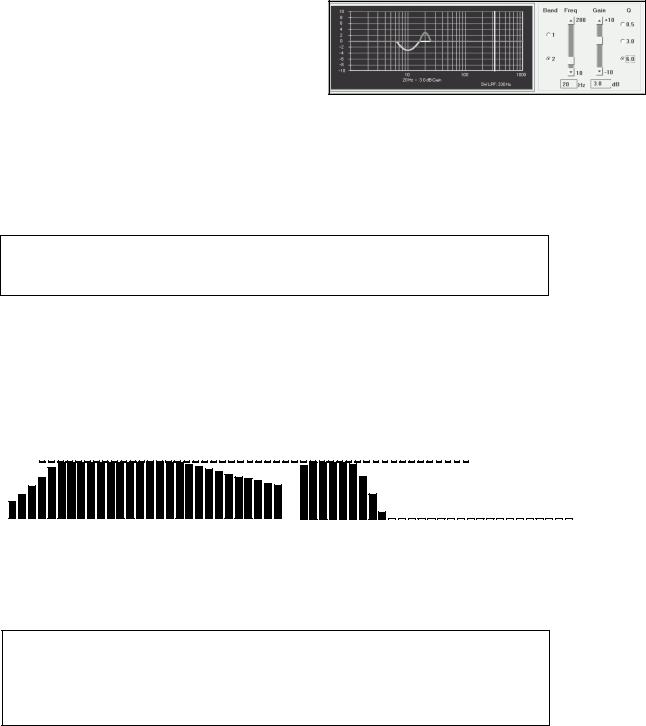
6.8To set the equalization for the subwoofer loudspeaker, press F6 to select the Subwoofer output channel and bring up the 2-band parametric equalizer. Verify that sound is coming from the subwoofer loudspeaker cabinet.
Adjusting the subwoofer equalizer is especially difficult and benefits from experience with the particular cabinet model used. Use as little EQ as possible and allow your RTA display extra time to settle between adjustments. Aim for a smooth, rather than extended, response. Note that the higher frequencies are rolled off by the subwoofer low pass filter, whose frequency is shown below the graphic display and is indicated by the vertical yellow line. Use 330 Hz for this step and reduce the setting later, using separate settings for optical, digital, and other presets.
The analog subwoofer channel level trim affects the subwoofer output level of all eight presets. The SDDS subwoofer level is an offset trim from this value. The AUX subwoofer offset settings are also offset from the analog subwoofer channel level trim.
6.9The recommended method of setting the analog subwoofer level is to use the internal pink noise generator as you have previously done for the screen speakers and adjust the subwoofer power amplifier input gain control and the subwoofer level trim (which is essentially in series with the subwoofer power amplifier’s input gain control) to make the subwoofer’s RTA bands match the level of the Center channel’s RTA bands where they are flat. Use attenuation in preference to gain at the subwoofer level trim and achieve gain with the subwoofer power amplifier’s input control. When you make a change to the Analog Channel Level Trim slider while the Subwoofer output channel is
selected, the software will automatically select a non-SDDS Preset.
|
|
|
|
|
|
|
|
|
|
|
|
|
|
|
|
|
|
|
|
|
|
Same SPL |
|
|
|||
40 |
63 |
100 |
160 |
250 |
400 |
630 |
1K |
1.6K |
2.5K |
4K |
6.3K |
10K |
16K |
40 |
63 |
100 |
160 |
250 |
400 |
630 |
1K |
1.6K |
2.5K |
4K |
6.3K |
10K |
16K |
Center channel loudspeaker response |
Analog subwoofer channel response |
Purists may want to set the optical subwoofer level by playing a pink noise loop and adjusting to make the overall response of the screen speakers as flat and extended as possible as a result of the subwoofer’s supplementation. This technique is beyond the scope of this Guide.
Recognize that the SDDS (and other digital formats’) subwoofer is an effects channel that delivers low frequency sounds that are designed to enhance certain elements of a particular film. The analog subwoofer is derived from the optical L,C,R channels and is intended to compensate for limitations of the screen speakers being used; modern, full-range screen loudspeakers may need little or no analog subwoofer supplementation. For a longer discussion, see Tech Note TN99051701.
The low pass filter frequency for the optical preset must first be set to match the response of the subwoofer to the response of the screen speakers. Wide range screen speakers can have the optical subwoofer low pass filter set to the lowest value of 80 Hz; 100 Hz is a good starting point for most modern screen loudspeakers.
What ever method is used, a final listening test, using film having a high quality optical track with familiar, wide range content should be auditioned to ensure that the subwoofer level is set for best sound and optimal low frequency balance. If you use a non-sync audio source, such as a music CD, for this test, be sure to select Mode 6, 7, 8, or 9 for your non-sync Preset in the Preset Configuration
6-4 screen (see Step 6.11), so that the analog subwoofer output is active.
DFP-3000
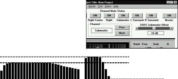
6.10When adjusting the SDDS subwoofer (LFE) level offset, the SDDS Preset must be made the active Preset. Select the preset manually with the Active Preset option under the Presets item in the main screen menu bar and then selecting the SDDS Preset, or by clicking the appropriate radio button at the lower left of the main screen.
8 is the default preset for SDDS. Press F6 to manually the subwoofer output channel. Alternatively, the software will automatically select the SDDS Preset when you have selected the Subwoofer output channel and click the SDDS Subwoofer Offset slider.
Use the SDDS Subwoofer Offset slider control and your real time analyzer (RTA) to set 10 dB of inband gain of the subwoofer’s bands as compared to the previously calibrated Center speaker’s bands in the region of its flat frequency response. Be sure to allow extra time for the low frequency bands to settle to their final values.
40 |
63 |
100 |
160 |
250 |
400 |
630 |
1K |
1.6K |
2.5K |
4K |
6.3K |
10K |
16K |
40 |
63 |
100 |
160 |
250 |
400 |
630 |
1K |
10dB higher SPL
1.6K 2.5K 4K 6.3K 10K 16K
Center channel loudspeaker response |
Digital subwoofer (LFE) channel response |
This procedure, which requires an RTA, matches the playback gain of the SDDS Preset’s subwoofer loudspeaker in the cinema to the playback response of the digital subwoofer (LFE loudspeaker) on the stage where the film’s sound track was mixed.
When evaluating the SDDS digital subwoofer (LFE) level, no listening test is entirely definitive, because the amount of energy in the LFE channel is a creative decision made when the soundtrack of each film was mixed. For the same reason, the digital subwoofer (LFE) low pass filter setting has no relationship to the screen loudspeakers’ performance. It merely serves to exclude undesirable sound from the subwoofer (LFE) cabinet. The actual sounds reproduced on the digital subwoofer (LFE) channel are determined by what was put there by the film’s sound mixer, as long as the filter frequency is not set so low as to remove sounds the mixer intended to be included. Setting the digital subwoofer low pass filter frequency to 100 to 200 Hz should be acceptable and either setting should sound the same when actual film is exhibited; start with 160 Hz. Subwoofer manufacturers may have specific recommendations for their cabinets.
Note that the result of a wideband SPL measurement of pink noise from the SDDS subwoofer (LFE) will depend on both the level Trim setting and the low pass filter Frequency setting. For a LPF frequency setting of 100 Hz, a wideband measurement made with an SPL meter will show approximately 91 dB. Such a measurement should only be made to confirm that a correctly calibrated theatre has not drifted, and cannot be used as a primary calibration measurement in place of an RTA. Also remember that the analog subwoofer channel trim is effectively in series with the subwoofer amplifier’s input gain control. This means that an adjustment to the analog subwoofer channel trim also affects the playback level of all digital subwoofer signals.
DFP-3000 |
6-5 |
Note that the graphic and parametric equalizer settings adjust for the frequency response of each of the loudspeaker cabinets in the theatre. This means they affect the output from all Preset inputs. The output channel level trims, including the analog subwoofer channel level trim, also affect all Presets. These settings are retained in the DFP-D3000’s non-volatile memory as a single set of overall adjustments to the playback system. Other settings, such as subwoofer low pass filter frequency and surround speaker delay, may be unique to each format or signal source. These values are stored as individual settings for and within each of the eight Presets.
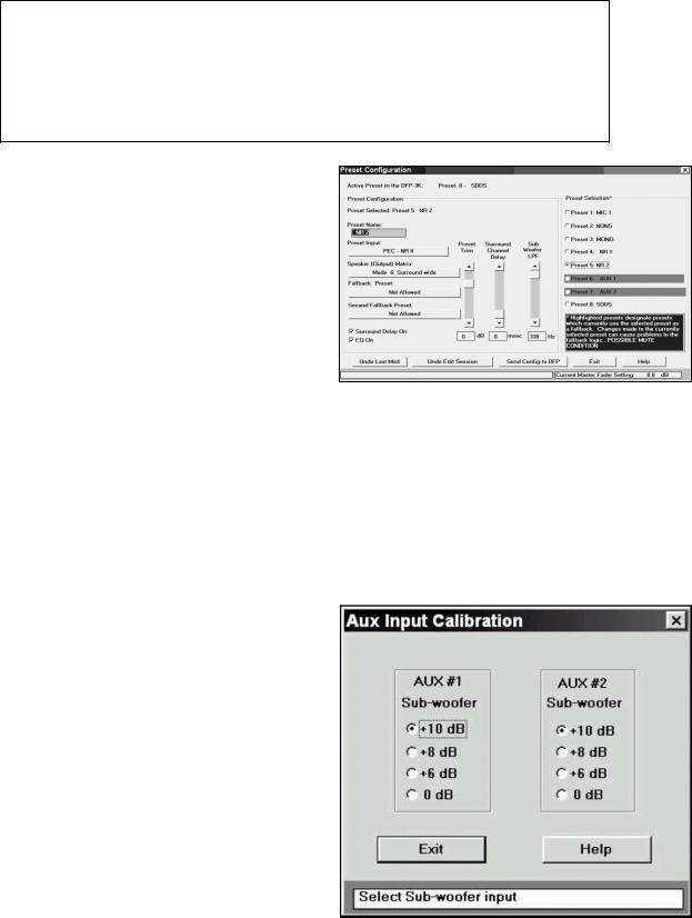
6.11To set the surround channel delay and enable it for each Preset, bring up the Preset Configuration screen by selecting the Preset Configuration option under the Presets item in the main screen menu bar. This screen allows you to select each Preset, make a level trim (to balance the relative level of each Preset), set a surround delay, and set the subwoofer low pass filter (LPF) frequency for that Preset.
In the latest versions of software you can also set surround delay and subwoofer LPF frequency at the main screen, according to the output channel selected.
The surround channel delay can be set with elaborate science based on SMPTE 202M. However, an easy rule-of-thumb approach is to set the
milliseconds of delay for optical sources (NR2) to equal the length of the theatre (in feet) +10. For
digital sources (SDDS) it should be set to 60 % of the optical surround delay.
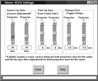
6.12If a cinema digital audio system is connected to one of the AUX inputs, you must set its corresponding subwoofer input level offset. The playback level of the subwoofer in today’s cinema digital audio systems is offset by 10 dB. To access the AUX Input Calibration screen, select the AUX Inputs option from the A-chain item in the main screen menu bar. Click to select the correct offset.
6-6 |
DFP-3000 |
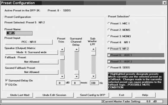
6.13 To adjust the synchronization between optical and SDDS playback, access the Master SDDS Settings screen by selecting Master SDDS from the Master item on the main screen menu bar.
First set the coarse adjustment of frame offset by counting the actual frames of film between the projector’s film gate and the LEDs of the DFPR3000 Reader. You must have at least 32 frames. This adjustment cannot be changed while film is running.
Now adjust the Fine Lip Sync by playing the SDDS Installation reel or a quality, dialog-heavy feature print (not a trailer, which may have loose sync) and comparing optical and digital dialog. Set the fine lip sync to make the two coincident. Do this by plugging headphones into the front panel of the DFP-D3000 and turning the Monitor switch to position 5 (the LCD display will briefly indicate “Lt+Rt/SOURCE_Cch”). The left output will contain the optical center channel and the right output will contain the digital center channel audio. Verify your setting by watching the film from a mid-audience position and check that the dialog synchronization appears to be correct; don’t use the projection booth monitor while looking through the booth’s port hole or you will retard the sound by about two frames.
The DFP-D3000 allows you to use this same feature to check synchronization of the AUX input signals. This means that if you also have DTS or SRD sources you can check their synchronization against the optical tracks, even though their manufacturers do not offer this capability.
6.14 |
Setting up Preset configurations. A Preset is a set of retained DFP-D3000 Decoder settings that apply |
||
|
to a particular input signal. These settings are associated with eight numbered switch buttons on the |
||
|
front panel of the Decoder which are used to select inputs. Pressing any of these buttons once will |
||
|
cause the LCD screen to display its current assignments; this is only a display function. Pressing a |
||
|
button twice will select its associated input as the signal source for the Decoder and will also load the |
||
|
corresponding Preset’s retained parameters. |
|
|
|
Sony recommends that these default Preset assign- |
|
|
|
Button |
Input Signal Type |
|
|
ments be Maintained, but the signal type can be |
||
|
|
|
|
|
1 |
Microphone |
|
|
renamed for convenience. For Example, AUX1 |
||
|
|
|
|
|
2 |
Non-sync |
|
|
could be renamed to DTS, but keep it as Preset 6 |
||
|
|
|
|
|
3 |
PEC - Academy mono |
|
|
unless you have good reason to do otherwise. |
||
|
|
4 |
PEC - NR1 |
|
|
|
|
|
|
5 |
PEC - NR2 |
|
|
|
|
|
|
6 |
AUX1 |
|
|
|
|
|
|
7 |
AUX2 |
|
|
|
|
|
|
8 |
SDDS |
|
|
|
|
DFP-3000 |
6-7 |
The following parameters are stored in the DFP-D3000 for each Preset: Preset name (up to 12 user-entered characters)
Input signal type (microphone, non-sync, PEC, AUX, or SDDS) Speaker output matrix (1 of 16 available matrix options) Fallback presets (for presets with AUX or SDDS input formats) Preset trim (fader offset for each Preset)
EQ On/Off switch
Surround delay On/Off switch Surround delay
Sub-woofer low pass filter frequency
Fade in time (same for all non-sync presets)
To change these parameters, access the Preset Configuration screen from the Preset Configuration option under the Presets item in the main screen menu bar.
To re-configure a Preset, select the candidate Preset from the list of preset configurations in the Preset Selection area of the screen. After selecting the Preset, the various fields in the Preset Configuration area will change to reflect its current configuration. If the selected Preset is a fallback assignment for other Presets (in the event their digital data becomes unavailable), such Presets will be highlighted in red in the Preset Selection area. If a change is made to the selected Preset which renders it invalid as a fallback for one of its highlighted Presets, the setup software will display a warning and attempt to select another valid Preset to replace the one you have modified. A list of changes will be displayed when the modified Preset’s new configuration is sent to the DFP-D3000 Decoder. If you are using firmware v3.0 or later, check with Sony to see if changes have been made to functions available from the Preset Configuration screen.
The Preset Name edit box is used to change the name of a preset configuration. Alternate Preset names are entirely up to the user, but cannot exceed 12 characters in length. The Setup Software automatically formats the name to center it in the DFP-D3000 front panel LCD display. To change the input signal type, click on the Preset Input edit box and select the signal type from a list that pops up. Sony suggests that you maintain the default selections.
6-8 |
DFP-3000 |

To change the output format for the selected Preset, click on the Speaker (Output) Matrix edit box and select from the list that pops up. This list automatically contains only those matrix formats that are allowed for the type of input signal that you have chosen. Here are all the matrix modes and their meanings:
Mode |
Name |
Meaning |
|
|
|
1 |
SDDS |
Eight inputs sent directly to eight outputs |
|
|
|
2 |
SDDS 7.1CH |
#1 except LC and RC mixed into L, C, R; SW to SW, LC, and RC outs |
|
|
|
3 |
SDDS 6CH |
#1 except LC and RC mixed into L, C, R; SL +SR to SL out; SW to LC and RC |
|
|
|
4 |
SDDS 5.1CH |
#1 except LC and RC mixed into L, C, R; SW in to SW out only |
|
|
|
5 |
SDDS 4CH |
#1 except LC and RC mixed into L, C, R; SL +SR to SL out; SW to SW only |
|
|
|
6 |
Surround wide |
L, R matrix decoded as Lt, Rt, bass extended; to L, C, R, SL = SR, SW |
|
|
|
7 |
Surround narrow |
L, R matrix decoded as Lt, Rt, bass extended; to LC, C, RC, SL = SR, SW |
|
|
|
8 |
Stereo wide |
L, R in to L, R out; bass extension synthesized and sent to SW |
|
|
|
9 |
Stereo narrow |
L, R in to LC, RC out; bass extension synthesized and sent to SW |
|
|
|
10 |
Mono |
C in to C out with Academy Filter; SW output off |
|
|
|
11 |
Normal |
L, R in to L, R out; SW output off |
|
|
|
12 |
Normal narrow |
L, R in to LC, RC out; SW output off |
|
|
|
13 |
Matrix decode W |
L, R matrix decoded as Lt, Rt and sent to L, C, R, SL = SR; SW off |
|
|
|
14 |
Matrix decode N |
L, R matrix decoded as Lt, Rt and sent to LC, C, RC, SL = SR; SW off |
|
|
|
15 |
Surround |
L, R in to SL, SR out; SW output off |
|
|
|
16 |
LRS |
L, R matrix decoded as Lt, Rt and sent to L, R with SL = SR; SW off |
|
|
|
For the AUX1, AUX2, and SDDS Presets, fallback Presets can be selected. To select a fallback Preset, use the edit button just below the Fallback Preset label. If no fallback is permitted for the type of input you have selected, this button will indicate Not Allowed. Otherwise, when you click on it, a selection list will pop up which shows all Presets including No Preset, with prohibited Presets grayed out to indicate they are unavailable. The SDDS Preset allows selection of a second fallback preset making it possible for all digital formats to be played automatically with optical as an overall fallback if no digital formats are available on a particular reel. For example, the fallback sequence SDDS → AUX1 → AUX2 → NR2 indicates that if SDDS data becomes unavailable, the DFP-3000 will fall back to its AUX1 input. If neither formats are available, the DFP-3000 will fall back to its AUX2 input. Finally, if no digital formats of any kind are available, the DFP3000 will fall back to its optical (NR2) input. All this assumes, of course, that the other digital systems are installed and that their logic interfaces are properly wired to the DFP-D3000.
For each Preset, graphic and parametric equalization can be switched on or off, surround delay processing can be switched on or off, the number of seconds of surround delay can be set if surround delay processing is switch on, a volume offset for the preset can be specified, and the sub-woofer low pass filter frequency can be set. To select and set these parameters, use the appropriate control in the Preset Configuration area of the screen. If the test signal generator is running, only the preset offset, surround channel delay and EQ on/off switch controls, surround delay setting, and the sub-woofer low pass filter frequency controls are active.
After making modifications to a Preset Configuration, use the Send Config to DFP button to send the changes to the DFP-3000 decoder from your connected laptop. Even if the Send Config to DFP button is not used, the Setup Software will automatically send the new parameters to the DFP-3000 decoder when the Exit button for the Preset Configuration screen is clicked. Save these settings as a theatre file when prompted in case they need to be restored to recover from unintended changes, transferred to another processor, or reloaded to the DSP-82 board if it is ever replaced.
DFP-3000 |
6-9 |

6.15At this point the DFP-3000 system needs only a few final adjustments. The Preset level trims can be set according to the preferred methods of each cinema engineer. To access the trim of a Preset from the front panel, select the Preset by pressing its button twice and then press the Down arrow. Adjust the Master Volume control to change the preset trim in order to match the Preset to the SDDS loudness level; when satisfied with the level, press the Up arrow to store the setting and return to normal operation. Some may chose to adjust external non-sync distribution amplifiers to achieve the desired level and leave the DFP-D3000 non-sync trim at 0.0 dB. If the screen has additional digital formats, play a quad format feature and block the LEDs of the various readers and use the DFP-D3000’s fallback system to automatically switch between formats, comparing loudness by listening to the booth monitor. This allows checking the fallback wiring as well as the preset level matching. Normally, it is best to use output trims on the other digital players to achieve 85 dB SPL at each speaker in the same manner as was done for the SDDS format with the DFP-D3000 (using pink noise and an SPL meter), but the Preset trims can also be used if convenient. When making this test, blocking the DFP-R3000 reader’s LEDs will allow you to confirm operation of the SDDS ACM (Analog Concealment Mode) fallback to optical or other preset.
The bypass level setting is made by adjusting two trimmer potentiometers (for Lt and Rt) located at the left of the lower circuit board inside the DFP-D3000. These are adjusted to produce the same output level to L and R when the unit is powered Off while playing a pink noise loop through the optical inputs. Remove two silver screws at the right of the front panel and swing it aside to reach these two trim controls.
|
Lt Rt |
HI |
APR-34 rev 11 circuit board (lowest of 3) |
|
|||||
|
|
|
|
|
|
|
|
|
|
|
|
|
|
|
|
|
|
|
|
|
|
|
|
|
|
|
|
|
|
APR-34 rev 12 circuit board (lowest of 3)
The single HI (hearing impaired) output level trim potentiometer is located to the right of the bypass level trim controls and is marked HI on the circuit board. It adjusts the HI output from .7 to 7 V at its rear panel PHONES connector.
6-10 |
DFP-3000 |
 Loading...