


TCL
WALL MOUNTED SPLIT-TYPE AIR CONDITIONERS
SERVICE MANUAL |
No.TE080528 |
Models
KFTHP-12
KFTHP-18
KFTHP-24
CONTENTS
1. |
IMPORTANT NOTICE |
···································2 |
2. |
TECHNICAL SPECIFICATION ·····················3 |
|
3. |
OPERATION DETAILS·······································4 |
|
4. |
ELECTRICAL SCHEMATIC DIAGRAM ·········· 13 |
|
5. |
EXPLOSION VIEW |
····························16 |
6. |
PARTS LIST |
·············22 |

TCL Air Conditioner Service Manual
IMPORTANT NOTICE
This service manual is intended for use by individuals possessing adequate backgrounds of electrical, electronic and mechanical experience. It is to be installed and service by a licensed HVAC technician. Any attempt to repair the appliance may result in personal injury and property damage. The manufacturer or seller cannot be responsible for the interpretation of this information, nor can it assume any liability in connection with its use.
The information, specifications and parameter are subject to change due to technical modification or improvement without any prior notice. The accurate specifications are presented on the nameplate label.
How to order spare parts
To have your order filled promptly and correctly, please furnish the following information:
1.Model No. with Indoor or Outdoor
2.No. in the Explosion View
3.Part Name
4.The quantity you ordered
2

TCL Air Conditioner Service Manual
Technical Specifications
Model No. |
|
|
|
|
|
KFTHP-12 |
|
KFTHP-18 |
KFTHP-24 |
|
|
Type |
|
|
|
|
|
|
Heating pump |
|
Heating pump |
Heating pump |
|
Control type |
|
|
|
|
|
Remote |
|
Remote |
Remote |
|
|
Rated cooling capacity |
|
|
Btu/h |
12500 |
|
18000 |
24000 |
|
|||
Rated heating capacity |
|
|
Btu /h |
12000 |
|
17300 |
23500 |
|
|||
SEER |
|
|
|
|
|
Btu/W.h |
13.1 |
|
13.3 |
13.0 |
|
HSPF |
|
|
|
|
|
Btu/W.h |
8.8 |
|
8.1 |
8.5 |
|
Moisture removal |
|
|
Liters/h |
1.2 |
|
1.5 |
2.0 |
|
|||
Indoor |
noise |
level at |
|
High |
|
dB(A) |
42 |
|
56 |
57 |
|
|
Med. |
|
dB(A) |
40 |
|
54 |
55 |
|
|||
cooling |
|
|
|
|
|
|
|||||
|
|
|
Low |
|
dB(A) |
38 |
|
50 |
52 |
|
|
|
|
|
|
|
|
|
|||||
Outdoor sound power level |
|
|
dB(A) |
52 |
|
54 |
59 |
|
|||
Electrical Data |
|
|
|
|
|
|
|
|
|
|
|
Power supply |
|
|
|
|
|
|
|
60Hz/1P |
|||
Voltage range |
|
|
|
|
V |
208-230V |
|
208-230V |
208-230V |
|
|
Rated current |
|
|
Cooling |
|
A |
4.6 |
|
6.7 |
9.7 |
|
|
|
|
Heating |
|
A |
4.6 |
|
6.4 |
9.7 |
|
||
|
|
|
|
|
|
|
|||||
Rated input |
|
|
Cooling |
|
W |
1000 |
|
1550 |
2050 |
|
|
|
|
Heating |
|
W |
1000 |
|
1500 |
2050 |
|
||
|
|
|
|
|
|
|
|||||
Refrigerating System |
|
|
|
|
|
|
|
|
|||
Refrigerant/Charge |
|
|
Gram |
R410A |
|
R410A |
R410A |
|
|||
|
|
|
|
Type |
|
Rotary |
|
Rotary |
Rotary |
|
|
Compressor |
|
|
Model |
|
------------------ |
|
----------------- |
-------------- |
|
||
|
|
LRA |
|
A |
------ |
|
------- |
--------------- |
|
||
|
|
|
|
|
|
|
|||||
|
|
|
|
MFG |
|
----------------- |
|
----------------- |
--------------- |
|
|
Expansion device |
|
|
|
|
|
Capillary tube |
|||||
Defrosting system |
|
|
|
|
Microcomputer controlled reverse system |
||||||
Fan System |
|
|
|
|
|
|
|
|
|
|
|
Indoor air circulation/Hi |
|
|
m3/h |
700/730 |
|
950/1000 |
1400/1450 |
|
|||
Indoor fan type |
|
|
|
|
|
Cross flow |
|
Cross flow |
Cross flow |
|
|
|
|
|
|
Cooling |
|
rpm |
1330/1150/950 |
|
1550/1230/1110 |
1550/1230/1110 |
|
Motor |
rotating |
speed |
|
Heating |
|
rpm |
1330/1150/950 |
|
1550/1230/1110 |
1550/1230/1110 |
|
H/M/L |
|
|
|
Dry |
|
rpm |
1080 |
|
1100 |
1100 |
|
|
|
|
|
Sleep |
|
rpm |
1080 |
|
1100 |
1100 |
|
Indoor fan motor output |
|
|
W |
20 |
|
60 |
54 |
|
|||
Outdoor air circulation |
|
|
m3/h |
--- |
|
--- |
---- |
|
|||
Outdoor fan type |
|
|
|
Propeller fan |
|
Propeller fan |
Propeller fan |
|
|||
Outdoor fan speed |
|
|
rpm |
860 |
|
750 |
860 |
|
|||
Outdoor fan motor output |
|
|
W |
31 |
|
76 |
150 |
|
|||
Connections |
|
|
|
|
|
|
|
|
|
|
|
Refrigerant coupling |
|
|
|
|
|
Flare type |
|||||
Connecting pipe |
|
|
Gas |
|
Inches |
3/8'' (9.52) |
|
1/2'' (12.7) |
5/8'' (15.88) |
|
|
|
|
Liquid |
|
Inches |
1/4'' (6.35) |
|
1/4'' (6.35) |
3/8'' (9.52) |
|
||
|
|
|
|
|
|
|
|||||
Connecting wiring |
|
Size × |
Core |
3×1.5; 2×0.75 |
|
3×1.5; 2×0.75 |
3×2.5 |
|
|||
|
number |
|
|
2×0.2(2×0.33) |
|
||||||
|
|
|
|
|
|
|
|
|
|||
Drainage pipe |
|
|
|
|
|
|
|
O.D 16mm |
|||
Others |
|
|
|
|
|
|
|
|
|
|
|
Suitable area |
|
|
|
|
m2 |
15~23 |
|
20~35 |
30~50 |
|
|
Net dimensions |
|
|
Indoor |
|
mm |
898×280×202 |
|
1033×313×202 |
1250×325×245 |
|
|
(W x H x D) |
|
|
Outdoor |
|
mm |
760×552×256 |
|
902×660×307 |
900×800×360 |
|
|
Net weight |
|
|
Indoor |
|
kg |
11 |
|
14 |
22 |
|
|
|
|
Outdoor |
|
kg |
34 |
|
47 |
59 |
|
||
|
|
|
|
|
|
|
|||||
Packing dimensions |
|
Indoor |
|
mm |
995×365×298 |
|
1103×395×292 |
1317×422×338 |
|
||
(W x H x D) |
|
|
Outdoor |
|
mm |
863×605×376 |
|
1027×705×433 |
1031×925×447 |
|
|
Gross weight |
|
|
Indoor |
|
kg |
14 |
|
17 |
26 |
|
|
|
|
Outdoor |
|
kg |
37 |
|
54 |
65 |
|
||
|
|
|
|
|
|
|
|||||
Loading Capacity |
|
40’/40’HC |
|
------ |
|
------ |
------ |
|
|||
3
TCL Air Conditioner Service Manual
Operation Details
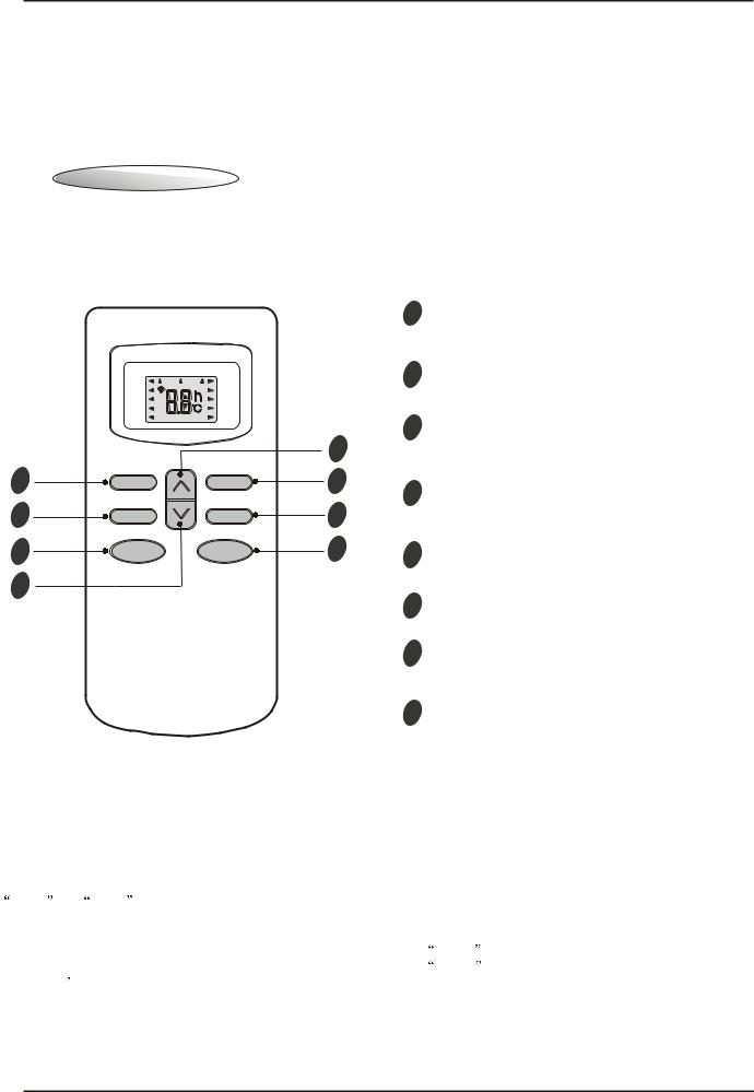
1Remote controller
5
2
8
4
Remote controller
The remote controller transmits signals to the system.
|
|
1 |
ON/OFF button |
|
|
|
Used to start and stop operation |
|
|
2 |
when pressed. |
FEEL |
AUTO |
TIMER button |
|
|
SLEEP TIMER ON TMIER OFF |
|
|
COOL |
HIGH |
|
Used to select TIMER operation. |
DRY |
MID |
|
|
FAN |
LOW |
|
|
HEAT |
SWING |
|
|
SLEEP |
FAN |
TIMER |
SWING |
MODE |
ON/OFF |
3
7
6
1
3 UP button (TOO COOL button)
Used to increase the set room temperature
and time.
4 DOWN button (TOO WARM button)
Used to decrease the set room temperature and time.
5 SLEEP button
Used to set or cancel sleep mode operation.
6 VANE control button
Used to adjust airflow direction.
7 FAN SPEED control button
Used to select the indoor fan motor speed:
Auto, High, Mid and Low.
8 MODE button
Used to select the type of operation mode: Feel,
Cooling, Dry, Fan and Heating(Only for Heat Pump).
Note: Each mode and relevant function will be further specified in following pages.
Remote Control
The remote controller is not preset as Cooling Only Air Conditioner or Heat Pump by manufacturer.
Each time after the remote controller replace batteries or is energized, the arrowhead will flash on the front of
Heat or |
Cool on LCD of the remote controller. |
|
|
User can preset the remote controller type depending on the air conditioner type you have purchased as |
|||
follows: |
|
|
|
Press any button when the arrowhead flashes on the front of |
Cool |
, Cooling Only is set. |
|
Press any button when the arrowhead flashes on the front of |
Heat |
, Heat Pump is set. |
|
If you don |
t press any button within 10 seconds, the remote controller is preset as Heat Pump automatically. |
||
Note :
If the air conditioner you purchased is a Cooling Only one, but you preset the remote controller as Heat Pump, it doesn t matter. But if the air conditioner you purchased is a Heat Pump one, and you preset the remote controller as Cooling Only, then you CAN NOT preset the Heating operation with the remote controller.
4
TCL Air Conditioner Service Manual
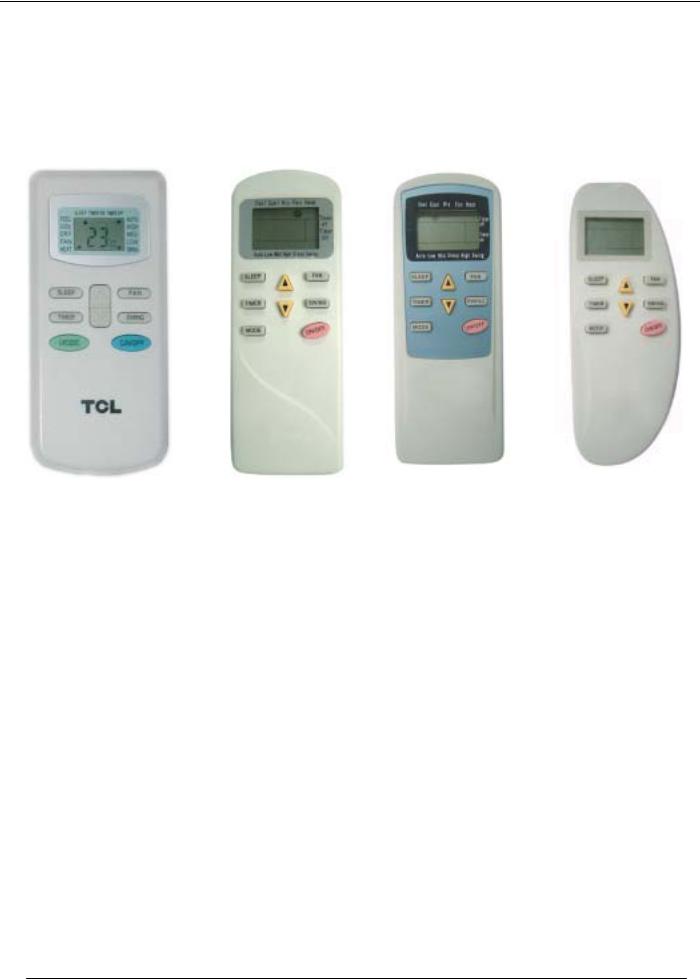
REMOTE CONTROLLER
The four types of remote controller is as follow:
GYKQ-05 |
GYKQ-10e (optional) |
GYKQ-11e (optional) |
GYKQ-12e (optional) |
Note: The function of remote controller above is the same.
5

TCL Air Conditioner Service Manual
Electronic Controller
1.Safety Control
(1)Time Delay Safety Control
3 minutes delay for compressor---The compressor is ceased for 3minutes to balance the pressure in the refrigeration cycle in order to protect the compressor.
2 minutes delay for 4-way valve---The 4-way valve is ceased for 2 minutes to prevent the refrigerant-gas abnormal noise when the HEATING operation is OFF or switch to the other operation mode.
(2) Indoor Pipe Temperature Sensor Frost Prevention Control
When the indoor pipe temperature sensor reads 32 or below for 5 minutes, the indoor pipe temperature sensor frost prevention control starts. The compressor and outdoor fan stop and indoor fan operates at high speed for 3 minutes. After that, if the indoor pipe temperature sensor reads less than 41 this control prolonged until the indoor pipe temperature sensor reads 41 or more.
(3)High Temperature Protection Control
During HEATING operation, the outdoor fan motor and compressor are controlled by the indoor pipe temperature to prevent the high temperature of compressor.
Outdoor fan OFF: when the indoor pipe temperature is ≥122 Outdoor fan ON: when the indoor pipe temperature is ≤118.4 Compressor OFF: when the indoor pipe temperature is ≥143.6 Compressor ON: when the indoor pipe temperature is ≤118.4
2.“I Feel” Mode Operation
(1)When the “I Feel” mode is selected, the operation mode and initial set temperature are determined by the initial room temperature at start-up of the operation except to turn off the air conditioner and operates it again.
(2)If the mode is change to “I Feel” mode from other mode, the “I Feel” mode doesn’t operate until compressor stop for more than 3 minutes.
Mode |
|
Initial room temperature |
Initial set temperature |
COOLING |
|
78.8 or more |
75.2 |
|
|||
DRY |
|
68 to 77 |
64.4 |
HEATING for Heat Pump Type |
|
Less than 68 |
73.4 |
FAN for Cooling Only Type |
|
|
|
|
|
|
|
In the “I Feel” mode , when the controller receives the up or down single of temperature, the set temperature can adjust by 33.8 upper or lower. The biggest you can adjust by 35.6 upper or lower.
3.“COOLING” Mode Operation
(1)When the COOLING mode is selected without setting temperature, the system will set the set temperature at
78.8 automatically with the AUTO FAN speed.
(2)When selecting the COOLING mode operation, the system will operate according to the setting by the remote controller and the operation is as following:
6

TCL Air Conditioner Service Manual
Room Temp. |
|
|
|
|
|
Set TEMP. 1.8 |
|
|
|
|
|
Set TEMP. 1.8 |
|
|
|
|
|
Time |
More than 2 min |
More than 2 min |
More than 2 min |
More than 2 min |
More than 2 min |
Indoor Fan |
Set Speed |
Set Speed |
Set Speed |
Set Speed |
Set Speed |
Compressor |
ON |
OFF |
ON |
OFF |
ON |
Outdoor Fan |
ON |
OFF |
ON |
OFF |
ON |
4.“DRY” Mode Operation
(1)The system for DRY operation used the same refrigerant circle as the cooling circle.
(2)When the system operates in DRY mode ,at first it operates in cooling mode at 60.8 or 64.4 for 3 minutes. And then, the system operates in cooling mode with low speed that regards the temperature of the room temperature sensor reads decrease 35.6 as the set temperature. During the course of this, the fan speed set operation is failing but the vane motor can be controlled.
5.“HEATING” Mode Operation (Only available for Heat Pump)
(1)When the HEATING mode is selected without setting temperature, the system will set the temperature at
73.4 automatically with the AUTO FAN speed.
(2)When selecting the HEATING mode operation, the system will operate according to the setting by the remote controller and the operation is as following:
Set Temp. 1.8 |
|
|
|
|
|
Set Temp. 1.8 |
|
|
|
|
|
Room Temp. |
|
|
|
|
|
Time |
More than 2 min |
More than 2 min |
More than 2 min |
More than 2 min |
More than 2 min |
Compressor |
ON |
OFF |
ON |
OFF |
ON |
Outdoor fan |
ON |
OFF |
ON |
OFF |
ON |
(3)In HEATING mode, the indoor fan motor speed is controlled by Cold Air Prevention Control.
(4)Cold Air Prevention Control
The function is intend to prevent cold air from being discharged when the heating operation starts or when defrosting.
The indoor fan speed will be controlled as following. The vane angle is at the angle C(100°).
raiseTemperature |
Set Speed |
Set Speed |
|
dropTemperature |
|
||||
|
Low Speed |
|
||
9 3 . 2 |
|
|||
|
|
|
|
|
|
Low Speed |
|
|
|
|
80.6 |
|
|
|
|
|
|
|
|
|
|
|
|
|
|
7 7 |
|
|
|
|
Stop the fan |
|
|
|
|
73.4 |
|
|
|
|
|
|
|
|
|
|
Stop the fan |
|
|
During the heating operation, if the compressor stops that it will adjust the indoor fan speed, after 30 seconds to stop the fan.
7
TCL Air Conditioner Service Manual
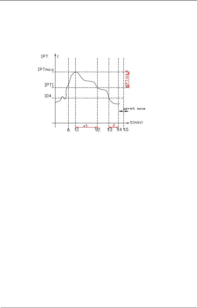
(5)Defrost
Defrosting of the outdoor heat exchange is controlled by the microprocessor with detection by the indoor pipe temperature sensor.
Defrost control type is according to the JC on the PCB whether is connected.
When the JC is connect on the PCB
When one of the conditions of A, Band C is satisfy, the defrosting operation stars. A. IPT--- indoor pipe temperature
) |
In the condition A, it must satisfy the conditions a), b)and c) then into defrosting operation.
a)IPT1 satisfy IPT1=IPTMAX IPT14.4
b)t5≥50minutes(the compressor cumulative operation time≥50 minutes, t5 is permitted move and lower than t1 too).
c)IPT 104 and keep 2 minutes.
According to the condition A enter the defrosting operation, the first defrosting operation time is 8 minutes; After defrosting operation one cycle, and then judge and regulate the defrosting operation time.
B.After the compressor cumulative operation time exceeds 120 minutes and the temperature of the IPT is less than 95 for 2 minutes. When the defrosting operation time on this condition exceeds 8 minutes, it will terminate.
C.After the compressor operates continuously for 20 minutes and the IPT is less than 73.4 or from the last time of defrosting operation is 50 minutes or more interval. When the defrosting operation
time on this condition exceeds 10 minutes, it will terminate.
When the JC isn’t connected on the PCB
When the conditions of a) or b) is satisfy, the defrosting operation starts.
a)Under the heating operation, the compressor cumulative operation time exceeds 50 minutes and the temperature of the outdoor pipe temperature sensor reads lower than 14.4
b)Under the heating operation, the compressor cumulative operation time exceeds 50 minutes, if the indoor pipe temperature sensor reads lower than 104 continuously for 2 minutes.
Note: If haven’t the outdoor pipe temperature sensor that uses the condition b) to defrost, against use the condition a).
Defrost terminating conditions
When the condition c) or d) is satisfy, the defrosting operation will terminate.
c)The outdoor defrost sensor reads 68 or more.
d)The defrosting time exceeds 10 minutes.
8
TCL Air Conditioner Service Manual
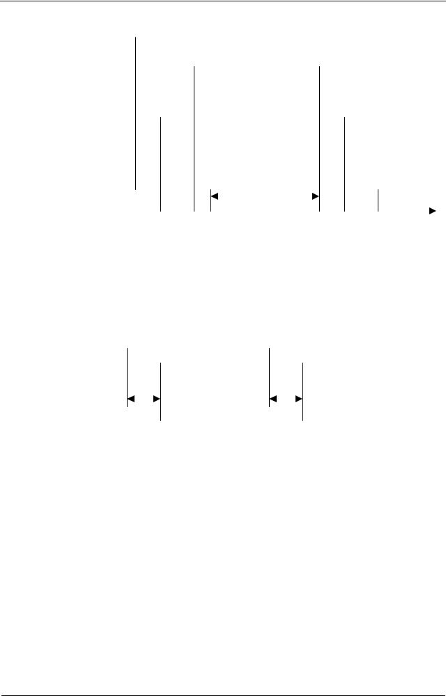
Defrosting time chart
Outdoor Fan |
ON |
OFF |
ON |
|
|
|
|
|
|
Revering Valve |
ON |
OFF |
|
ON |
|
|
|
|
|
|
|
|
|
|
|
|
|
|
|
|
|
Compressor Relay ON |
OFF |
|
|
ON |
|
OFF |
ON |
||||
|
|
|
|
|
|
|
|
|
|
|
|
|
|
|
|
|
|
|
|
|
|||
|
|
39S |
5S Defrost Count MAX 12min |
19S 15S |
|
t |
|
||||
6.“FAN” mode operation
The indoor fan motor always turns on at the set speed and the vane motor turns on at the set fettle.
7.4-way Valve control
HEATING ON
COOLING/DRY OFF
The 4-way valve reverses for 5 seconds right before start-up of the compressor as following chart:
COOLING/DRY TO HEATING |
|
HEATING TO COOLING/DRY |
|||||||||||
Compressor |
|
|
|
|
|
|
|
|
|
||||
|
|
|
|
|
|
|
|
|
|||||
|
|
|
|
|
|
|
|
|
|
|
|
|
|
4-way Valve |
|
|
|
|
|
|
|
|
|
|
|
||
|
5s |
|
|
2min |
|
|
|
||||||
|
|
|
|
|
|
|
|||||||
Outdoor Fan |
|
|
|||||||||||
|
|
|
|
|
|
|
|
|
|
|
|
||
|
|
|
|
|
|
|
|
|
|
||||
|
|
|
|
|
|
|
|
|
|
|
|
|
|
8.“SLEEP” mode
When the SLEEP button is pressed, the SLEEP mode is selected as following:
The indoor fan speed is set at the low speed, the power lamp and the sleep lamp is on, the temperature off after 5 minutes.
When selecting COOLING/DRY operation with SLEEP mode, the set temperature will be raised by 1.8 1 hour later and by 3.6 2 hour later.
When selecting HEATING operation with SLEEP mode, the set temperature will be dropped by 1.8 1 hour later and 3.6 2 hour later.
After the System operates in SLEEP mode for 8 hours, it will stop automatically.
9.Fan motor control
(1)Rotational frequency feedback control
The indoor fan motor is equipped with a rotational frequency sensor, and outputs signal to the microprocessor to feedback the rotational frequency. Comparing the current rotational frequency with the target rotational frequency, the microprocessor adjusts fan motor electric to make the current rotational frequency close to the target rotational frequency. With this control, when the fan speed is switched, the rotational frequency changes smoothly.
(2)When the rotational frequency feedback signal has not output for 5 seconds (or when the microprocessor can’t detect the signal for 5 seconds), the fan motor is regarded locked-up. Then the electric current to the fan
9
 Loading...