


281023BVE
Snapper 281023BVE, 2811523BV, 2812523BVE, 301352BVE, 281123BVE User Manual
...
Safety Instructions & Operator’s Manual for
REAR ENGINE RIDING MOWER
SERIES 23
MODELS
281123BV
2811523BV
281223BVE
2812523BVE
2813523BVE
301123BV
3011523BV
301223BVE
3012523BVE
3013523BVE
331323HVE
331523KVE
331623BVE
331723BVE
MODEL NUMBER EXPLANATION
33 15 23 K V E
CUTTING WIDTH ENGINE OPTIONS
ENGINE HP * ENGINE TYPE
SERIES DESIGNATION ENGINE MODEL
28
- 28” Cutting Deck
- 30” Cutting Deck
30
- 33” Cutting Deck
33
Thank you for buying a SNAPPER Product! Before operating your machine, read this manual carefully and pay
particular attention to the “IMPORTANT SAFETY INSTRUCTIONS” on Pages 2 thru 4. Remember that all power
equipment can be dangerous if used improperly. Also keep in mind that SAFETY requires careful use in
accordance with the operating instructions and common sense!
NOTE: Specifications are correct at time of printing and are subject to change without notice.
* Actual sustained equipment horsepower will likely be lower due to operating limitations and environmental factors. Please refer to
‘Engine Power Rating Information’ on Page 4 for further information.
BRIGGS & STRATTON YARD POWER PRODUCTS GROUP
COPYRIGHT © 2006, BRIGGS & STRATTON CORPORATION
MILWAUKEE, WI, USA. ALL RIGHTS RESERVED
11 – 11.0 HP Engine
115 – 11.5 HP Engine
12 – 12.0 HP Engine
125 – 12.5 HP Engine
13 – 13.0 HP Engine
- 13.5 HP Engine
135
15 – 15.0 HP Engine
16 – 16.0 HP Engine
17 – 17.0 HP Engine
- Series Designation B - Briggs Engine
23
K - Kohler Engine
H - Honda Engine
MANUAL No. 7101250 (I.R. 12/20/2006)
- Over Head Valve
V
- Electric Start
E
TP 100-5250-IR-RE-N

IMPORTANT SAFETY INSTRUCTIONS
WARNING: This powerful cutting machine is capable of amputating hands and feet and can throw objects that
can cause injury and damage! Failure to comply with the follow ing SAFETY instructions could result in serious
injury or death to the operator or other persons. The owner of the machine must understand these instructions
and must allow only persons who understand these instructions to operate machine. Each person operating
the machine must be of sound mind and body and must not be under the influence of any substance, which
might impair vision, dexterity or judgment. If you have any questions pertaining to your machine which your
dealer cannot answer to your satisfaction, call or write the Customer Service Department at SNAPPER,
McDonough, Georgia 30253. Phone: (1-800-935-2967).
PROTECTION FOR CHILDREN
Tragic accidents can occur if the operator is not alert to the
presence of children. Children are often attracted to the
machine and the mowing activity. Children who have been
given rides in the past may suddenly appear in the mowing
area for another ride and be run over or backed over by the
mach in e. Never assume that children will remain where you
last saw them.
1. KEEP children out of the mowing area and under the
watchful care of a responsible adult other than the
operator.
2. DO NOT allow children in yard when machine is
operated (even with the blade OFF).
3. DO NOT allow children or others to ride on machine,
attachments or towed equipment (even with the blades
OFF). They may fall and be seriously injured.
4. DO NOT allow pre-teenage children to operate
machine.
5. ALLOW only responsible adults & teenagers with
mature judgment under close adult supervision to
operate machine.
6. DO NOT operate blades in reverse. STOP BLADES.
LOOK and SEE behind and down for children, pets and
hazards before and while backing.
7. USE EXTRA CARE when approaching blind corners,
shrubs, trees, or other objects that may obscure vision.
PROTECTION AGAINST TIPOVERS
Slopes are a major factor related to loss-of-control and tipover accidents, which can result in severe injury or death.
All slopes require extra CAUTION. If you cannot back up
the slope or if you feel uneasy on the slope, DO NOT mow
it. Use extra care with grass catchers or other attachments;
these affect the handling and the stability of the machine.
1. DO NOT operate machine on slopes exceeding 15
degrees (27% grade).
2. Exercise EXTREME CAUTION on slopes above 10
degrees (18% grade). Turn blades OFF when traveling
uphill. Use a slow speed and avoid sudden or sharp
turns.
3. DO NOT operate machine back and forth across face
of slopes. Operate up and down. Practice on slopes
with blades off.
4. AVOID starting, stopping or turning on slopes. If
machine stops going uphill or tires lose traction, turn
blades OFF and back slowly straight down the slope.
PROTECTION AGAINST TIPOVERS
(Continued From Previous Column)
5. STAY ALERT for holes and other hidden hazards. Tall
grass can hide obstacles. Keep away from ditches,
washouts, culverts, fences and protruding objects.
6. KEEP A SAFE DISTANCE (at least 3 feet) away from
edge of ditches and other drop offs. The machine
could turn over if an edge caves in.
7. Always begin forward motion slowly and with caution.
8. Use w eights or a weighted load carrier in accordance
with instructions supplied with a grass catcher. DO
NOT operate machine on slopes exceeding 10 degrees
(18% grade) when equipped with grass catcher.
9. DO NOT put your foot on the ground to try to stabilize
the machine.
10. DO NOT operate machine on wet grass. Reduced
traction could cause sliding.
11. Chose a low enough speed setting so that you will not
have to stop or shift on a slope. Tires may lose traction
on slopes even though the brakes are functioning
properly.
12. DO NOT operate machine under any condition where
traction, steering or stability is doubtful.
13. Always keep the machine in gear when going down
slopes. DO NOT shift to neutral (or actuate hydro roll
release) and coast downhill.
PREPARATION
1. Read, understand, and follow instructions and
warnings in this manual and on the machine, engine
and attachments. Know the controls and the proper
use of the machine before starting.
2. Only mature, responsible persons shall operate the
machine and only after proper instruction.
3. Data indicates that operators age 60 and above, are
involved in a large percentage of mower-related
injuries. These operators should evaluate their ability
to operate the mower safely enough to protect
themselves and others from serious injury.
4. Handle fuel with extra care. Fuels are flammable and
vapors are explosive. Use only an approved fuel
container. DO NOT remove fuel cap or add fuel with
engine running. Add fuel outdoors only with engine
stopped and cool. Clean spilled fuel from machine. DO
NOT smoke.
5. Practice operation of machine with BLADES OFF to
learn controls and develop skills.
2

IMPORTANT SAFETY INSTRUCTIONS
PREPARATION
(Continued From Previous Page)
6. Check the area to be mowed and remove all objects
such as toys, wire, rocks, limbs and other objects
that could cause injury if thrown by blade or
interfere with mowing.
7. Keep people and pets out of mowing area.
Immediately STOP blades, STOP engine, and
STOP machine if anyone enters the area.
8. Check shields, deflectors, switches, blade
controls and other safety devices frequently for
proper operation and location.
9. Make sure all safety decals are clearly legible.
Replace if damaged.
10. Protect yourself when mow ing and wear safety
glasses, long pants and substantial footwear.
11. Know how to STOP blades and engine quickly
in preparation for emergencies.
12. Use extra care when loading or unloading the
machine into a trailer or truck.
13. Check grass catcher components frequently for
signs of wear or deterioration and replace as
needed to prevent injury from thrown objects
going through weak or worn spots.
SAFE HANDLING OF GASOLINE
To avoid personal injury or property damage, use
extreme care in handling gasoline. Gasoline is
extremely flammable and the vapors are explosive
1. Extinguish all cigarettes, cigars, pipes and
other sources of ignition.
2. Use only an approved fuel container.
3. DO NOT remove fuel cap or add fuel with the
engine running. Allow the engine to cool before
refueling.
4. DO NOT refuel the machine indoors.
5. DO NOT store the machine or fuel container
inside where there is an open flame, spark or
pilot light such as on a water heater or other
appliances.
6. DO NOT fill fuel containers inside a vehicle or
on a truck or trailer bed with a plastic liner.
Always place the containers on the ground
away from the vehicle before filling.
7. Remove gas-powered equipment from the
vehicle or trailer and refuel it on the ground. If
this is not possible, then refuel equipment
using a portable container, rather than a
gasoline dispenser nozzle.
8. DO NOT start gas powered equipment in
enclosed vehicles or trailers.
9. Keep the nozzle in contact with the rim of the
fuel tank or container opening at all times until
fueling is complete. DO NOT use a nozzle lockopen device
10. If fuel is spilled on clothing, change clothing
immediately.
11. Never overfill a fuel tank. Replace fuel cap and
tighten securely.
OPERATION
1. Mount and dismount machine from left side.
Keep clear of discharge opening at all times.
2. Start engine from operator's seat, if possible.
Make sure blades are OFF and parking brake is
set.
3. DO NOT leave machine with engine running.
STOP engine, STOP blades, SET brake, and
Remove key before leaving operators position
of any reason.
4. DO NOT operate machine unless properly
seated with feet on feet rests or pedal(s).
5. STOP BLADES and ENGINE and make sure
blades have stopped before removing grass
catcher or unclogging mower to prevent loss of
fingers or hand.
6. Blades must be OFF except when cutting grass.
Set blades in highest position when mowing
over rough ground.
7. Keep hands and feet away from rotating blades
underneath deck. DO NOT place foot on ground
while BLADES are ON or machine is in motion.
8. DO NOT operate machine without entire grass
catcher or guards in place and working. DO
NOT point discharge at people, passing cars,
windows or doors.
9. Slow down before turning.
10. Watch out for traffic when near or crossing
roadways.
11. STOP engine immediately after striking an
obstruction. Inspect machine and repair
damage before resuming operation.
12. Operate machine only in daylight or with good
artificial light.
13. Move joystick (if equipped) SLOWLY to
maintain control during speed and directional
changes.
14. Exercise CAUTION when pulling loads. Limit
loads to those you can safely control and attach
loads to hitch plate as specified with SNAPPER
attachment instructions.
15. On slopes, the weight of the towed equipment
may cause loss of traction and loss of control.
When towing, travel slowly and allow extra
distance to stop.
16. DO NOT operate engine in enclosed areas.
Engine exhaust gases contain carbon
monoxide, a deadly poison.
17. DO NOT discharge material against a wall or
obstruction. Material may ricochet back
towards the operator.
18. Only use accessories approved by the
manufacturer. See manufacturer’s instructions
for proper operation and installation of
accessories.
3

IMPORTANT SAFETY INSTRUCTIONS
TOWING
1. Tow only with a machine that has a hitch
designed for towing. DO NOT attach towed
equipment except at the hitch point.
2. Follow the manufacturer’s recommendation for
weight limits for towed equipment and towing
on slopes.
3. DO NOT allow children or others on towed
equipment.
4. On slopes, the w eight of the towed equipment
may cause loss of traction and loss of control.
5. Travel slowly and allow extra distance to stop.
MAINTENANCE
1. DO NOT store machine or fuel container inside
where fumes may reach an open flame, spark or
pilot light such as in a water heater, furnace,
clothes dryer or other gas appliance. Allow
engine to cool before storing machine in an
enclosure. Store fuel container out of the reach
of children in a well ventilated, unoccupied
building.
2. Keep engine free of grass, leaves or excess
grease to reduce fire hazard and engine
overheating.
3. When draining fuel tank, drain fuel into an
approved container outdoors and away from
open flame.
4. Check brakes frequently; adjust, repair or
replace as needed.
5. Keep all bolts, nuts and screw s properly tight.
Check that all cotter pins are in proper position.
Engine Power Rating Information
The gross power rating labels for individual gas engine models meet or exceed SAE (Society of Automotive
Engineers) code J1940 (Small Engine Power & Torque Rating Procedure) and rating performance has been
obtained and corrected in accordance with SAE J1995 (Revision 2002-05). Actual gross engine power may be
lower and is affected by, but not limited to, ambient operating conditions and engine to engine variability. Given
both the wide array of products on which engines are placed, and the variety of environmental issues applicable
to operating the equipment, the gas engine will not develop the rated gross power when used in a given piece of
power equipment (actual “on-site” or net horsepower). This difference is due to a variety of factors including, but
not limited to, accessories (air cleaner, exhaust, charging, cooling, carburetor, fuel pump, etc.), application
limitations, ambient operating conditions (temperature, humidity, altitude), and engine to engine variability.
This manual contains safety information to make you aware of the hazards and
risks associated with the machine and how to avoid them. This machine is
designed and intended to be used and maintained according to the manual for
finish cutting of established lawns and is not intended for any other purpose. It
is important that you read and understand these instructions thoroughly before
attempting to start or operate this equipment.
Statement of Usage
MAINTENANCE
(Continued From Previous Column)
6. Always provide adequate ventilation when
running engine. Exhaust gases contain carbon
monoxide, an odorless and deadly poison.
7. Disconnect negative (black) cable from battery
before performing maintenance or service.
Cranking engine could cause injury.
8. DO NOT work under machine without safety
blocks.
9. Service engine and make adjustments only
when engine is stopped. Remove spark plug
wire(s) from spark plug(s) and secure wire(s)
away from spark plug(s).
10. DO NOT change engine governor speed
settings or overspeed engine.
11. Lubricate machine at intervals specified in
manual to prevent controls from binding.
12. Mower blades are sharp and can cut. Wrap the
blades or wear heavy leather gloves and use
CAUTION when handling them.
13. DO NOT test for spark by grounding spark plug
next to spark plug hole; spark plug could ignite
gas exiting engine.
14. Have machine serviced by an authorized
SNAPPER dealer at least once a year and have
the dealer install any new safety devices.
15. Maintain or replace safety and instruction labels
as necessary.
16. Use only genuine SNAPPER replacement parts
to assure that original standards are
maintained.
4

TABLE OF CONTENTS
IMPORTANT SAFETY INSTRUCTIONS ........................................................................2-4
TABLE OF CONTENTS ..................................................................................................... 5
SECTION 1 - FAMILIARIZATION......................................................................................6
SECTION 2 - OPERATING INSTRUCTIONS...............................................................7-13
Pre-start Checklist......................................................................................................... 7
Operator’s Seat Adjustment.........................................................................................7
Starting & Stopping Engine, Blade & Wheel Drive................................................8-11
Starting & Stopping Mower Blades.......................................................................10-11
Starting & Stopping Wheel Drive ..........................................................................10-11
Parking Brake............................................................................................................... 12
Cutting Height Adjustment.........................................................................................12
Reverse Lockout Mechanism.....................................................................................13
SECTION 3 - MAINTENANCE INSTRUCTIONS........................................................14-19
Service – After First 5 Hours .................................................................................14-16
Change Engine Oil....................................................................................................14
Service Engine Air Cleaner......................................................................................14
Check Mower Blade .................................................................................................14
Check Blade Drive Belt............................................................................................15
Blade Brake...............................................................................................................15
Service Brake / Park Brake......................................................................................15
Check Interlock System...........................................................................................16
Reverse Lockout Mechanism..................................................................................16
Lubrication – Grease Fittings – Overview .............................................................16
Service – Every 25 Operating Hours.....................................................................16-18
Check Engine............................................................................................................16
Battery Fluid Level ...................................................................................................17
Mower Deck Levelness............................................................................................17
Clean Mower Deck....................................................................................................17
Mower Blade Spindle – Lubrication .......................................................................17
Mower Deck Linkage – Lubrication........................................................................17
Front Wheel Bearing – Lubrication.........................................................................17
Shift Lever – Lubrication ......................................................................................... 17
Rear Axle Bearing – Lubrication.............................................................................18
Differential / Chain Case – Lubrication .................................................................. 18
Service – Annually.......................................................................................................18
Engine........................................................................................................................19
Fuel Filter...................................................................................................................19
Every Two Years..........................................................................................................19
Storage – Out of Season.............................................................................................19
Removing Fuel Tank....................................................................................................19
SECTION 4- ADJUSTMENTS AND REPAIR .............................................................20-28
Engine Adjustments & Repair....................................................................................20
Mower Deck & Component Adjustments..................................................................20
Blade Brake Adjustment.............................................................................................20
Mower Deck Adjustment (Side to Side Levelness) .................................................. 21
Mower Deck Adjustment (Front to Rear Levelness)................................................21
Mower Drive Belt Adjustment – 28” & 30” Decks.....................................................22
Rear Engine Rider Drive Components ......................................................................23
Service Brake/Park Brake Adjustment......................................................................23
Mower Blade Replacement.........................................................................................24
Blade Sharpening ........................................................................................................ 24
Mower Drive Belt Removal/Replacement – 28” 30” & 33” Decks........................... 25
Battery Removal, Replacement, Service..............................................................26-28
ACCESSORIES............................................................................................................. 28
TROUBLESHOOTING ................................................................................................29-30
MAINTENANCE SCHEDULE...........................................................................................31
MAINTENANCE/REPLACEMENT PARTS......................................................................32
WARRANTY.....................................................................................................................33
PRIMARY MAINTENANCE.........................................................................................34-37
PRODUCT REGISTRATION FORM ................................................................................ 38
5
Section 1 - FAMILIARIZATION
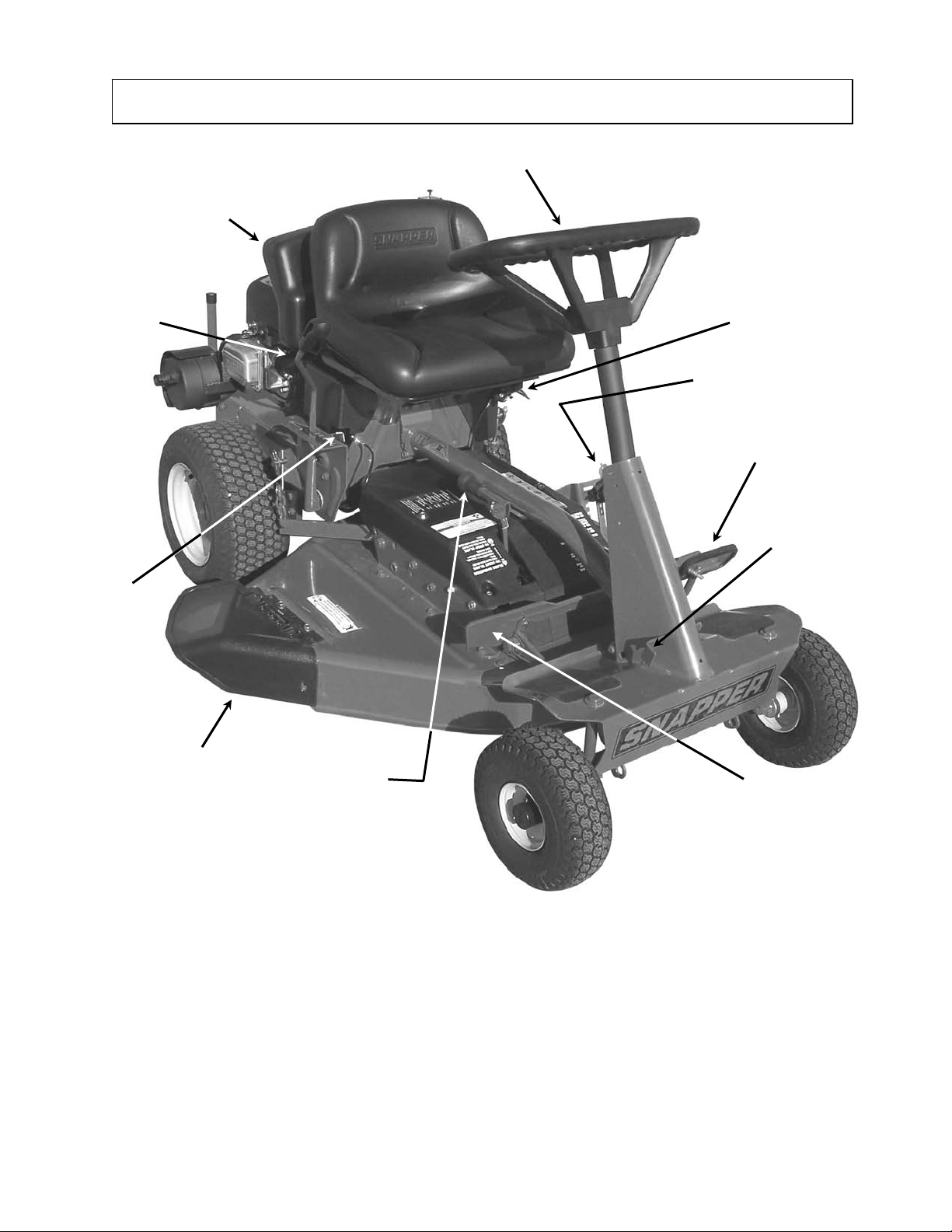
IMPORTANT: The figures and illustrations in this manual are provided for reference only and may differ from your
specific model. Contact your Snapper dealer if you have questions.
FUEL TANK
STEERING
WHEEL
TRANSMISSION
SHIFT LEVER
OVERRIDE
CONTROL
ENGINE SPEED
CONTROL (HIDDEN)
IGNITION
SWITCH
CLUTCH/BRAKE
PARK BRAKE
LATCH
DISCHARGE
DEFLECTOR
BLADE LEVER
1.1 INTRODUCTION
This manual has been prepared for the operator’s of the
SNAPPER Rear Engine Rider. Its purpose, aside from
recommending standard operating procedures and
routine service requirements, is to promote SAFETY
through the use of accepted operating practices. Read,
Understand and Follow the IMPORTANT SAFETY
INSTRUCTIONS on Pages 2 thru 4 of this manual and
All SAFETY messages on the Rear Engine Rider and its
attachments before operating.
BLADE PEDALS
FIGURE 1.1
1.2 NOMENCLATURE
The nomenclature drawing above, Figure 1.1, shows the
essential parts of the SNAPPER Rear Engine Rider. It is
recommended that all operators of this equipment
become thoroughly familiar with the controls,
components, and operation of this machine before
operating. Specific details involving the engine are
found in the separate engine owner’s manual. Study
these manuals before operating and keep both handy
for future reference.
6
Section 2 - OPERATING INSTRUCTIONS
)
2.1 PRE-START CHECK LIST
Make the following checks and perform the service
required before each start-up.
2.1.1. Check tires and add or release air as needed
to bring pressure to 12 PSI in front and 12 PSI in rear
tires.
2.1.2. Check guards, deflectors and covers to make
sure all are in place and securely tightened.
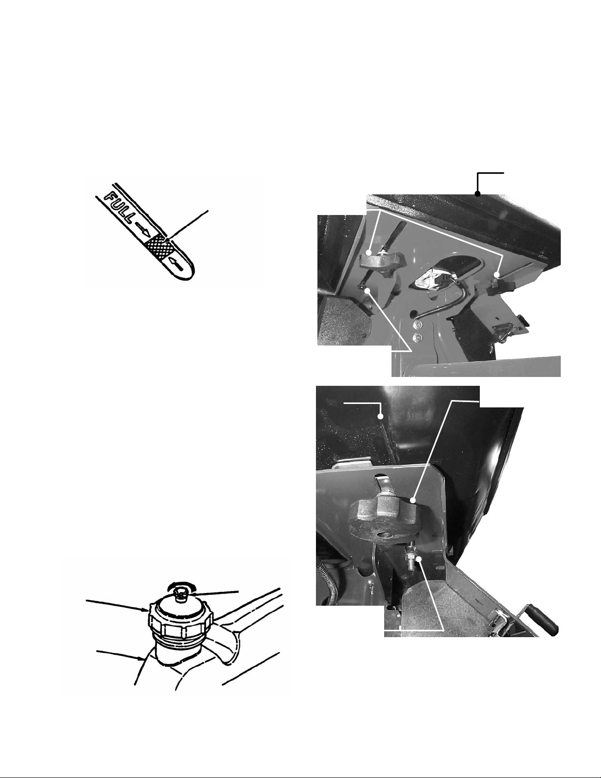
2.1.3. Check engine oil and add oil as needed to
bring level up to the FULL mark. Refer to engine
owner’s manual for oil specifications. See Figure 2.1.
SAFE LEVEL
AREA
FIGURE 2.1
2.1.4. Adjust seat as needed to most comfortable
position. Refer to Section “OPERATOR’S SEAT
ADJUSTMENT”.
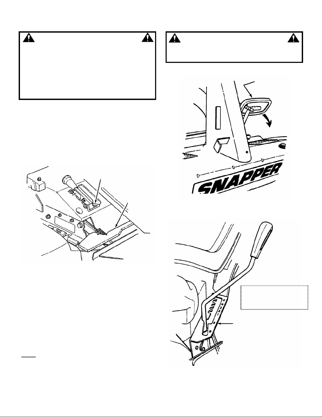
2.1.5. Check blade control to insure it works freely.
If blade pedals are depressed, blade lever can be
moved manually from “ON” to “OFF” to stop
blade.
2.1.6. Check Reverse Lockout Mechanism. With
blade pedals depressed, shift lever must not go into
reverse.
2.1.7. Clean exterior surfaces of cutting deck and
engine of any accumulation of dirt, grass, oil, etc.
Keep engine air intake screen and cooling fins clear
at all times.
2.1.8. Add fuel to tank after pushing the Rear Engine
Rider outside where fumes can dissipate. Make sure
fuel filler cap is tight and vent is open after refueling.
Refer to engine owner’s manual for fuel
specifications. See Figure 2.2.
OPEN
FUEL
FILLER
CAP
FUEL
TANK
VENT
FIGURE 2.2
2.2 OPERATOR’S SEAT ADJUSTMENT
2.2.1. FRONT TO REAR ADJUSTMENT
1. With the engine stopped, loosen the two adjusting
knobs and move seat to desired position. After
adjustment, tighten knobs securely. If seat does not
move after loosening knobs, it may be necessary to
loosen the 5/16” patch lock screws or hex nuts
located at the rear of the seat. See Figure 2.3.
ADJUSTING
KNOBS
5/16” PATCH LOCK
SCREWS (DO NOT
OVERTIGHTEN
OPERATOR’S
SEAT
HEX NUTS
(DO NOT
OVERTIGHTEN)
7
OPERATOR’S
SEAT
ADJUSTING
KNOBS
FIGURE 2.3
Section 2 - OPERATING INSTRUCTIONS
2.3 STARTING & OPERATION
2.3.1. ENGINE (ELECTRIC START)
IMPORTANT: When the ignition key is turned to
“START”, the engine will turn over, but will
unless the Clutch/Brake pedal is pressed all the way
down, the Blade Lever is in the “OFF” position (See
Figure 2.5). The operator should be in the seat. Start
engine as follows:
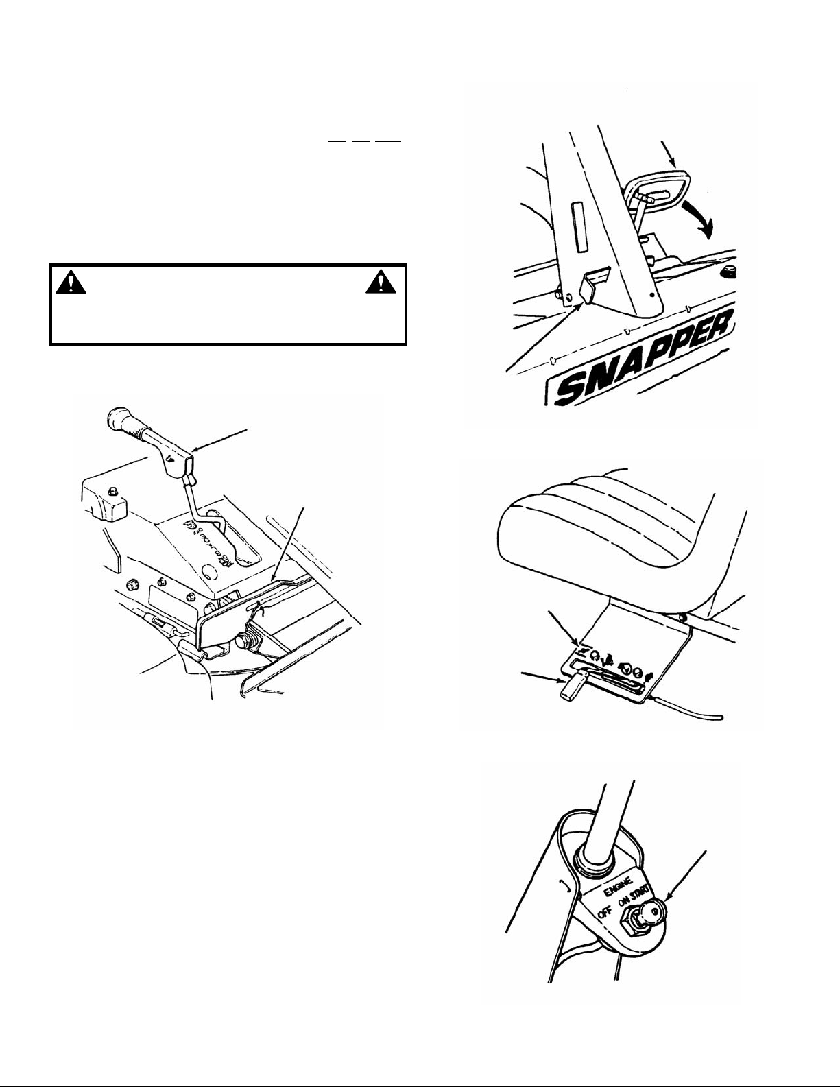
1. Move transmission shift lever to (N) Neutral
position. DO NOT start engine with transmission
shift lever in a drive position.
WARNING
It is possible to start engine with transmission shift
lever in a drive position. Follow starting instructions
carefully.
2. Make certain the Blade Lever is in the “OFF”
position. See Figure 2.4.
BLADE LEVER IN
“OFF” POSITION
not start
PARKING
BRAKE
LATCH
TO START ENGINE,
PUSH CLUTCH/BRAKE
PEDAL ALL THE WAY
DOWN
FIGURE 2.5
RELEASE BLADE
PEDALS
FIGURE 2.4
3. Press Clutch/Brake Pedal all
the way down and
hold while starting engine. See Figure 2.5.
4. Open vent on fuel filler cap by turning
counterclockwise. IMPORTANT: Failure to open
vent on the fuel filler cap can cause engine to stall.
See Figure 2.2.
5. Move engine speed control to the choke position
to start a cold engine. See Figure 2.6.
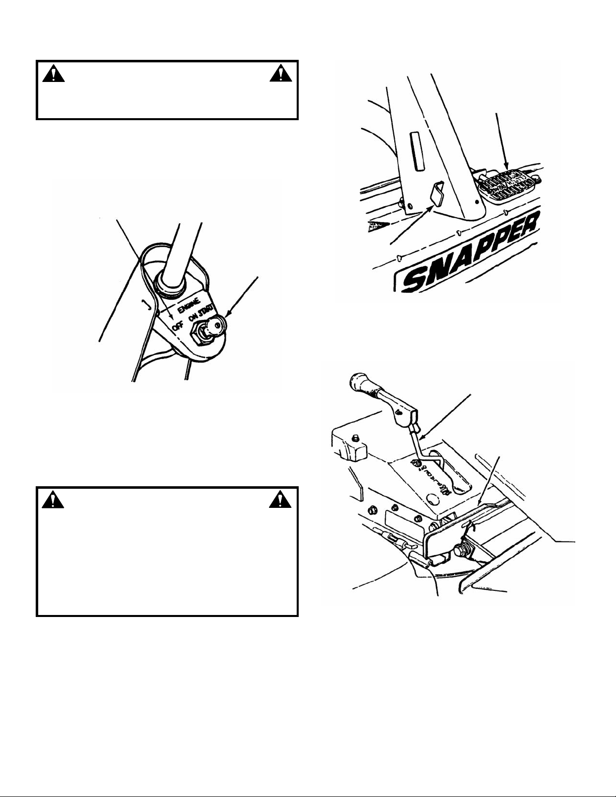
6. Turn key to the “START” position until engine
starts. See Figure 2.7. NOTE: If after 5 seconds of
cranking the engine and it does not start, release the
key, make sure the Clutch/Brake Pedal is fully
depressed and attempt starting again after waiting for
approximately 20 seconds.
7. After engine starts, move engine speed control to
the “FAST” position, allow a brief warm-up until
engine runs smooth.
CHOKE
POSITION
ENGINE
SPEED
CONTROL
FIGURE 2.6
KEY
FIGURE 2.7
(Continued on Next Page)
8
Section 2 - OPERATING INSTRUCTIONS
2.3 STARTING & OPERATION
2.3.1. ENGINE (ELECTRIC START) (Continued)
8. Should the battery be too weak to start the engine,
refer to Section “ENGINE (MANUAL START)” to
manually start the electric start engines.
9. On Model 3314522BVE, the engine is equipped
with a fuel shut-off solenoid. If the battery is dead, the
engine can be started with the recoil back-up starter if
the throttle control is in the choke position (HOT
engine or COLD engine).
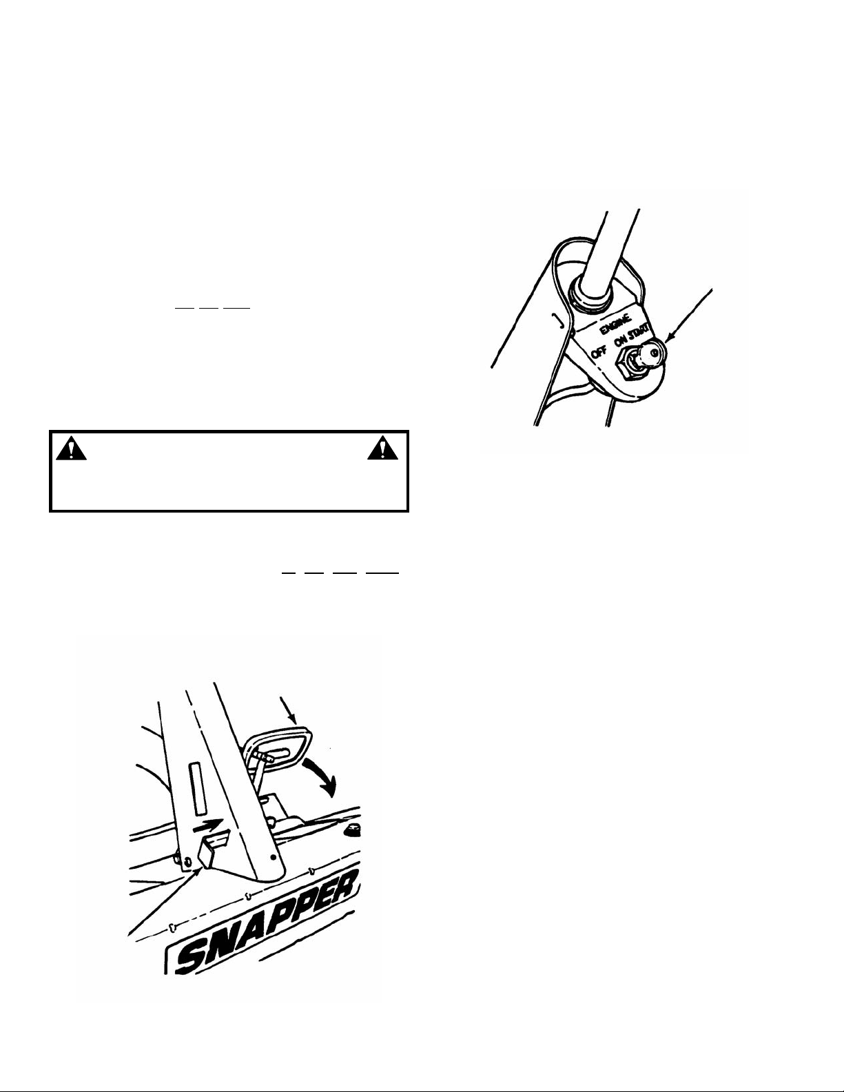
2.3.2. ENGINE (MANUAL START)
IMPORTANT: When the ignition key is turned to
“ON”, and the recoil handle is pulled, the engine will
turn over, but will
not start unless the Clutch/Brake
Pedal is pressed all the way down with Parking
Brake engaged (See Figure 2.8) and the Blade
Lever is in the “Off” position (See Figure 2.4). Start
engine as follows:
1. Move transmission shift lever to (N) Neutral
position. DO NOT start engine with transmission shift
lever in a drive position.
4. Open vent on fuel filler cap by turning
counterclockwise. NOTE: Failure to open vent on
the fuel filler cap can cause engine to stall.
5. Move engine speed control to the choke position
to start a cold engine. See Figure 2.6.
6. Turn key to “ON” position. See Figure 2.9.
KEY
WARNING
It is possible to start engine with transmission shift
lever in a drive position. Follow starting instructions
carefully.
2. Make certain the Blade Lever is in the “OFF”
position. See Figure 2.4.
3. Press Clutch/Brake Pedal all
move Parking Brake Latch over and release the
Clutch/Brake Pedal to set Parking Brake. See
Figure 2.8.
TO START ENGINE,
PUSH CLUTCH/BRAKE
PEDAL ALL THE DOWN
MOVE
PARKING
BRAKE
LATCH
OVER
FIGURE 2.8
the way down,
FIGURE 2.9
7. Pull starter rope with a smooth, even motion
until engine starts. Always guide the starter rope
back into the recoil housing. Never allow rope to
snap back. After Engine starts, move engine speed
control to the “FAST” position.
8. Allow a brief warm-up until engine runs smooth.
9
Section 2 - OPERATING INSTRUCTIONS
WARNING
Once blade is disengaged, it should come to a
complete stop in 3 seconds or less. If the blade
continues to rotate after 3 seconds, the blade brake
must be adjusted. Refer to Section “BLADE BRAKE
ADJUSTMENT” for adjustment procedures or return
machine to an authorized SNAPPER dealer for
adjustment. DO NOT CONTINUE to operate machine
until blade brake is adjusted and functioning
properly.
2.3 STARTING & OPERATION
2.3.3. MOWER BLADE
1. With engine running, move engine speed control
to the “FAST” position.
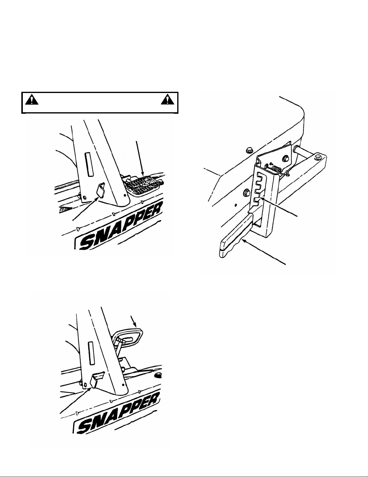
2. Move blade lever forward to the “ON” position,
then depress blade pedals to hold blade lever in the
“ON” position. See Figure 2.10.
BLADE LEVER SHOWN IN
“ON” POSITION
BLADE PEDAL
SHOWN
DEPRESSED
WARNING
DO NOT operate blades in reverse. STOP BLADES.
LOOK and SEE behind and down for children, pets
and hazards before and while backing.
DEPRESS
CLUTCH/BRAKE
PEDAL
FIGURE 2.11
FIGURE 2.10
2.3.4. WHEEL DRIVE
1. With engine running, adjust engine speed
control to “FAST” position.
2. Depress clutch/brake pedal. See Figure 2.11.
3. Place transmission shift lever in notch for first
speed. See Figure 2.12.
4. Release clutch/brake pedal to begin desired
ground speed.
5. During forward motion, the transmission shift
lever may be placed in any desired forward speed
without depressing the clutch/brake pedal.
: For best cutting results, move the transmission
NOTE
shift lever into a slow forward speed and the engine
speed control to a fast position. This combination will
allow the mower blades to lift the grass while cutting
smoothly and evenly.
THERE ARE FIVE
DIFFERENT FORWARD
GROUND SPEEDS AND ONE
REVERSE GROUND SPEED
SHIFT LEVER SHOWN IN
NEUTRAL POSITION
FIGURE 2.12
10
Section 2 - OPERATING INSTRUCTIONS
WARNING
DO NOT leave the machine with the engine running.
STOP Blade. STOP engine. Shift to neutral and
engage park brake. Remove key.
2.4 STOPPING - ENGINE, WHEEL DRIVE, BLADE
2.4.1. ENGINE
1. Stop engine by turning key to the “OFF” position.
See Figure 2.13.
TURN TO
“OFF”
POSITION
KEY
TO APPLY
BRAKES, PUSH
CLUTCH/BRAKE
PEDAL ALL THE
WAY DOWN
PARK BRAKE
LATCH SHOWN
ENGAGED
CLUTCH/BRAKE
PEDAL
FIGURE 2.13
2.4.2. WHEEL DRIVE
1. Stop motion of Rear Engine Rider by pushing
clutch/brake pedal all the way “DOWN” to apply
brake. See Figure 2.14.
WARNING
Once blade is disengaged, it should come to a
complete stop in 3 seconds or less. If the blade
continues to rotate after 3 seconds, the blade brake
must be adjusted. Refer to Section “BLADE BRAKE
ADJUSTMENT” for adjustment procedures or return
machine to an authorized SNAPPER dealer for
adjustment. DO NOT CONTINUE to operate machine
until blade brake is adjusted and functioning
properly.
2.4.3. MOWER BLADE
1. Stop mower blade by releasing blade pedals or
moving blade lever rearward to the “OFF” position.
See Figure 2.15.
FIGURE 2.14
BLADE LEVER IN “OFF”
POSITION
RELEASE BLADE
PEDALS
FIGURE 2.15
11
Section 2 - OPERATING INSTRUCTIONS
2.4 STOPPING - ENGINE, WHEEL DRIVE, BLADE
2.4.4. PARK BRAKE
1. Engage park brake by pushing clutch/brake pedal
“DOWN” and moving the park brake latch to the
“ENGAGED” position. While holding the park brake
latch “ENGAGED”, release clutch/brake pedal to set
park brake. See Figure 2.16.
WARNING
DO NOT park the machine on slopes.
CLUTCH/BRAKE
PEDAL
2.5. CUTTING HEIGHT ADJUSTMENT
1. Adjust cutting height as desired to any one of
five positions using deck lift lever. Move deck lift
lever up or down to desired cutting height and then
move over to secure in the height of cut notch.
See Figure 2.18.
PARK BRAKE
LATCH SHOWN
ENGAGED
FIGURE 2.16
2. Release park brake by pushing down on the
clutch/brake pedal, parking brake latch will move to
the “OFF” position unassisted. See Figure 2.17.
CLUTCH/BRAKE
PEDAL SHOWN
DISENGAGED
PARK BRAKE
LATCH SHOWN
IN “OFF”
POSITION
FIGURE 2.17
HEIGHT OF CUT
NOTCHES
DECK LIFT
LEVER
FIGURE 2.18
12
 Loading...