


Safety Instructions & Operator’s Manual for
MID MOUNT Z-RIDER
ZERO TURNING
HYDRO DRIVE
SERIES 1
MODELS
NZM19481KWV
NZM21521KWV
NZM25611KWV
NZM27611KH
MODEL NUMBER EXPLANATION
|
|
|
|
|
N |
Z |
M |
|
19 |
|
48 |
1 |
KWV |
|
|
|
||||||||||
MODEL DESIGNATION |
|
|
|
|
|
|
|
|
|
|
|
|
|
|
|
|
|
|
|
|
ENGINE TYPE |
|||||
|
|
|
|
|
|
|
|
|
|
|
|
|
|
|
|
|
|
|||||||||
|
|
|
|
|
|
|
|
|
|
|
|
|
|
|
|
|
|
|
||||||||
DRIVE SYSTEM TYPE |
|
|
|
|
|
|
|
|
|
|
|
|
|
|
|
|
|
|
|
|
SERIES DESIGNATION |
|||||
|
|
|
|
|
|
|
|
|
|
|
|
|
|
|
|
|
|
|
|
|||||||
MOWER ORIENTATION |
|
|
|
|
|
|
|
|
|
|
|
|
|
|
|
|
|
|
|
MOWER DECK SIZE |
||||||
|
|
|
|
|
|
|
|
|
|
|
|
|
|
|
|
|
|
|
||||||||
ENGINE HP |
|
|
|
|
|
|
|
|
|
|
|
|
|
|
|
|
|
|
|
|
|
|
|
|||
|
|
|
|
|
|
|
|
POWER UNIT |
|
|
|
|
|
|
|
|
|
|
|
|||||||
|
|
|
|
|
|
|
|
|
|
|
|
|
|
|
|
|
|
|
|
|
|
|
||||
N – Model Designation |
|
19.0 – Engine Horse Power |
|
48 – 48” Mower Width |
1 – Series Designation |
|||||||||||||||||||||
Z – Zero Turning – Hydro Drive |
|
21.0 |
-- Engine Horse Power |
|
52 – 52” Mower Width |
KW – Kawasaki Engine |
||||||||||||||||||||
M – Mid Mount Mower |
|
25.0 |
– Engine Horse Power |
|
61 – 61” Mower Width |
KH – Kohler Engine |
||||||||||||||||||||
|
|
|
|
|
|
|
|
27.0 |
– Engine Horse Power |
|
|
|
|
|
|
|
|
V – Over Head Valve |
||||||||
Thank you for buying a SNAPPER Product! Before operating your machine, read this manual carefully and pay particular attention to the “IMPORTANT SAFETY INSTRUCTIONS” on Pages 2 - 4. Remember that all power equipment can be dangerous if used improperly. Also keep in mind that SAFETY requires careful use in accordance with the operating instructions and common sense!
COPYRIGHT © 2003 SNAPPER PRODUCTS INC. ALL RIGHTS RESERVED
MANUAL No. 7-1762 (I.R. 11/25/03)

IMPORTANT SAFETY INSTRUCTIONS
WARNING: This powerful cutting machine is capable of amputating hands and feet and can throw objects that can cause injury and damage! Failure to comply with the following SAFETY instructions could result in serious injury or death to the operator or other persons. The owner of the machine must understand these instructions and must allow only persons who understand these instructions to operate machine. Each person operating the machine must be of sound mind and body and must not be under the influence of any substance, which might impair vision, dexterity or judgment. If you have any questions pertaining to your machine which your dealer cannot answer to your satisfaction, call or write the Customer Service Department at SNAPPER, McDonough, Georgia 30253. Phone: (1-800-935-2967).
PROTECTION FOR CHILDREN
Tragic accidents can occur if the operator is not alert to the presence of children. Children are often attracted to the machine and the mowing activity. Never assume that children will remain where you last saw them.
1.KEEP children out of the mowing area and under the watchful care of a responsible adult.
2.DO NOT allow children in yard when machine is operated (even with the blades OFF).
3.DO NOT allow children or others to ride on machine, attachments or towed equipment (even with the blades OFF). They may fall and be seriously injured.
4.DO NOT allow pre-teenage children to operate machine. Local regulations may restrict the age of the operator.
5.ALLOW only adults or responsible teenagers with mature judgment under close adult supervision to operate machine.
6.DO NOT operate blades in reverse. STOP BLADES. LOOK and SEE behind and down for children, pets and hazards before and while backing.
7.USE EXTRA CARE when approaching blind corners, shrubs, trees, or other objects that may obscure vision.
PROTECTION AGAINST TIPOVERS
Slopes are a major factor related to loss-of-control and tip-over accidents, which can result in severe injury or death. All slopes require extra CAUTION. If you cannot back up the slope or if you feel uneasy on the slope, DO NOT mow it. Use extra care with grass catchers or other attachments; these and turf conditions affect the handling and the stability of the machine.
1.DO NOT operate machine on slopes exceeding 15 degrees (27% grade).
2.Exercise EXTREME CAUTION on slopes above 10 degrees (18% grade). Turn blades OFF when traveling uphill. Use a slow speed and avoid sudden or sharp turns.
3.DO NOT operate machine back and forth across face of slopes. Operate up and down. Practice on slopes with blades off.
PROTECTION AGAINST TIPOVERS
(Continued From Previous Column)
4.AVOID starting, stopping or turning on slopes. If machine stops going uphill or tires lose traction, turn blades OFF and back slowly straight down the slope.
5.STAY ALERT for holes and other hidden hazards. Tall grass can hide obstacles. Keep away from ditches, washouts, culverts, fences and protruding objects.
6.DO NOT operate machine near drop offs, ditches, embankments, washouts, culverts, fences and protruding objects. KEEP A SAFE DISTANCE (at least 3 feet) away from edge of ditches and other drop offs. The machine could turn over if an edge caves in.
7.Always begin forward motion slowly and with caution.
8.Use weights or a weighted load carrier in accordance with instructions supplied with a grass catcher. DO NOT operate machine on slopes exceeding 10 degrees (18% grade) when equipped with grass catcher.
9.DO NOT put your foot on the ground to try to stabilize the machine.
10.DO NOT operate machine on wet grass. Reduced traction could cause sliding.
11.Chose a low enough ground speed setting so that you will not have to stop or shift on a slope. Tires may lose traction on slopes even though the brakes are functioning properly.
12.DO NOT operate machine under any condition where traction, steering or stability is doubtful.
13.Always keep machine in gear when going down slopes. DO NOT shift to neutral (or actuate hydro roll release) and coast downhill.
14.Operator Protective Structures are available for this machine through your local SNAPPER dealer.
PREPARATION
1.Read, understand and follow instructions and warnings in this manual and on the machine, engine and attachments. Know the controls, the safety signs and the proper use of the machine before starting. If the operators or mechanics cannot read English, it is the owner’s responsibility to explain this material to them.
2

IMPORTANT SAFETY INSTRUCTIONS
PREPARATION
(Continued From Previous Page)
2.Only mature, responsible persons shall operate or service the machine and only after proper instruction and training. The owner is responsible for training the operators. Further, the owner/operator can prevent and/or is responsible for accidents or injuries occurring to themselves, other people or property.
3.Data indicates that operators age 60 and above, are involved in a large percentage of mower-related injuries. These operators should evaluate their ability to operate the mower safely enough to protect themselves and others from serious injury.
4.Handle fuel with extra care. Fuels are flammable and vapors are explosive. Use only an approved fuel container. DO NOT remove fuel cap or add fuel with engine running. Add or drain fuel outdoors only with engine stopped and cool. Clean spilled fuel from machine. DO NOT smoke.
5.Practice operation of machine with BLADES OFF to learn controls and develop skills.
6.Check the area to be mowed and remove all objects such as toys, wire, rocks, limbs and other objects that could cause injury if thrown by blades or interfere with mowing.
7.Evaluate the terrain to determine what accessories and attachments are needed to properly and safely perform the job. Only use accessories and attachments approved by SNAPPER.
8.Keep people and pets out of mowing area. Immediately, STOP blades, STOP engine, and STOP machine if anyone enters the area.
9.DO NOT operate machine unless all shields, deflectors, switches, blade controls and other safety devices are in place and functioning properly.
10.Make sure all safety decals are clearly legible. Replace if damaged.
11.Protect yourself when mowing and wear appropriate clothing including safety glasses, long pants, ear protection, hardhat and substantial footwear with good traction. Long hair, loose clothing or jewelry may get tangled in moving parts.
12.Know how to STOP blades and engine quickly in preparation for emergencies.
13.Use extra care when loading or unloading the machine into a trailer or truck.
14.Check grass catcher components frequently for signs of wear or deterioration and replace as needed to prevent injury from thrown objects going through weak or worn spots.
SAFE HANDLING OF GASOLINE
To avoid personal injury or property damage, use extreme care in handling gasoline. Gasoline is extremely flammable and the vapors are explosive
1.Extinguish all cigarettes, cigars, pipes and other sources of ignition.
2.Use only an approved fuel container.
3.DO NOT remove fuel cap or add fuel with the engine running. Allow the engine to cool before refueling.
4.DO NOT refuel the machine indoors.
5.DO NOT store the machine or fuel container inside where there is an open flame, spark or pilot light such as on a water heater or other appliances.
6.DO NOT fill fuel containers inside a vehicle or on a truck or trailer bed with a plastic liner. Always place the containers on the ground away from the vehicle before filling.
7.Remove gas-powered equipment from the vehicle or trailer and refuel it on the ground. If this is not possible, then refuel equipment using a portable container, rather than a gasoline dispenser nozzle.
8.DO NOT start gas powered equipment in enclosed vehicles or trailers.
9.Keep the nozzle in contact with the rim of the fuel tank or container opening at all times until fueling is complete. DO NOT use a nozzle lock-open device
10.If fuel is spilled on clothing, change clothing immediately.
11.DO NOT overfill a fuel tank. Replace fuel cap and tighten securely.
OPERATION
1.Mount and dismount machine from left side.
2.Start engine from operator's seat. Make sure blades are OFF and parking brake is set. Use seat belts if provided.
3.DO NOT leave machine with engine running. Stop engine. Stop blades. Set brake. Remove key.
4.DO NOT operate machine unless properly seated with feet on foot rests or pedal(s).
5.DO NOT operate machine while under the influence of alcohol or drugs.
6.STOP MACHINE on level ground, lower deck, engage parking brake and make sure engine and blades have stopped before removing grass catcher or unclogging mower to prevent injury to hands or feet.
7.Blades must be OFF except when cutting grass. Set blades in highest position when mowing over rough ground.
3

IMPORTANT SAFETY INSTRUCTIONS
OPERATION
(Continued From Previous Page)
8.Keep hands and feet away from rotating blades underneath deck. DO NOT place foot on ground while BLADES are ON or machine is in motion.
9.DO NOT operate machine without entire grass catcher or guards in place. DO NOT point discharge at people, passing cars, windows or doors.
10.Slow down before turning.
11.Watch out for traffic when near or crossing roadways.
12.STOP engine immediately after striking an object or if an abnormal vibration occurs. Remove key. Remove and disconnect the sparkplug wire. Make necessary repairs before resuming operation.
13.Mow only in daylight or with good artificial light.
14.Move motion control levers SLOWLY to maintain control during speed and directional changes.
15.Exercise CAUTION when pulling loads. DO NOT pull loads greater than 300 pounds. Avoid jack knifing. DO NOT turn sharply. Attach loads to approved hitch point only following manufacturer’s instructions.
16.On slopes, the weight of towed equipment may cause loss of traction and loss of control. When towing travel slowly and allow extra distance to stop.
17.DO NOT operate engine in enclosed areas. Engine exhaust gases contain carbon monoxide, an odorless and deadly poison.
MAINTENANCE
1.DO NOT store machine or fuel container inside where fumes may reach an open flame, spark or pilot light such as in a water heater, furnace, clothes dryer or other gas appliance. Allow engine to cool before storing machine in an enclosure. Store fuel container out of the reach of children in a well ventilated, unoccupied building. Shut off fuel (when equipped with valve) while storing or transporting machine.
2.Clean grass and debris from engine, mufflers, drives and cutting units to help prevent overheating and fires. Clean up fuel, oil and excess grease.
3.When draining fuel tank, drain fuel into an approved container outdoors and away from open flame.
4.Check brakes frequently; adjust, repair or replace as needed.
5.Keep all bolts, nuts and screws properly tight. Check that all cotter pins are in proper position.
MAINTENANCE
(Continued From Previous Column)
6.Always provide adequate ventilation when running engine. Engine exhaust gases contain carbon monoxide, an odorless and deadly poison.
7.Disconnect battery before performing maintenance or service. Cranking engine could cause injury. Disconnect negative (black) cable from battery first and positive (red) cable last. Reconnect positive first and negative last. Charge battery in an open, well ventilated area away from spark and flames. Unplug charger before connecting or disconnecting from battery. Wear protective clothing and insulated gloves.
8.Park machine on level ground. DO NOT work under machine without safety blocks.
9.Service engine and clean, adjust or repair only when engine and blades are stopped. Remove spark plug wire(s) from spark plug(s) and secure wire(s) away from spark plug(s).
10.DO NOT change engine governor speed settings or overspeed engine. DO NOT make adjustments with the engine running.
11.Lubricate machine at intervals specified in manual to prevent controls from binding.
12.Mower blades are sharp and can cut. Wrap the blades or wear heavy leather gloves and use CAUTION when handling them. Never straighten or weld blades, only replace them.
13.DO NOT test for spark by grounding spark plug next to spark plug hole; spark plug could ignite gas exiting engine.
14.Carefully release pressure from components with stored energy.
15.Have machine serviced by an authorized SNAPPER dealer at least once a year and have the dealer install any new safety devices. Never allow untrained personnel to service machine.
16.Use only genuine SNAPPER replacement parts to assure that original standards are maintained.
4
TABLE OF CONTENTS |
|
IMPORTANT SAFETY INSTRUCTIONS ........................................................................ |
2-4 |
TABLE OF CONTENTS ..................................................................................................... |
5 |
SECTION 1 - FAMILIARIZATION ...................................................................................... |
6 |
SECTION 2 –SAFETY MESSAGES AND SYMBOLS.................................................... |
7-8 |
SECTION 3 - OPERATING INSTRUCTIONS ............................................................... |
9-13 |
Pre-start Checklist................................................................................................. |
9-10 |
Starting & Stopping Engine, Blades & Parking Brake..................................... |
10-11 |
Starting & Stopping Mower Blades ........................................................................ |
11 |
Parking Brake ........................................................................................................... |
11 |
Cutting Height Adjustment...................................................................................... |
12 |
Driving & Stopping Machine............................................................................... |
12-13 |
Safety Interlock System Check ............................................................................... |
13 |
SECTION 4 - MAINTENANCE INSTRUCTIONS ....................................................... |
14-18 |
Change Engine Oil.................................................................................................... |
14 |
Check Mower Blade ................................................................................................. |
14 |
Check Mower Drive Belt .......................................................................................... |
15 |
Check Belt Tension .................................................................................................. |
15 |
Service – After every 25 Hours (Engine Components)......................................... |
15 |
Service – After every 25 Hours (Mower Components) ......................................... |
15 |
Lubrication ................................................................................................................ |
15 |
Mower Blade Spindle Lubrication...................................................................... |
15 |
Mower Deck Linkage Lubrication ...................................................................... |
15 |
Front Wheel Bearings Lubrication..................................................................... |
16 |
Hydro Pump Lubrication..................................................................................... |
16 |
Other Lubrication................................................................................................. |
16 |
Before Operating Machine....................................................................................... |
16 |
Annually - End of Season ................................................................................... |
16-17 |
Engine Service.......................................................................................................... |
16 |
Fuel Filter Replacement........................................................................................... |
17 |
Deck Removal ...................................................................................................... |
17-18 |
Hydraulic Fluid Filters.............................................................................................. |
18 |
SECTION 5 - ADJUSTMENTS AND REPAIR ............................................................ |
19-27 |
Neutral Position Adjustments ............................................................................ |
19-20 |
Mower Deck Adjustment (Levelness)................................................................ |
20-21 |
Parking Brake Adjustment ...................................................................................... |
21 |
Traction Belt Tension & Replacement.................................................................... |
22 |
Blade Brake/Electric Clutch Adjustment ............................................................... |
22 |
Tracking Adjustment................................................................................................ |
23 |
Mower Drive Belt Removal & Replacement ........................................................... |
23 |
Engine Adjustments & Repair................................................................................. |
24 |
Mower Blade Replacement...................................................................................... |
24 |
Mower Blade Sharpening ........................................................................................ |
24 |
Battery Removal ....................................................................................................... |
25 |
Battery Installation ................................................................................................... |
25 |
Battery Service & Charging................................................................................ |
25-26 |
Battery Testing ......................................................................................................... |
26 |
New Battery Preparation.......................................................................................... |
26 |
Mower Spindle Bearing Replacement .................................................................... |
27 |
Hydraulic System, Purging...................................................................................... |
28 |
TROUBLESHOOTING ................................................................................................ |
29-30 |
SERVICE SCHEDULE ..................................................................................................... |
31 |
Maintenance/Replacement Parts ....................................................................... |
31 |
WARRANTY ..................................................................................................................... |
32 |
PRIMARY MAINTENANCE......................................................................................... |
33-36 |
PRODUCT REGISTRATION FORM ................................................................................ |
37 |
IMPORTANT
NOTICE: Operator Protective Structures are available as optional kits for the Mid-Mount and Out-Front Z-Rider machines. These structures, when installed and used properly can offer additional security to the operator against serious injury in the event of a tip over accident. Operator Protective Structures may be required by local ordinances. Discuss your mowing application and ordinances with your local Snapper Dealer.
5
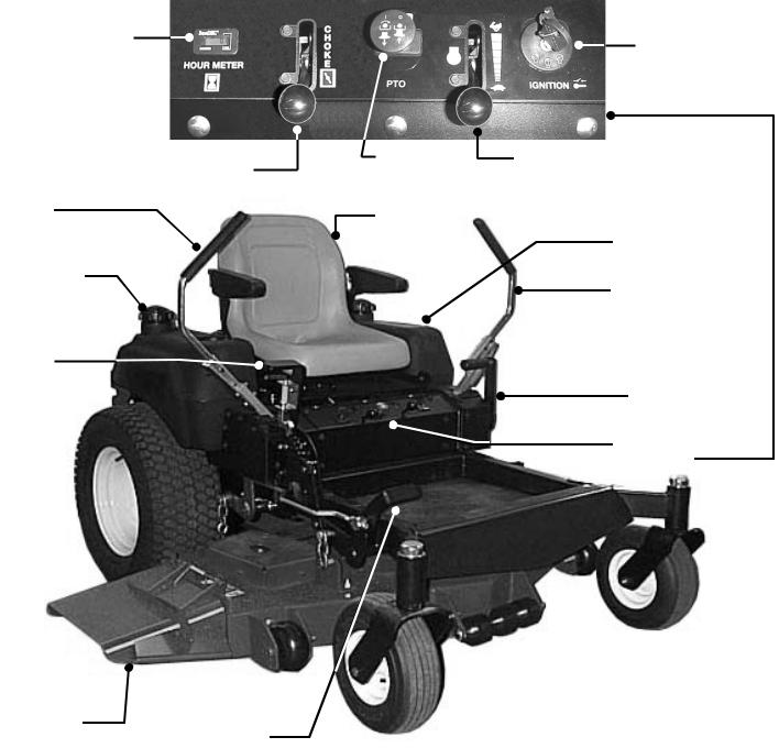
Section 1 - FAMILIARIZATION
HOUR
METER KEY SWITCH
CHOKE |
BLADE |
ENGINE SPEED |
CONTROL |
SWITCH |
CONTROL |
MOTION CONTROL |
|
|
LEVER |
OPERATOR’S |
|
|
|
|
|
SEAT |
|
|
LEFT HAND |
RIGHT HAND |
FUEL TANK |
FUEL TANK |
|
|
MOTION CONTROL |
|
LEVER |
DECK LIFT |
|
LEVER |
|
|
PARKING |
|
BRAKE LEVER |
|
CONTROL PANEL |
|
(SEE INSET) |
DISCHARGE
DEFLECTOR
DECK LIFT PEDAL
|
IMPORTANT |
|
The figures and illustrations in this manual |
|
are provided for reference only and may |
|
differ from your specific model. Contact |
FIGURE 1.1 |
your Snapper dealer if you have questions |
|
1.1 INTRODUCTION
This manual has been prepared for the operator’s of the SNAPPER MID MOUNT Z-RIDER. Its purpose, aside from recommending standard operating procedures and routine service requirements, is to promote SAFETY through the use of accepted operating practices. Read, Understand and Follow the IMPORTANT SAFETY INSTRUCTIONS on Pages 2 thru 4 of this manual and All SAFETY messages on the MID MOUNT Z-RIDER and its attachments before operating. SNAPPER recommends returning the MID MOUNT Z-RIDER to an authorized SNAPPER dealer annually for inspection and addition of any new devices which might upgrade the safety of the mower.
1.2 NOMENCLATURE
The nomenclature information above, Figure 1.1, shows the essential parts of the SNAPPER MID MOUNT Z-RIDER. It is recommended that all operators of this equipment become thoroughly familiar with the controls, components, and operation of this machine before operating. Specific details involving the engine are found in the separate engine owner’s manual. Study these manuals before operating and keep both handy for future reference. For the nearest SNAPPER dealer in your area, check the yellow pages under the heading LAWN MOWERS. For engine parts and service, look for the engine manufacturer’s dealers under the heading, ENGINES - gasoline.
6

Section 2 – SAFETY MESSAGES AND SYMBOLS
DANGER ! ROTATING PARTS
KEEP AWAY FROM MOVING PARTS
MOTION CONTROL LEVER OPERATION
PARKING BRAKE LEVER OPERATION
WEAR HEARING PROTECTION
WARNING ! AVOID SERIOUS INJURY OR DEATH
STARTING, OPERATION & STOPPING OF MACHINE
7
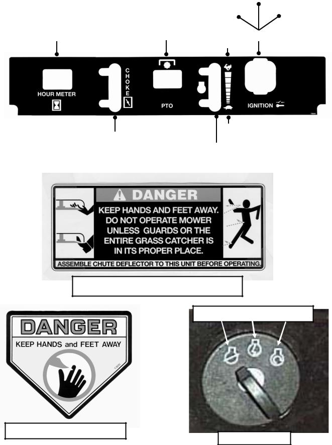
Section 2 – SAFETY MESSAGES AND SYMBOLS
|
|
RUN |
|
OFF/STOP |
START |
|
PULL SWITCH “UP” TO |
|
|
ENGAGE BLADES |
|
HOUR METER |
PUSH SWITCH “DOWN” TO |
KEYSWITCH |
DISENGAGE BLADES |
||
|
FAST |
|
CONTROL PANEL IDENTIFICATION |
|
SLOW |
|
CHOKE |
|
|
|
|
|
CONTROL |
ENGINE |
|
|
|
|
|
SPEED |
|
|
CONTROL |
DANGER! ROTATING BLADES
KEEP CHILDREN AND OTHERS OUT OF MOWING AREA
STOP RUN START
DANGER! ROTATING BLADES
IGNITION SWITCH
8
Section 3 - OPERATING INSTRUCTIONS
3.1PRE-START CHECK LIST
Make the following checks and perform the service required before each start-up.
3.1.1.Check tires and add or release air as needed to bring pressure to 12 psi in drive tires. Pressure in front caster wheels should be 25 psi.
3.1.2.Check guards, deflectors and covers to make sure all are in place and securely tightened.
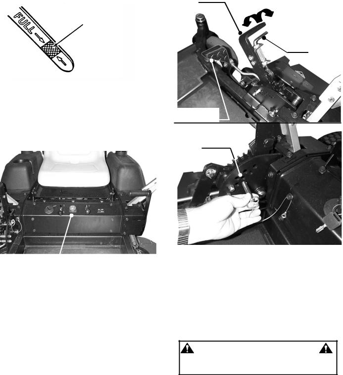
3.1.3.Check engine oil and add oil as needed to bring level up to the FULL mark. Refer to engine owner’s manual for oil specifications. See Figure 3.1.
SAFE LEVEL
AREA
FIGURE 3.1
3.1.4. Check Blade Switch to insure it works freely.
1.Pull the Blade Switch up to the “ON” position to engage or turn “ON” the mower blades.
2.Push Blade Switch down to the “OFF” position to disengage or turn “OFF” the blades.
 BLADE SWITCH
FIGURE 3.2
3.1.5.Clean exterior surfaces of cutting deck, engine and pumps of any accumulation of dirt, grass, oil, etc. Keep engine and pump air intake screens and cooling fins clear at all times.
3.1.6.Add fuel to both tanks of the machine outside where fumes can safely dissipate. Make sure both fuel filler caps are tight. Note the fuel tank selector valve. Refer to engine owner’s manual for fuel specifications.
3.1.7.Adjust position of operator’s seat. The seat is mounted on slides. Locate latch lever beneath the seat. Move lever towards the left and slide seat to the desired position. Release latch. If equipped, adjust seat suspension for operator weight.
3.1.8. Place mower in desired cutting height setting. Grasp deck lift lever and depress release latch located underneath the lever. Move lever to desired cutting height setting and release latch. Insert stop pin to desired cutting height.
IMPORTANT: There is a foot assist pedal located to the right front side of the footrest. Always use this assist pedal to raise or lower the deck to the desired cutting height. See Figure 3.3.
DECK LIFT
LEVER
RELEASE
LATCH
FOOT
ASSIST PEDAL
INSERT STOP PIN
INTO HOLES FOR
DESIRED CUTTING
HEIGHT
FIGURE 3.3
IMPORTANT: This machine is equipped with hydrostatic drive. The direction of motion and the speed of motion are controlled by the left and right motion control levers. A small movement of these controls can cause the machine to move instantly. DO NOT attempt to operate the machine until you read this manual and become familiar with its operation. Practice with the blades “OFF” disengaged, engine speed at a slow setting and in an open area away from obstacles.
WARNING
DO NOT allow operation of the machine by untrained personnel.
9

Section 3 - OPERATING INSTRUCTIONS
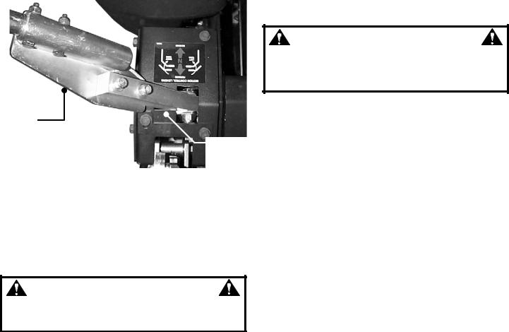
ROLL RELEASE: To roll the machine without the engine running, pressure within the hydraulic pumps must be released. There is a hydraulic pressure relief valve on the upper side of each pump that is used to release the pressure. Use a wrench to rotate both relief valves counter clockwise two full turns to open. After rolling machine, both relief valves must be rotated clockwise to close valves and tighten securely before operating machine. Machine will not move if relief valves are open. See Figure 3.4.
ROTATE RELIEF VALVE
COUNTERCLOCKWISE
TO RELIEVE PRESSURE
RELIEF VALVE
WARNING
DO NOT disengage the hydro transmission and coast down slopes. DO NOT use Roll Release Control to disengage the hydro transmission unless machine motion can be controlled and engine is off.
3.2 STARTING & STOPPING – ENGINE, BLADES, PARKING BRAKE
This machine is equipped with dual hydrostatic wheel drive transmissions. Each hydro pump is controlled by a separate motion control lever. The left lever controls the left wheel drive hydro pump and the right lever controls the right wheel drive hydro pump. These levers control the direction of motion, Forward & Reverse, and the speed of motion. Move both levers forward to propel the machine forward. Move both levers rearward to propel the machine in reverse. The speed of motion is continuously variable from neutral (zero) to the maximum. Moving the levers farther from the neutral position will cause the speed of motion to increase. To turn, move the lever on the side to which you want to turn slightly rearward of the other lever. Move levers slowly and carefully. DO NOT make sudden changes in speed or direction. Always slow machine motion before turning. To stop the motion of the machine, bring both motion control levers to the neutral position. Engage parking brake.
3.2.1. STARTING ENGINE
When the ignition key is turned the engine will not start or turn over unless, the blade switch is pushed in to the “OFF” position and the motion control levers are in the neutral lock position. Always engage parking brake before starting engine.
1.Complete pre-start checklist.
2.Sit in operator’s seat.
3.Push blade switch in to “OFF”, blades disengaged position and engage parking brake. See Figure 3.2.
4.Move choke control forward to choke position to start a cold engine. See Figure 3.5.
5.Move engine speed control to the Rabbit “FAST” position. See Figure 3.5.
6.Turn key to the start position until engine starts. See Figure 3.6.
CHOKE |
ENGINE |
KEY |
SPEED |
||
CONTROL |
CONTROL |
SWITCH |
MOTION CONTROL LEVERS
SHOWN IN THE NEUTRAL
LOCK POSITION
SHOWN FROM OPERATOR’S VIEW POINT
FIGURE 3.5
10
Section 3 - OPERATING INSTRUCTIONS
3.2.1. STARTING ENGINE
NOTE: If after 5 seconds of cranking the engine does not start, release the key. Attempt starting again after waiting for approximately 20 seconds.
7. After engine starts, move the choke control to the “OFF” or no choke position. Allow a brief warm-up until engine runs smooth.
3.2.2. STOPPING ENGINE
1. Stop engine by turning key to “STOP” position. Move engine speed to the Turtle “SLOW” position and turn key to “STOP”. See Figure 3.6.
KEYSWITCH
SHOWN FROM OPERATOR’S VIEW POINT
FIGURE 3.6
WARNING
DO NOT operate blades in reverse. STOP blades. LOOK and SEE behind and down for children, pets, and hazards before and while backing.
3.2.3.STARTING MOWER BLADES
1.Start engine and set engine speed control to the Rabbit “FAST” position. See Figure 3.5.
2.Pull the Blade Switch up to the “ON” position to
engage or turn “ON” the mower blades. See Figure 3.2.
3.2.4.STOPPING MOWER BLADES
1.Push Blade Switch down to “OFF” position to disengage or turn “OFF” the blades.
2.Move engine speed control to the Turtle “SLOW” position. Turn key to “STOP” position.
WARNING
Once blades are disengaged, they should come to a complete stop in 7 seconds. If the blades continue to rotate after 7 seconds, the electric clutch should be checked. Adjustment or replacement of electric clutch may be necessary. Return the machine to an authorized Snapper dealer for replacement. DO NOT CONTINUE to operate mower if blades fail to stop in 7 seconds.
3.2.5. PARKING BRAKE
1.Engage parking brake by pulling the parking brake lever back to the engaged position. See Figure 3.7.
NOTE: Engaging parking brake prior to placing motion control levers in the neutral lock position will cause engine to die. See Figure. 3.7.
2.Release parking brake by pushing parking brake lever forward to the released position. See Figure 3.8.
PARKING BRAKE LEVER IN ENGAGED “ON” POSITION
MOTION
CONTROL
LEVER
LEVER SHOWN IN
THE NEUTRAL
LOCK POSITION
FIGURE 3.7
PARKING BRAKE LEVER IN RELEASED “OFF” POSITION
FIGURE 3.8
WARNING
DO NOT park the machine on slopes. DO NOT leave machine with engine running. Stop engine. Stop blades. Engage parking brake. Remove key.
11
Section 3 - OPERATING INSTRUCTIONS
3.3CUTTING HEIGHT ADJUSTMENT
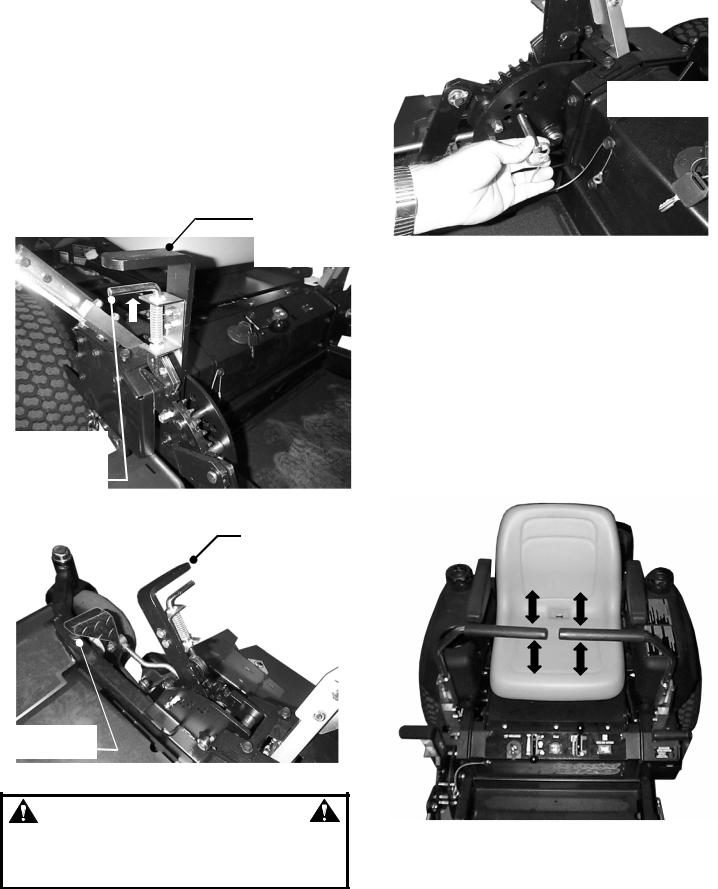
1.Adjust cutting height, as desired, to any position, using deck lift lever. The release latch should be pulled up when lowering the deck. When raising the deck, the release latch does not have to be pulled up. IMPORTANT: There is a foot assist pedal located to the right front side of the footrest. Always use this assist pedal to raise or lower the deck to the desired cutting height. See Figure 3.9 & 3.10.
2.If a specific deck height is desired each time the machine is used, insert the stop pin to desired cutting height. See Figure 3.11.
NOTE: The engine does not have to be running to adjust cutting height.
DECK LIFT
LEVER SHOWN IN
HIGH CUTTING
HEIGHT
PULL RELEASE
LATCH UP WHEN
CHANGING THE
DECK HEIGHT
FIGURE 3.9
DECK LIFT LEVER
SHOWN IN LOW
CUTTING HEIGHT
POSITION
DECK LIFT
ASSIST PEDAL
FIGURE 3.10
WARNING
DO NOT make turns at high speed. Slow machine motion. Move motion control lever gently and with caution. DO NOT make sudden changes in speed or direction.
 6 HOLE POSITIONS
FOR STOP PIN
FIGURE 3.11
3.4OPERATIONMOTION CONTROLS
3.4.1.DRIVING MACHINE
1.Start engine. Release parking brake.
2.Move motion control levers gently and with caution in desired direction. See Figure 3.12. FORWARD - Move both control levers forward. REVERSE - Move both control levers rearward. LEFT TURN - Move left control rearward or move right control lever forward.
RIGHT TURN - Move left control forward or move right control lever rearward.
ZERO RADIUS TURN - Move one control lever forward and move the other control lever rearward simultaneously.
REARWARD
MOVEMENT
FORWARD
MOVEMENT
FIGURE 3.12
12
Section 3 - OPERATING INSTRUCTIONS
3.4.2. STOPPING MACHINE
1. Return motion control lever to the neutral position & the neutral lock position.
IMPORTANT: Operator must use hand assistance to bring both motion control levers to the neutral position & the neutral lock position.
MOTION
CONTROL
LEVER
NEUTRAL
LOCK
POSITION
FIGURE 3.13
2.Engage parking brake.
3.Push Blade Switch down to the “OFF” position to disengage or turn “OFF” the blades.
4.Stop engine. Move engine speed control to turtle “SLOW” position. Turn key to stop position.
5.Remove key.
WARNING
DO NOT park the machine on slopes. DO NOT leave machine with engine running. Stop engine. Stop blades. Engage parking brake. Remove key.
3.5 SAFETY INTERLOCK SYSTEM CHECKS
This machine is equipped with an electrical safety interlock system that is provided for the safety of the operator and others. All safety devices must be in place and functioning properly before operating the machine. Perform the following interlock system checks periodically during the operating season. Contact your authorized Snapper dealer if you have questions.
WARNING
DO NOT operate machine if any safety interlock or safety device is not in place and functioning properly. DO NOT attempt to defeat, modify or remove any safety device.
ENGINE MUST NOT START IF:
1.Motion Control Lever(s) are not in the neutral lock position OR,
2.Parking Brake disengaged and Operator not seated in the Operator’s Seat OR,
3.Blade Switch in the “ON” blades engaged position.
ENGINE SHOULD START IF:
1.Blade Switch in the “OFF” blades disengaged position AND,
2.Motion Control Levers are both in the neutral lock position AND,
3.Operator properly seated in the Operator’s Seat OR,
4.Parking Brake engaged.
NOTE: The engine can be started with the parking brake disengaged only if conditions in 1, 2 and 3 have been met.
ENGINE MUST BEGIN TO STOP IF:
1.Motion Control Levers are moved from the neutral lock position with Parking Brake engaged OR,
2.Operator rises off of seat with Blade Switch in “ON” blades engaged position OR,
3.Operator rises off of seat with Parking Brake disengaged.
IMPORTANT: Engine and blades will continue to run if Operator becomes reseated prior to engine coming to a complete stop. After coming to a complete stop, the blade switch must be moved to the “OFF” position before engine can be restarted. Engine and blades must come to a complete stop within 7 seconds after the operator rises off the seat or the blade switch is moved to the “OFF” position.
13
 Loading...