


LT150H33IBV

Safety Instructions & Operator’s Manual for
LAWN TRACTOR
HYDROSTATIC DRIVE
SERIES I
MODELS
LT150H33IBV
LT150H38IBV
WLT150H38IBV
WLT170H38IBV
MODEL NUMBER EXPLANATION
LT 150 H 38 I B V
MODEL DESIGNATION
ENGINE HP ENGINE TYPE
DRIVE SYSTEM TYPE ENGINE MODEL
CUTTING WIDTH SERIES DESIGNATION
LT – Lawn Tractor Model Designation 33 – 33” Cutting Width Mower
WLT – Lawn Tractor Model Designation 38 – 38” Cutting Width Mower
150 – 15.0 HP Engine Horse Power I – Series Designation
170 – 17.0 HP Engine Horse Power B – Briggs & Stratton
H – Hydrostatic Transmission V – Over Head Valve Type Engine
Thank you for buying a SNAPPER product! Before operating the Lawn Tractor, read and follow the
“IMPORTANT SAFETY INSTRUCTIONS” on pages 2 & 3, all other instructions contained in this manual and the
accompanying booklet “About Power Mower Safety”. Lawn mowers and all power equipment can be potentially
dangerous if used improperly. REMEMBER: SAFETY REQUIRES CAREFULL USE IN ACCORDANCE WITH
INSTRUCTIONS AND COMMON SENSE!
COPYRIGHT © 2002
SNAPPER INC.
ALL RIGHTS RESERVED
MANUAL No. 7-2343 (I.R. 6/28/02)

IMPORTANT SAFETY INSTRUCTIONS
WARNING: This powerf ul cutting machine is capab le of amputating hand s and feet and can throw objects that
can cause injury and damage! Failure to comply with the follow ing SAFETY instru ctions could resu lt in serious
injury or death to the operator or other persons. The owner of the machine must understand these instructions
and must allow only persons who understand these instructions to operate machine. Each person operating the
machine must be of sound mind and body and must not be under the influence of any substance, which might
impair vision, dexterity or judgment. If you have any questions pertaining to your machine which your dealer
cannot answer to your satisfaction, call or write the Customer Service Department at SNAPPER, McDonough,
Georgia 30253. Phone: (1-800-935-2967).
PROTECTION FOR CHILDREN
Tragic accidents can occu r if the operator is not alert
to the presence of children. Children are often
attracted to the machine and the mowing activity.
Never assume that children will remain where you last
saw them.
1. KEEP children out of the mowing area and under
the watchful care of a responsible adult.
2. DO NOT allow children in yard when machine is
operated (even with the blade OFF).
3. DO NOT allow children or others to ride on
machine or on attachments (even with the blades
OFF). They may fall and be seriously injured.
4. DO NOT allow pre-teenage children to operate
machine.
5. ALLOW only responsible adults & teenagers with
mature judgment under close adult supervision to
operate machine.
6. DO NOT operate blades in reverse. STO P BLADES.
LOOK and SEE behind an d down for children, pets
and hazards before and while backing.
7. USE EXTRA CARE when approaching blind
corners, shrubs, trees, or other objects that may
obscure vision.
PROTECTION AGAINST TIPOVERS
Slopes are a major factor related to loss-of-control
and tip-over accidents, which can result in severe
injury or death. All slopes require extra CAUTION. If
you cannot back up the slope or if you feel uneasy on
the slope, DO NOT mow it. Use extra care with grass
catchers or other attachments; these affect the
handling and the stability of the machine.
1. DO NOT operate machine on slopes exceeding 15
degrees (27% grade).
2. Exercise EXTREME CAUTION on slop es above 10
degrees (18% grade). Turn blades OFF when
traveling uphill. Use a slow speed and avoid
sudden or sharp turns.
3. DO NOT operate machine back and forth across
face of slopes. Operate up and down. Practice on
slopes with blades off.
4. AVOID uphill starts. If machine stops going uphill
or tires lose traction, turn blades OFF and back
slowly down the slope.
PROTECTION AGAINST TIPOVERS
(Continued From Previous Column)
5. STAY ALERT for holes and other hidden hazards.
Tall grass can hide obstacles. Keep away from
ditches, washouts, culverts, fences and
protruding objects.
6. KEEP A SAFE DISTANCE (at least 3 feet) away
from edge of ditches and other drop offs. The
machine could turn over if an edge caves in.
7. Always begin forward motion slowly and with
caution.
8. Use weights or a weighted load carrier in accordance
with instructions su pplied with a grass catcher. DO
NOT operate machine on slopes exceeding 10
degrees (18% grade) when equipped with grass
catcher.
9. DO NOT put your foot on the ground to try to
stabilize the machine.
10. DO NOT operate machine on wet grass. Reduced
traction could cause sliding.
11. DO NOT operate machine under any condition
where traction, steering or stability is doubtful.
PREPARATION
1. Read, understand, and follow instructions and
warnings in this manual and on the machine,
engine and attachments. Know the controls and
the proper use of the machine before starting.
2. Only mature, responsible persons shall operate
the machine and only after proper instruction.
3. Data indicates that operators age 60 and above,
are involved in a large percentage of mowerrelated injuries. These operators should evaluate
their ability to operate the mower safely enough to
protect themselves and others from serious injury.
4. Handle fuel with extra care. Fuels are flammable
and vapors are explosive. Use only an approved
fuel container. DO NOT remove fuel cap or add
fuel with engine running. Add fuel outdoors only
with engine stopped and cool. Clean spilled fuel
from machine. DO NOT smoke.
5. Practice operation of machine with BLADES OFF
to learn controls and develop skills.
6. Check the area to be mowed and remove all
objects such as toys, wire, rocks, limb s and other
objects that could cau se injury if thrown by blade
or interfere with mowing.
2

IMPORTANT SAFETY INSTRUCTIONS
PREPARATION
(Continued From Previous Page)
7. Keep people and pets out of mowing area.
Immediately STOP blades, STOP engine, and
STOP machine if anyone enters the area.
8. Check shields, deflectors, switches, blade
controls and other safety dev ices frequently for
proper operation and location.
9. Make sure all safety decals are clearly legible.
Replace if damaged.
10. Protect yourself w hen mowing and wear safety
glasses, long pants and substantial footwear.
11. Know how to STOP blades and engine quickly
in preparation for emergencies.
12. Use extra care when loading or unloading the
machine into a trailer or truck.
13. Check grass catcher components frequently for
signs of wear or deterioration and replace as
needed to prevent injury from thrown objects
going through weak or worn spots.
OPERATION
1. Mount and dismount machine from left side.
2. Start engine from operator's seat, if possible.
Make sure blades are OFF and parking brake is
set.
3. DO NOT leave machine with engine running.
STOP engine, STOP blades, SET brake, and
Remove key before leaving operators position
of any reason.
4. DO NOT operate machine unless properly
seated with feet on feet rests or pedal(s).
5. STOP BLADES and ENGINE and make sure
blades have stopped before removing grass
catcher or unclogging mower to prevent loss of
fingers or hand.
6. Blades must be OFF except when cutting grass.
Set blades in highest position when mowing
over rough ground.
7. Keep hands an d feet away from rotating blades
underneath deck. DO NOT place foot on ground
while BLADES are ON or machine is in motion.
8. DO NOT operate machine without entire grass
catcher or guards in place. DO NOT point
discharge at people, passing cars, windows or
doors.
9. Slow down before turning.
10. Watch out for traffic when near or crossing
roadways.
11. STOP engine immediately after striking an
obstruction. Inspect machine and repair
damage before resuming operation.
12. Operate machine only in daylight or with good
artificial light.
13. Move joystick (if equipped) SLOWLY to
maintain control during speed and directional
changes.
OPERATION
(Continued From Previous Column)
14. Exercise CAUTION when pullin g loads. Limit loads
to those you can safely control and attach loads to
hitch plate as specified w ith SNAPPER attachment
instructions.
15. DO NOT operate engine in enclosed areas. Engine
exhaust gases contain carbon monoxide, a deadly
poison.
MAINTENANCE
1. DO NOT store machine or fuel container inside
where fumes may reach an open flame, spark or
pilot light such as in a water heater, furnace,
clothes dryer or other gas appliance. Allow
engine to cool before storing machine in an
enclosure. Store fuel container o ut of the reach
of children in a well ventilated, unoccupied
building.
2. Keep engine free of grass, leaves or excess
grease to reduce fire hazard and engine
overheating.
3. When draining fuel tank, drain fuel into an
approved container outdoors and away from
open flame.
4. Check brakes frequently; adjust, repair or
replace as needed.
5. Keep all bolts, nuts and screws properly tight.
Check that all cotter pins are in proper position.
6. Always provide adequate ventilation when
running engine. Exhaust gases contain carbon
monoxide, an odorless and deadly poison.
7. Disconnect negative (black) cable from battery
before performing maintenance or service.
Cranking engine could cause injury.
8. DO NOT work under machine without safety
blocks.
9. Service engine and make adjustments only
when engine is stopped. Remove spark plug
wire(s) from spark plug(s) and secure wire(s)
away from spark plug(s).
10. DO NOT change engine governor speed
settings or overspeed engine.
11. Lubricate machine at intervals specified in
manual to prevent controls from binding.
12. Mow er blades are sharp and can cut. Wrap the
blades or wear heavy leather gloves and use
CAUTION when handling them.
13. DO NOT test for spark by grounding spark plug
next to spark plug hole; spark plug could ignite
gas exiting engine.
14. Have machine serviced by an authorized
SNAPPER dealer at least once a year and have
the dealer install any new safety devices.
15. Use only genuine SNAPPER replacement parts to
assure that original standards are maintained.
16. If battery is removed, DO NOT operate engine
without insulating Positive + battery cable
terminal with electrical tape or sparking from
the battery cables can result.
3

TABLE OF CONTENTS
IMPORTANT SAFETY INSTRUCTIONS..........2 - 3
TABLE OF CONTENTS........................................4
SECTION 1 - FAMILIARIZATION.........................5
Components ........................................................5
Controls................................................................5
SECTION 2 -
OPERATING INSTRUCTIONS ........................6-11
Pre-start Checklist ..............................................6
Operator’s Seat Adjustment ..............................6
Starting & Stopping Engine................................7
Starting & Stopping Wheel Drive .......................8
Starting & Stopping Mower Blades................ 8-9
Parking Brake.......................................................9
Cutting Height Adjustment.................................9
Rolling Tractor With Engine Off .......................10
Reverse Lockout Mechanism ...........................11
SECTION 3 -
MAINTENANCE INSTRUCT IONS .................12-16
Service - After First 5 Hours........................12
Change Engine Oil..........................................12
Check Blade Brake.........................................12
Check Mower Blade.................................. 12-13
Check Deck Drive Belt ...................................13
Service – Every 25 Operating Hours.........13
Mower Components.......................................13
Check Blade Brake.........................................13
Lubrication (Tractor)................................ 14-15
Front Wheel Bearings ....................................14
Axle Spindles ..................................................14
Clutch/Brake Pivot..........................................14
Steering Sector Gear......................................14
Steering Shaft .................................................14
Steering Drag Link..........................................14
Steering Tie Rod.............................................15
Blade Engagement Mechanism.....................15
Park Brake Lever ............................................15
Deck Lift Mechanism......................................15
Service - Annually.....................................15-16
Engine .............................................................15
Fuel Filter................................................... 15-16
Spark Plug.......................................................16
Hydrostatic Transmission Oil........................16
The figures and illustrations in this manual are
provided for reference only and may differ from your
specific model. Contact your Snapper dealer if you
have questions.
IMPORTANT
SECTION 4 -
ADJUSTMENTS & REPAIR...........................17-32
Engine Adjustments & Repair..........................17
Mower Deck & Component Adjustments........17
Blade Brake Adjustment...................................17
33” Deck Blade Brake Adjustment ...............17
38” Deck Blade Brake Adjustment ...............17
Blade Belt Adjustment (33” Deck) ...................18
Blade Belt Adjustment (38” deck)....................18
Adjusting Mower Blade (33” Deck).............18-19
33” Side To Side ...........................................18-19
(Deck Level Adjustment)
33” Front To Rear Sector Plates ......................20
(Deck Level Adjustment)
33” Front To Rear Front Lift Rod .....................20
(Deck Level Adjustment)
38” Side To Side ................................................21
(Deck Level Adjustment)
38” Front To Rear..............................................22
(Deck Level Adjustment)
Brake Adjustment - HYDRO DRIVE..................22
Steering Adjustment .........................................23
Shifter Adjustment ............................................23
Traction Drive Belt Adjustment........................24
Mower Blade Service ...................................25-26
Blade Wear Limits..........................................25
Mower Blade Sharpening ..............................25
Mower Blade Replacement.......................25-26
Traction Drive Belt Removal/Replace.........26-28
Blade Belt Removal & Replacement................29
33” Deck Drive Belt........................................29
38” Deck Drive Belt........................................29
Battery Service .............................................30-31
AVAILABLE ACCESSORIES..................................32
SECTION 5 -
ELECTRICAL SYSTEM...................................... 33
Schematic - Briggs & Stratton..........................33
TROUBLESHOOTING GUIDE ...................... 34-35
MAINTENANCE SCHEDULE ............................. 36
MAINTENANCE PARTS..................................... 36
WARRANTY .................................................... 37
PRIMARY MAINTENANCE............................38-41
PRODUCT REGISTRATION FORM................... 42
4
Section 1 - FAMILIARIZATION
(UNDER HOOD)
CONTROL PANEL
PEDAL
DOWN
CLUTCH/BRAKE
CUTTING HEIGHT
ADJUSTMENT LEVER
SEAT
ADJUSTMENT
KNOB
SPEED
CONTROL
LEVER
BATTERY
(UNDER SEAT)
OVERRIDE
LEVER
BLADE
ENGAGEMENT
LEVER
DISCHARGE
DEFLECTOR
MOWING DECK
(33” SHOWN)
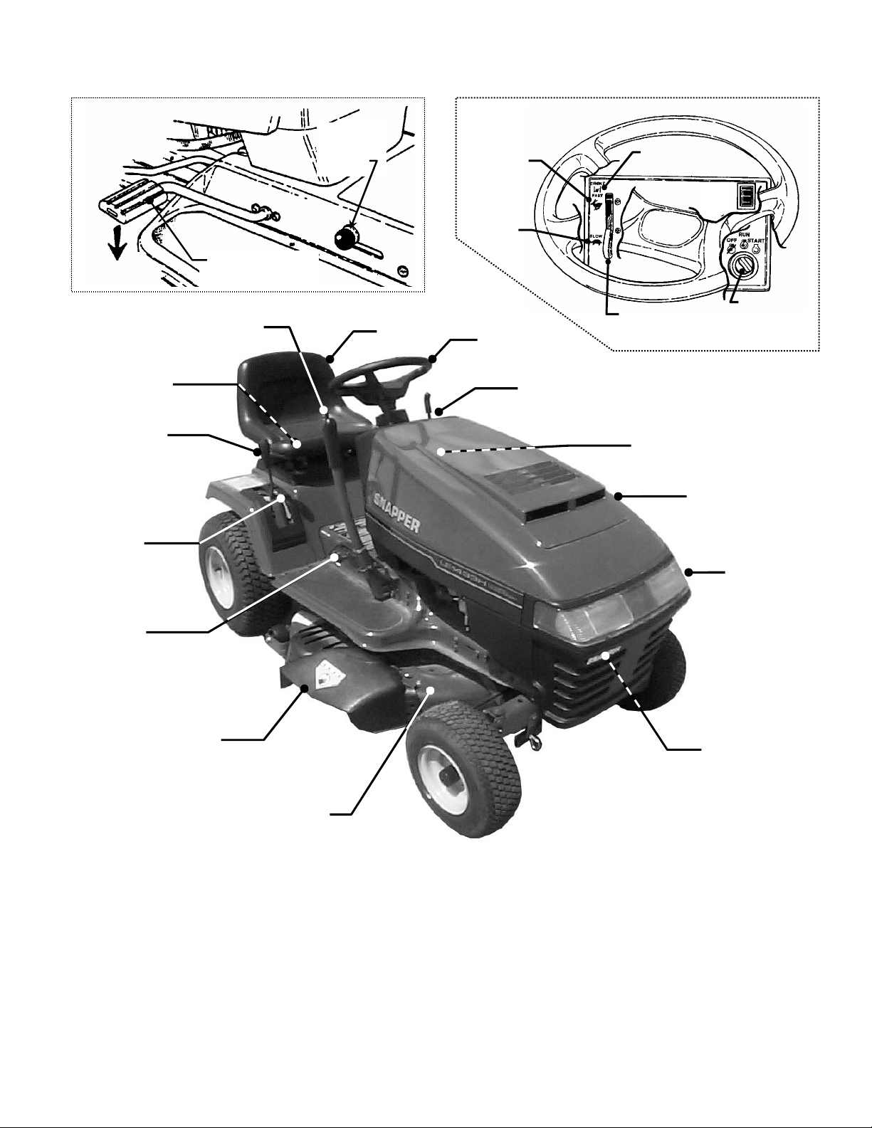
COMPONENTS
The nomenclature drawings above, illustrate the
essential components of the SNAPPER Lawn Tractor. It
is recommended that all operators of this equipment
become thoroughly familiar with the components and
their operation BEFORE OPERATING.
Specific details involving the engine are found in the
separate Engine Owner’s Manual.
PARK
BRAKE
LEVER
OPERATOR’S
SEAT
FIGURE 1.1
FAST
SLOW
STEERING
WHEEL
DASHBOARD
CONTROLS
CHOKE
KEY
ENGINE SPEED
CONTROL
FUEL TANK
HOOD
HEADLIGHTS
ENGINE
Study the Important Safety Instructions, this Operator’s
Manual and Engine Owner’s Manual before operating
this machine. Keep these manuals available for future
reference.
CONTROLS
All operators should be acquainted with the operator’s
controls before attempting start-up or operation of the
Lawn Tractor. See the Control Panel drawing above.
6
Section 2 - OPERATING INSTRUCTIONS
2.1 PRE-START CHECKLIST
Make the following checks and perform service as
required before each start-up.
2.1.1. Check tires and add air as needed to bring
pressure to 12 P.S.I. in front tires and 12 P.S.I. in
rear tires.
2.1.2. Check guards, deflector s and covers to make
sure all are in place and securely tightened. I f guards
are missing or damaged, replace BEFORE using
mower.
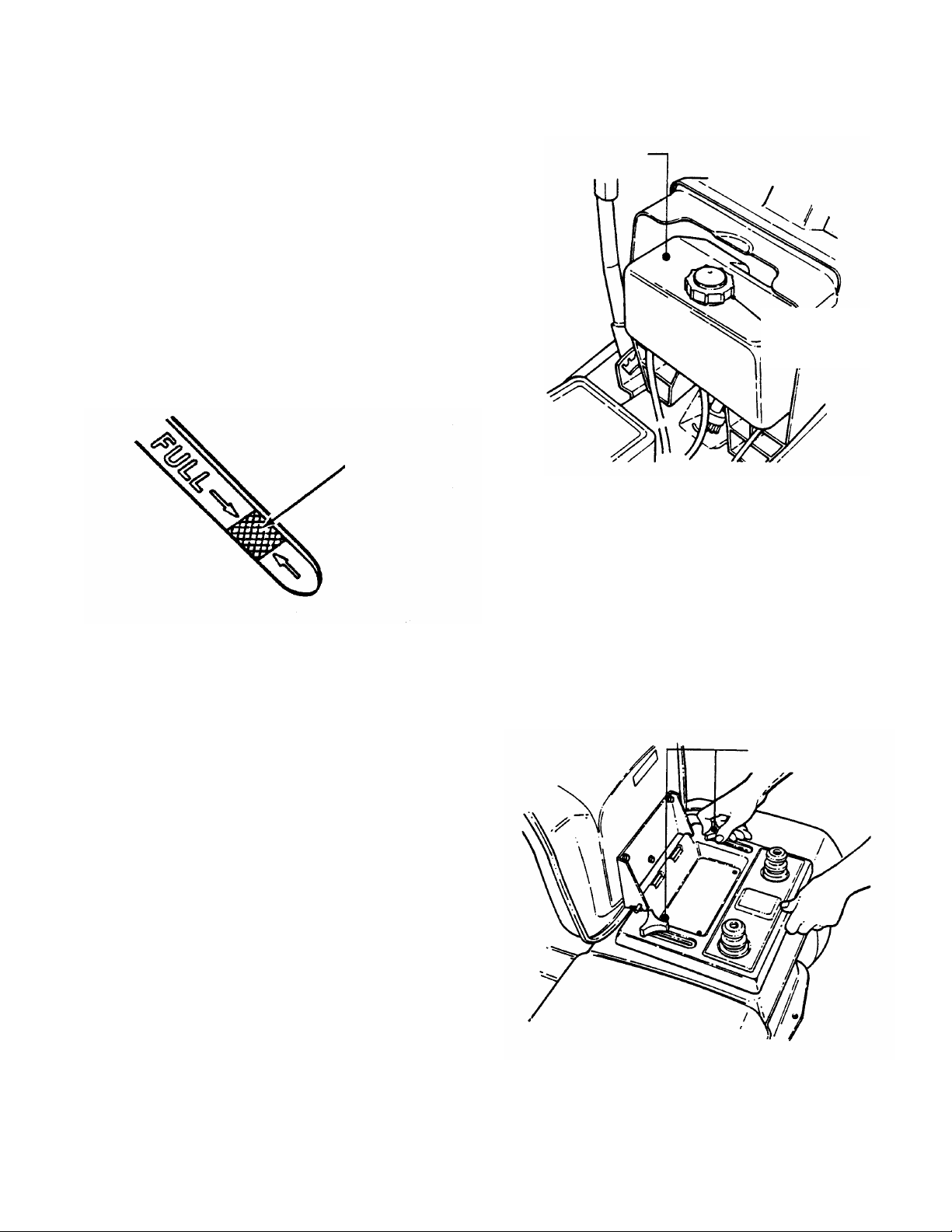
2.1.3. Check engine oil and add oil as needed to
bring level up to, but not over, the FULL mark . Ref er to
engine owner’s manual for oil specifications. See Figure
2.1.
SAFE
LEVEL
AREA
FIGURE 2.1
2.1.4. Check blade engagement lever to insure it
operates properly. The blade engagement lever
must be moved manually from “ON” to “OFF” to
stop blade.
2.1.5. Clean exterior surf aces of cutting deck , engine
and tractor of any accumulation of dirt, grass, oil, etc.
Keep engine air intake screens and cooling fins clean at
all times.
2.1.6. With engine “OFF” move the tractor outside
and add fuel to the fuel tank. Securely tighten fuel cap
after refueling. Refer to engine owner’s manual for fuel
specifications. See Figure 2.2.
2.1.7. Check Reverse Lockout Mechanism. With
engine “OFF”, rai se b l ade engagem ent lever to "ON".
The speed control lever cannot be shifted into
“Reverse”.
FUEL TANK
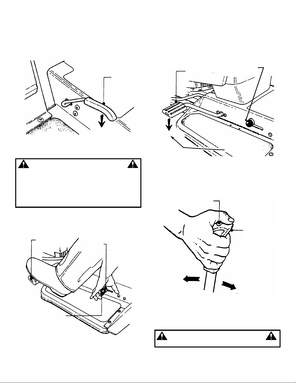
2.2 OPERATOR’S SEAT ADJUSTMENT
2.2.1. FRONT TO REAR ADJUSTMENT
1. With the engine "OFF", raise operator's seat and
loosen the two adjusting knobs on the seat support.
Lower the seat. Sit in the operator's seat and slide the
seat forward or backward until the clutch/brake pedal
can be fully depressed comfortably. Raise seat and
tighten the adjusting knobs to secure seat in position.
See Figure 2.3.
TIGHTEN CAP
AFTER
FILLING TANK
FIGURE 2.2
LOOSEN ADJUSTING
KNOBS TO ADJUST
SEAT
FIGURE 2.3
7
Section 2 - OPERATING INSTRUCTIONS
POSITION
SWITCH
2.3 STARTING & OPERATION
2.3.1. STARTING ENGINE
1. Take a comfortable position in seat of machine,
look around to make sure that the area you are going to
mow is clear of people, children and pets . Take note of
any stationary obstacles!
NOTE: The interlock system will prevent the engine from
starting if the blade engagement lever is in the "ON" (up)
position or if the c lutch/brak e pedal is not fully depressed. If
the interlock system ever f ails to work , DO NOT OPERAT E
the tractor until the interlock has been repaired.
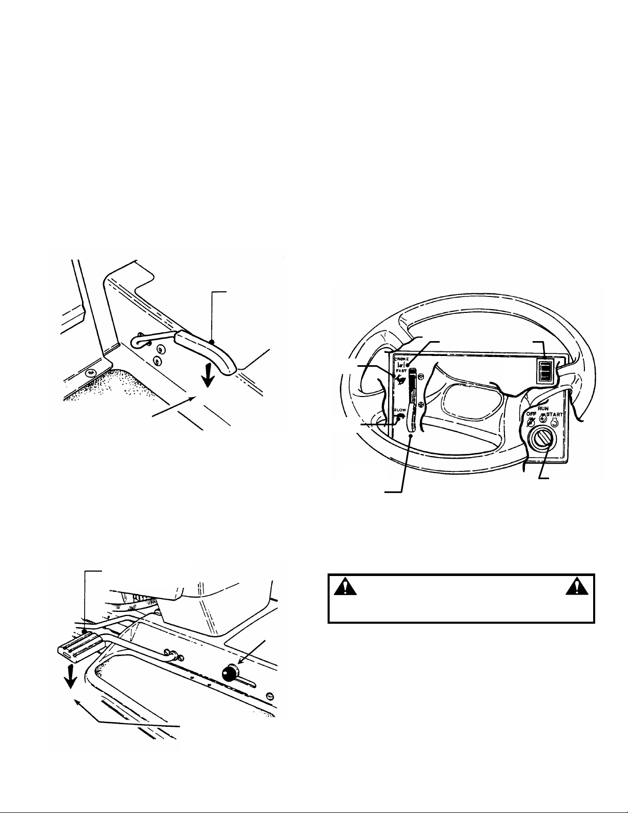
2. Push blade engagement lever down to the "OFF"
position. See Figure 2.4.
BLADE
ENGAGEMENT
LEVER
5. Choke engine for cold s tarting by moving engine
speed control to "CHOKE" position. Little or no
choking will be needed when restarting a warm
engine. Insert key in switch. Turn key to "START"
position to crank engine and hold until engine starts,
then release key to “RUN” position. See Figure 2.6.
NOTE: DO NOT crank engine for more than five
seconds at a time. T his will help prevent the starter f rom
overheating and/or running down the battery. If cranking
time is more than f ive seconds, loc ate and correct cause
of starting problem.
6. After engine starts, release key, move the
engine speed control to "FAST" position and allow
engine to warm up before proceeding. See Figure
2.6.
OFF
PUSH BLADE
ENGAGEMENT LEVER
DOWN TO “OFF” TO
START ENGINE
FIGURE 2.4
3. Depress the clutch/brake pedal fully. See Figure 2.5.
4. Move speed control lever to neutral.
NOTE: T he seat interlock will shut off the engine if the
operator gets off the seat without setting the parking
brake or if the blade is running. If the interlock ever fails
to work, DO NOT OPERATE the tractor until the
interlock has been repaired.
CLUTCH/BRAKE
PARK BRAKE
LEVER
DOWN
PUSH PEDAL ALL THE
WAY DOWN TO START
ENGINE
FIGURE 2.5
CHOKE
FAST
SLOW
ENGINE
SPEED
CONTROL
LIGHT
KEY
FIGURE 2.6
WARNING
DO NOT leave machine with engine running. Stop
engine. Stop blade. Set parking brake. Remove key.
8
Section 2 - OPERATING INSTRUCTIONS
MOWER BLADE(S)
KEY
2.3 STARTING & OPERATION (continued)
2.3.2. STARTING WHEEL DRIVE
1. Shift speed control lever to neutral.
2. Start engine. Refer to Section “STARTING
ENGINE”.
3. Release clutch/brake pedal.
4. Slowly shift speed control lever forward for
forward motion or to the rear f or revers e motion. See
Figure 2.7.
SPEED CONTROL LEVER
NEUTRAL
REVERSE
2.4 STOPPING ENGINE, BLADE, & WHEEL DRIVE
2.4.1. STOPPING ENGINE
1. Stop engine by turning key to the "OFF" position.
See Figure 2.9.
OFF
RUN
START
FORWARD
SPEEDS
FIGURE 2.7
2.3.3. STARTING MOWER BLADE
1. Start engine. Refer to Section “STARTING
ENGINE”.
2. Raise blade engagement lever to "ON". See
Figure 2.8.
PULL BLADE
ENGAGEMENT LEVER UP
TO “ON” TO START
ON
BLADE
ENGAGEMENT
LEVER
FIGURE 2.8
WARNING
DO NOT operate blades in reverse. STOP BLADES.
LOOK and SEE behind and down for children, pets
and hazards before and while backing.
FIGURE 2.9
2.4.2. STOPPING WHEEL DRIVE
1. Fully depress clutch/brake pedal to stop wheel
drive. See Figure 2.10.
CLUTCH/BRAKE
PEDAL
FULLY DEPRESS
CLUTCH/BRAKE PEDAL TO
STOP WHEEL MOTION
FIGURE 2.10
9
Section 2 - OPERATING INSTRUCTIONS
THE WAY DOWN
2.4 STOPPING
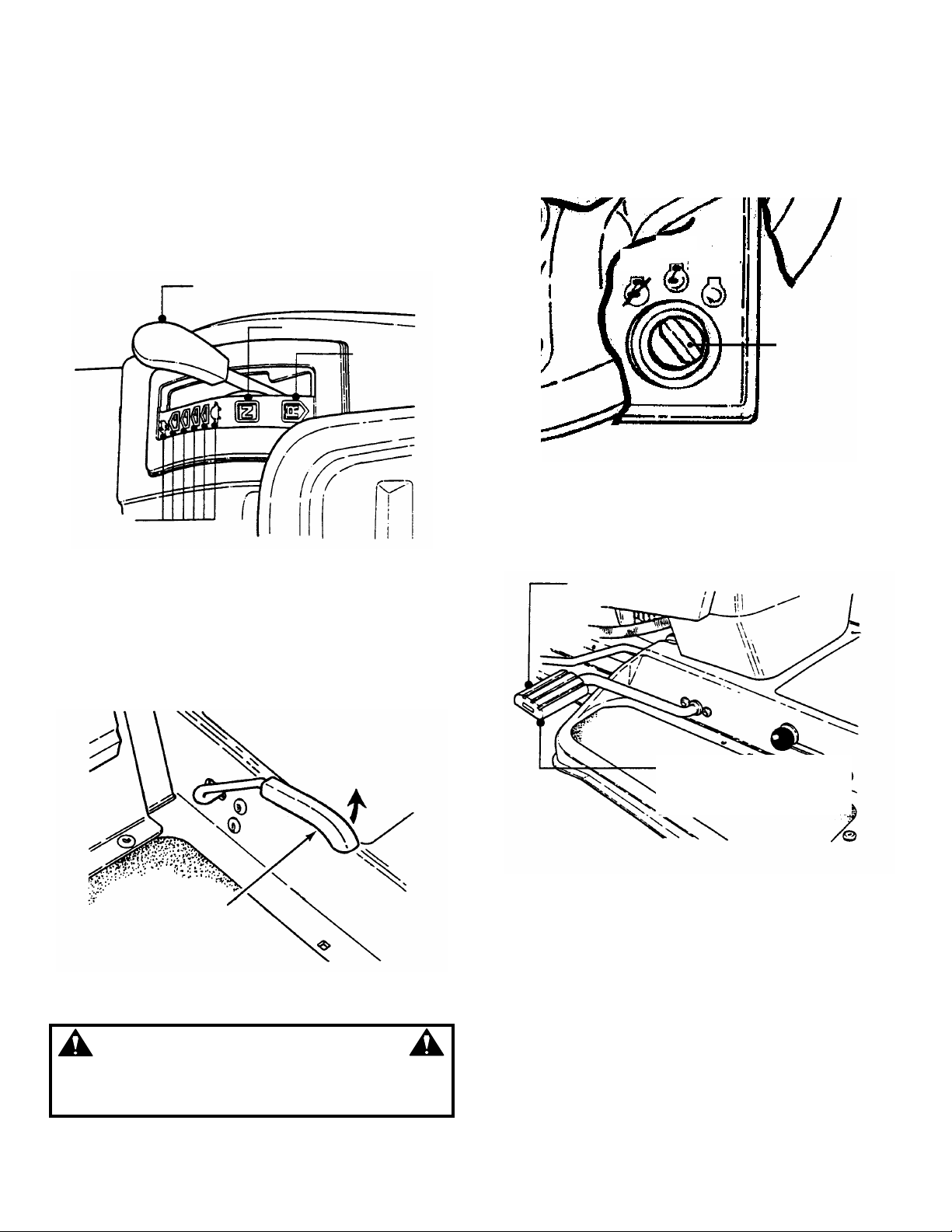
2.4.3. STOPPING MOWER BLADE
1. Stop mower blade by moving blade engagement
lever down to the "OFF" position. See Figure 2.11.
BLADE
ENGAGEMENT
LEVER
2.4.5. RELEASING PARK BRAKE
1. Fully depress clutch/brake pedal. Move park brake
lever “DOWN” to release park brake. Release
clutch/brake pedal. See Figure 2.13.
CLUTCH/BRAKE
PEDAL
PARK BRAKE
LEVER
OFF
FIGURE 2.11
WARNING
Once blade is disengaged, it should come to a
complete stop in 5 seconds or less. If the blade
continues to rotate after 5 seconds, the blade brake
must be adjusted. Refer to Section “BLADE BRAKE
ADJUSTMENT” for adjustment procedures or return
machine to dealer for adjustment. DO NO T CONTINUE
to operate mower until blade brake is properly adjusted.
2.4.4. SETTING PARK BRAKE
1. Fully depress clutch/brake pedal.
2. Move park brake lever up into slot. See Figure 2.12.
PUSH PEDAL ALL
PARK BRAKE
LEVER
FULLY DEPRESS
CLUTCH/BRAKE
PEDAL
FIGURE 2.13
2.5. CUTTING HEIGHT ADJUSTMENT
1. Depress lock button on c utting height adjustm ent
lever. See Figure 2.14.
DEPRESS
LOCK BUTTON
CUTTING
HEIGHT
ADJUSTMENT
MOVE PARK BRAKE
LEVER “UP” TO
ENGAGE PARK BRAKE
FIGURE 2.12
HIGHEST CUT
LOWEST CUT
FIGURE 2.14
2. Raise or lower deck to any of six positions as
desired. Release lock button.
WARNING
DO NOT park machine on slopes.
10
Section 2 - OPERATING INSTRUCTIONS
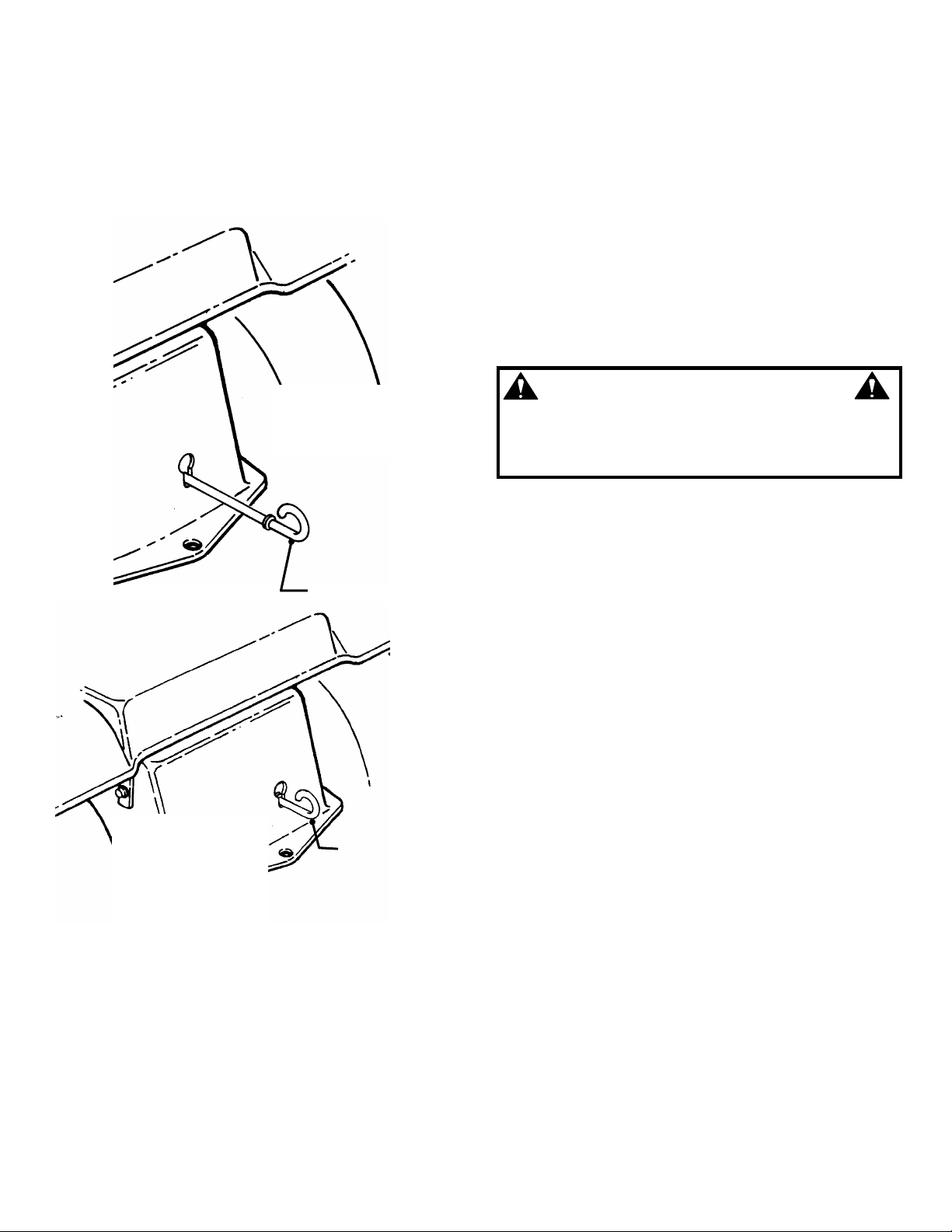
2.6. ROLLING TRACTOR WITH ENGINE OFF
2.6.1. Rolling Hydro Models
1. With engine "OFF", move to rear of tractor.
2. Pull the roll release control all the way out to
disengage the hydro transmission. See Figure 2.15.
PULL ROLL RELEASE
CONTROL ALL THE WAY
OUT TO DISENGAGE
HYDRO TRANSMISSION
PUSH ROLL RELEASE
CONTROL ALL THE WAY
IN TO ENGAGE HYDRO
TRANSMISSION
ROLL RELEASE
CONTROL
ROLL RELEASE
CONTROL
FIGURE 2.15
3. Move tractor to desired location.
4. Push roll release control all the way in to engage
hydro transmission. See Figure 2.15.
5. Set park brake.
NOTE: The transmission will not propel the tractor if it is
left in the "ROLL" position.
WARNING
DO NOT disengage the hydro transmission and coast
down slopes. DO NOT use Roll Release Control to
disengage the hydro transmission unless machine
motion can be controlled and engine is off.
11
Section 2 - OPERATING INSTRUCTIONS
2.7. REVERSE LOCKOUT MECHANISM
Data indicates that tragic back-over accidents occur
each year. These accidents usually involve unsupervised
children. Many times these children have been given
rides on the mac hine and have been trained to view this
potentially dangerous piece of machinery as fun rather
than being taught how to avoid danger.
This riding mower has a Reverse Lockout Mechanism.
This mechanis m prevents the mower from being shifted
into reverse with the blades running. To shif t into reverse
you must first s top the blades and then s hif t to rever s e. It
is our recommendation that this mechanism remain
functional and the operator of this equipment develop the
habit of never backing up with the blades running. As the
Safety Instructions Indicate, DO NOT operate blades in
reverse. STOP BLADES, LOOK AND SEE BEHIND
AND DOWN for children, pets and hazards before
and while backing.
We realize that this could cause a change to your
previous mowing method but we encourage you to adjust
to this new system. Do not defeat the Reverse Lockout
Mechanism.
If you operate your mower near roadways or use
attachments that require quicker shifting to reverse,
there is an override lever provided. This lever can be
pushed and held before star ting the blades and will allow
reverse operation until the blade engagement lever is
moved to the “OFF” position, at which time the system
will return to its Reverse Lockout mode. This feature
should never be selected unless you are absolutely sure
that no children or others are present in the mowing area
and that all children are away and supervised by a
responsible adult.
2.7.1. Reverse Lockout Mechanism Override
1. Stop machine. Stop blades.
2. Depress and hold Override Lever.
3. Raise blade engagement lever to "ON".
4. Release override lever.
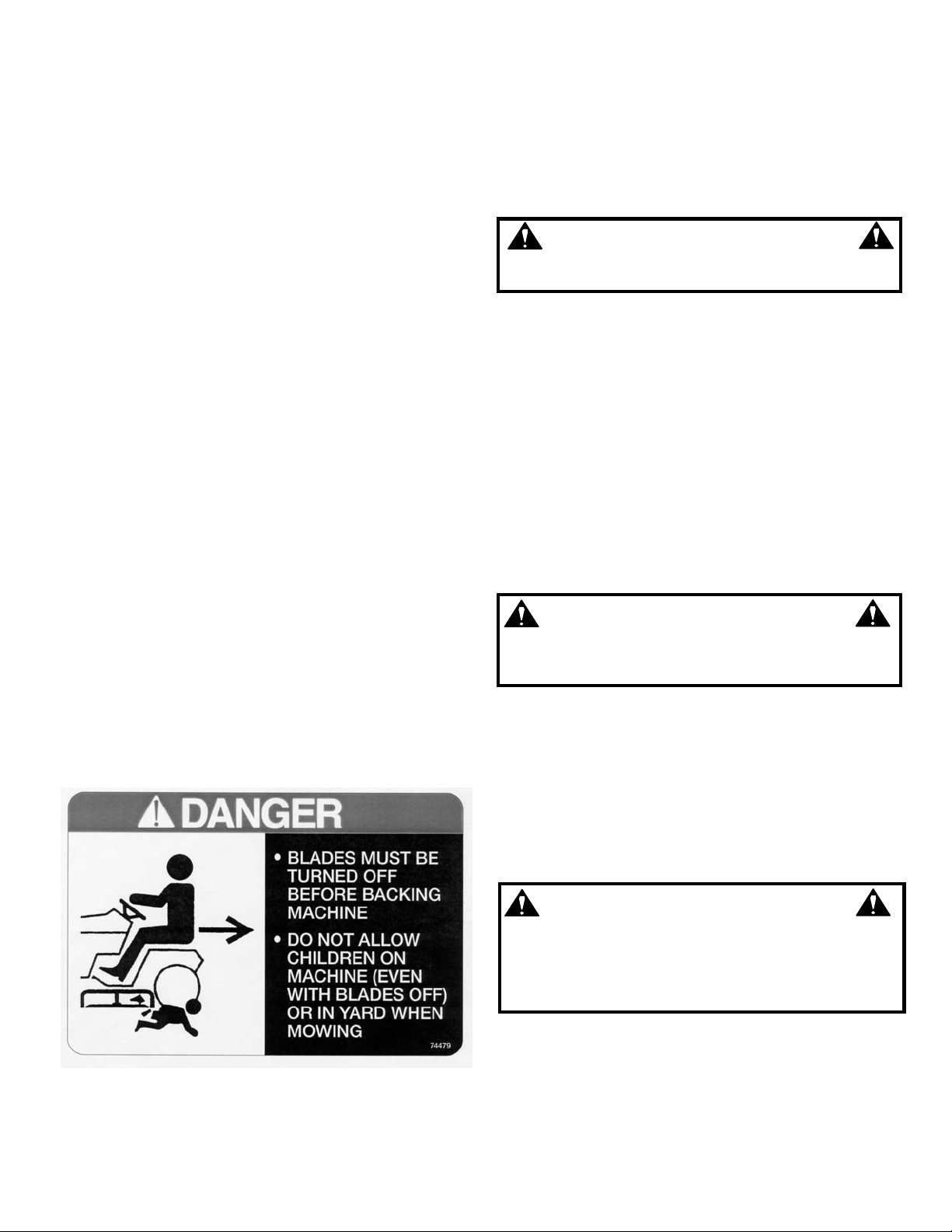
LOOK and SEE behind and down for children, pets
and hazards before and while backing.
IMPORTANT! DO NOT use the Reverse Lockout
Mechanism Override as the nor mal operating mode. To
return to the Reverse Lockout Mechanis m mode, move
the blade engagement lever down to the “OFF” position.
The Override will reset to Reverse Lockout.
2.7.2. Check the Reverse Lockout Mechanism
Before each use, check the Reverse Lockout
Mechanism for proper function. Perform the following
check with the engine “OFF”.
1. With engine “OFF”, raise blade engagement
lever to "ON".
2. The Reverse Lockout Mechanism must
prevent the speed control lever from going into
reverse.
DO NOT operate machine if Reverse Lockout
Mechanism is not functioning properly. Contact your
SNAPPER dealer immediately for assistance.
LOOK and SEE behind and down for children, pets
and hazards before and while backing.
BLADES must be turned off before backing machine.
DO NOT allow children on machine (even with
blades off) or in yard when mowing.
WARNING
WARNING
DANGER
12
Section 3 - MAINTENANCE
PICTURED
3.1 INTRODUCTION
To retain the quality of the Tractor, use genuine
SNAPPER replacement parts only. Contact a local
SNAPPER dealer for parts and ser vice assistance. For
the correct part or inform ation for a particular Tractor,
always mention the model and serial number.
SNAPPER recommends returning the Tractor to an
authorized SNAPPER dealer annually for inspection
and addition of any new devices, which might upgrade
the safety of the Tractor. For the nearest SNAPPER
dealer in your area, check the yellow pages under the
heading LAWN MOWERS. For engine parts and
service, look for the engine manufacturer’s dealers
under the heading, ENGINES - gasoline.
3.2 SERVICE - AFTER FIRST 5 HOURS
WARNING
DO NOT attempt any adjustments, maintenance or
service with the engine or blades running. STOP blades.
STOP engine. Set park brake. Remove key. Remove
spark plug wire from spark plug and secure wire away
from spark plug. Engine and components can be
extremely hot. Avoid burns by allowing engine and
components sufficient time to cool.
3.2.1. CHANGE ENGINE OIL
The engine is equipped with a Fastex™ oil drain.
1. Rotate drain body counterclockwise and pull out to
open drain. See Figure 3.1.
2. Drain oil into a 2 quart container placed beneath
end of oil drain.
3. After all oil has dr ained, push drain body "IN" and
rotate clockwise to close.
4. Fill engine with new motor oil as specified in engine
owner's manual.
“ADJUSTING MOWER BLADE”.
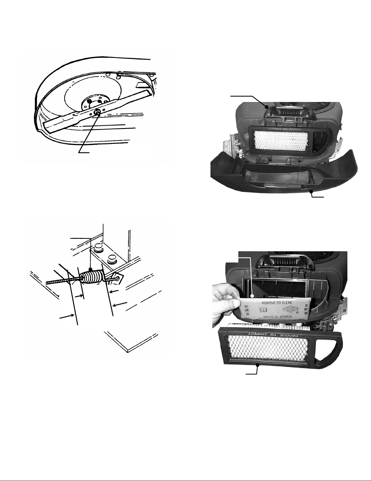
5. Check torque of blade mounting bolts. Torque to:
33” deck – 30 to 40 ft. lbs. See Figure 3.2.
38” deck – 70 to 80 ft. lbs. See Figure 3.3.
OIL
FILLER
TUBE
FASTEX™
OIL DRAIN
ROTATE COUNTERCLOCKWISE AND PULL
OUT TO OPEN.
PUSH IN AND ROTATE
CLOCKWISE TO CLOSE .
NOTE: BRIGGS &
STRATTON ENGINE
FIGURE 3.1
WARNING
The following procedure requires the engine and
blades to be operated. Exercise ext reme caution. Clear
area of loose parts & tools first. Only operate blades
when seated in the operator’s seat.
3.2.2. CHECK BLADE BRA KE
1. Check blade brake for proper function. Blades
should stop rotating in 5 seconds or less after moving
the blade engagement lever down to the OFF position.
2. If blades continue to rotate longer than 5 seconds
do not operate machine. Refer to Section “BLADE
BRAKE ADJUSTMENT” or contact your SNAPPER
dealer for assistance.
3.2.3. CHECK MOWER BLADE
1. Remove deck from tractor.
2. Carefully position deck to access blade.
3. Check blade for sharpness, wear and damage.
Refer to Section “BLADE WEAR LIMITS”.
4. Check blade for straightness. Refer to Section
TORQUE 33” BLADE TO
30 TO 40 FT. LBS.
FIGURE 3.2
WARNING
Blades must stop rotating in 5 seconds or less after
blades have been turned off . DO NOT operate machine
until blade brake has been adjusted and functioning
properly. Contact your SNAPPER dealer for assistance.
13
Section 3 - MAINTENANCE
3.2.3. CHECK MOWER BLADE (Continued)
TORQUE 38” BLADES TO
70 TO 80 FT. LBS.
FIGURE 3.3
3.2.4. CHECK 33" DECK DRIVE BELT
1. With engine "OFF", move blade engagement
lever to "ON".
2. Measure blade cable extension spring. Spring
should extend 1" +/-1/8" for proper belt tension. See
Figure 3.4.
BLADE CABLE
EXTENSION SPRING
3. To adjust tension, Refer to Section “BLADE
BELT ADJUSTMENT”.
3.2.5. CHECK 38” DECK DRIVE BELT
1. On 38" m odel, check belt for excessive wear or
damage and replace if necessary, there are no
adjustments on this model.
3.3 SERVICE - EVERY 25 OPERATING HOURS
3.3.1. CHECK ENGINE
1. Change engine oil. Refer to Section “CHANGE
ENGINE OIL”. Refer to engine owner's m anual for oil
specification.
X
X + 1” +/- 1/8”
FIGURE 3.4
2. Change air filter. Pull up and rotate the air cleaner
latch to remove cleaner cover. See Figure 3.5.
IMPORTANT: When cover is removed, you are
viewing the carburetor side of the air filter, which will
appear clean. Remove filter and pre-cleaner for
inspection.
AIR CLEANER
LATCH
AIR CLEANER
COVER
FIGURE 3.5
2. Refer to engine owner's manual for cleaning and
service instructions. Remove and clean engine air
pre-cleaner. Remove and replace engine air cleaner.
See Figure 3.6. Install pre-cleaner and air cleaner
per engine owner’s manual.
AIR PRECLEANER
AIR CLEANER
FIGURE 3.6
3. Reinstall air cleaner cover. Insert tabs located at
the bottom of the cover into corresponding slots in
engine cover. Position cover and engage latch over
cover and rotate and push down to lock.
14
Section 3 - MAINTENANCE
FUEL TANK
GEAR
3.3.2. MOWER COMPONENTS
1. Check deck drive belt for proper tension. Refer
to Section “CHECK DECK DRIVE BELT”.
2. Check blades for sharpness, wear, damage and
torque. Refer to Section “MOWER BLADE
REPLACEMENT”.
3. Check mower deck for proper levelness. Refer
to Section “MOWER DECK ADJUSTMENT LEVELNESS”.
4. Clean mower deck.
a. Remove key from ignition switch.
b. Remove deck.
c. Clean underside of mower deck, removing all
accumulation of grass clippings and debris.
d. Clean top of deck, removing all grass clippings
and debris.
5. 33" and 38” blade spindle lubrication.
a. Lubricate spindle with 1 to 3 shots of general
purpose grease from grease gun.
6. Lubricate all mower deck linkage pivot points
with a light coat of motor oil.
3.3.3. CHECK BLADE BRAKE
1. Refer to Section “CHECK BLADE BRAKE”.
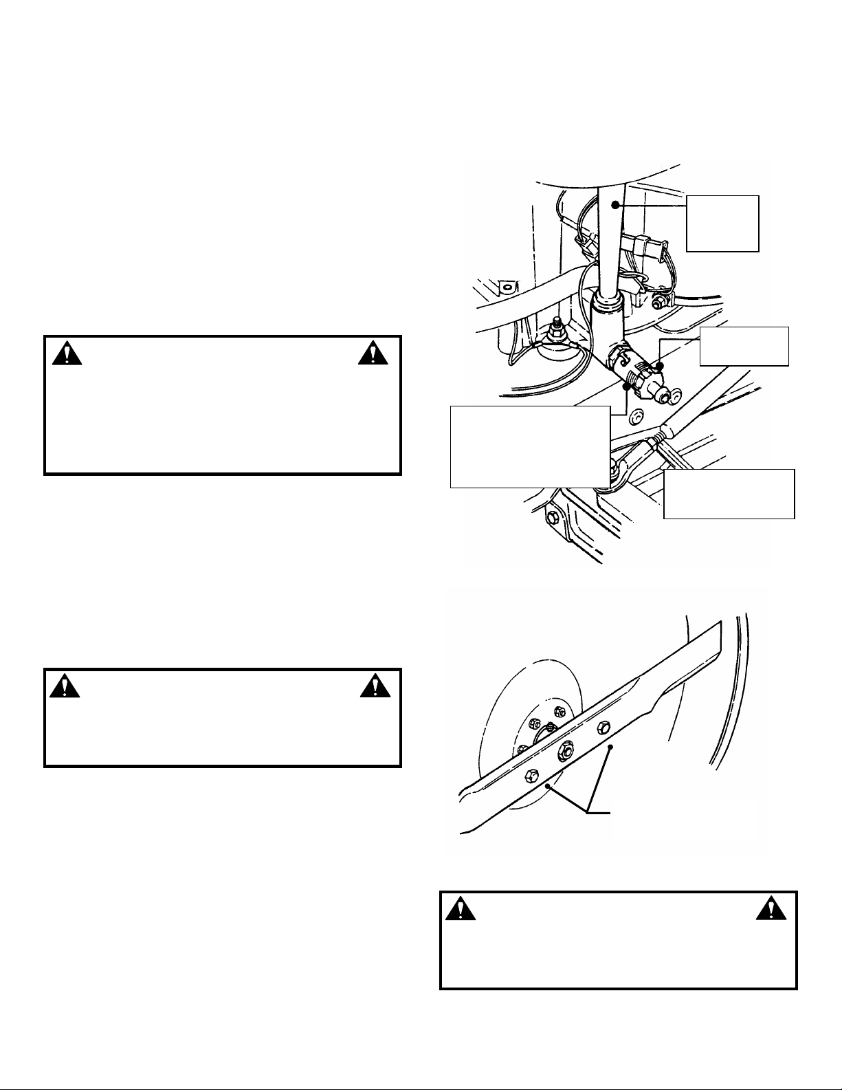
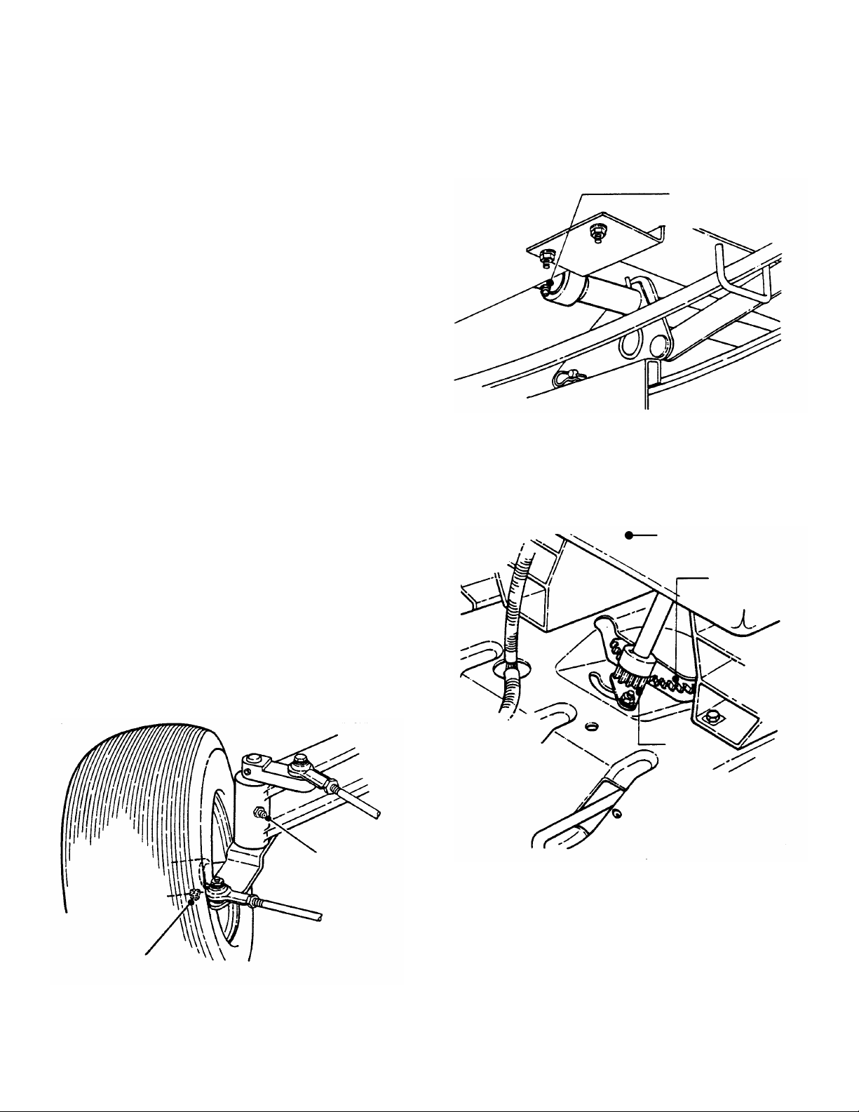
3.3.4. TRACTOR LUBRICATION
1. Front Wheel Bearings
Lubricate each front wheel bearing through the
grease fitting on wheel hub. Using general purpose
grease in a grease gun, add grease until grease
purges from bearing. See Figure 3.7.
2. Axle Spindles
Lubricate each axle spindle with 1 to 3 shots of
general purpose grease. See Figure 3.7.
NOTE: T he right hand spindle fitting faces forward and
the left hand spindle fitting faces to the rear.
3. Clutch/Brake Pivot
The clutch/brake pivot is located on the left hand
underside of the tractor and is lubricated with one
shot of general purpose grease. See Figure 3.8.
CLUTCH/BRAKE
PIVOT LUBRICATION
FITTING
FIGURE 3.8
4. Steering Sector Gear
Lubricate with a light coat of general purpose grease.
See Figure 3.9.
STEERING
SECTOR
FRONT WHEEL
BEARING LUBRICATION
FITTING
FIGURE 3.7
AXLE SPINDLE
LUBRICATION
FITTING
SECTOR
FIGURE 3.9
5. Steering Shaft
Lubricate steering shaft wear points with a light coat
of SAE30 oil.
15
 Loading...