


Smeg CW350B, CW350S, CW350BS, CW350BSD, CW400B User Manual
...LAVABICCHIERI PROFESSIONALI
PROFESSIONAL GLASSWASHERS
LAVE-VERRES PROFESSIONNELS
PROFESSIONELLER GLÄSERSPÜLER
LAVAVASOS PROFESIONAL
MÁQUINAS DE LAVAR COPOS PROFISSIONAL
CW350B CW350BS CW350BSD CW350 CW350S CW350SD CW400B CW400BS CW400BSD CW400R CW400RS CW400RSD
1Safety and usage instructions
2Technical characteristics
3Installation and positioning
4Installer – technical assistant instructions
5First startup
6Settings
7Screen-displayed anomalies (technical)
8User instructions Mod. CW400R – CW400RSD
9User Instructions Mod. CW350B-CW350BSD-CW350-CW350SD- CW400B-CW400BSD
10Maintenance and cleaning
11Problems and anomalies (user)
12Screen-displayed anomalies (user)
13Electrical - Connections scheme
Thank you for having chosen this product.
We recommend that you read all of the instructions contained in the manual attentively in order to become familiar with the most suitable conditions for the correct use of the dishwasher.
TECHNICAL INSTRUCTIONS:
Are intended for qualified personnel who will perform the installation, the setup, the testing and eventual assistance operations.
USER INSTRUCTIONS:
Indicate the recommended usage, the command descriptions and the proper cleaning and maintenance operations for the dishwasher.

1 Safety and usage instructions
THIS MANUAL CONSTITUTES AN INTEGRAL PART OF THE DISHWASHER; IT MUST NECESSARILY BE STORED INTEGRAL AND TOGETHER WITH THE APPARATUS.
THE POSITIONING, CONNECTIONS, SETUP AND TROUBLESHOOTING, AND THE SUBSTITUTION OF THE POWER CABLE MUST BE PERFORMED BY QUALIFIED
PERSONNEL.
THE DISHWASHER IS INTENDED EXCLUSIVELY FOR PROFESSIONAL USE AND MUST BE USED BY COMPETENT PERSONNEL. IT IS DESIGNED TO WASH DISHES (PLATES, CUPS, BOWLS, BAKING PANS, SILVERWARE) AND SIMILAR ITEMS FROM THE GASTRONOMY AND THE COLLECTIVE RESTAURANT INDUSTRIES. IT CONFORMS TO THE INTERNATIONAL ELECTRIC AND MECHANICAL SAFETY NORMS (CEI-EN-IEC 60335-2-58/61770) AND ELECTROMAGNETIC COMPATIBILITY NORMS (CEI-IEC-EN 55014-1/-2, 61000-3;4, 50366).
THE MANUFACTURER DECLINES ANY RESPONSABILITY FOR DAMAGE TO PERSONS OR THINGS CAUSED BY NON-OBSERVANCE OF THE INSTRUCTIONS PRESENT IN THE MANUAL, BY INCORRECT USE, BY TAMPERING EVEN WITH A SINGLE PART OF THE APPARATUS AND BY USE OF NONORIGINAL REPLACEMENT PARTS.
THE ELECTRICAL GROUNDING OF THE APPARATUS ACCORDING TO THE METHODS PRESCRIBED BY THE ELECTRICAL SYSTEM’S SAFETY NORMS IS OBBLIGATORY.
THIS APPARATUS IS MARKED IN CONFORMITY TO THE EUROPEAN DIRECTIVE 2002/96/EC, WASTE ELECTRICAL AND ELECTRONIC EQUIPMENT (WEE).
BY ENSURING THAT THIS PRODUCT BE DISPOSED OF IN A CORRECT MANNER, THE USER CONTRIBUTES TO THE PREVENTION OF POTENTIALLY NEGATIVE ENVIRONMENTAL AND HEALTH CONSEQUENCES.
THE  SYMBOL ON THE PRODUCT, OR UPON ITS ACCOMPANYING DOCUMENTATION, INDICATES THAT THIS PRODUCT MUST NOT BE TREATED AS DOMESTIC WASTE, BUT MUST BE TAKEN TO A SUITABLE COLLECTION DEPOT FOR THE RECYCLING OF ELECTRIC AND ELECTRONIC APPARATUS. DISPOSE OF THE APPARATUS ACCORDING TO THE LOCAL WASTE DISPOSAL NORMS.
FOR MORE INFORMATION ON THE TREATMENT, RECOVERY AND RECYCLING OF THIS PRODUCT, CONTACT YOUR COMPETENT LOCAL AUTHORITY, YOUR DOMESTIC WASTE DISPOSAL SERVICE OR THE STORE IN WHICH THE PRODUCT WAS PURCHASED.
DO NOT INSERT SOLVENTS SUCH AS ALCOHOL OR TURPENTINE WHICH COULD PROVOKE EXPLOSIONS. DO NOT INSERT DISHES WITH RESIDUES OF ASH, WAX OR VARNISH.
NEVER USE THE DISHWASHER OR ITS PARTS AS A STEP-LADDER, SUPPORT OR BRACE FOR PERSONS, THINGS OR ANIMALS.
LEANING OR SITTING UPON THE DISHWASHER’S OPEN DOOR COULD CAUSE IT TO TIP, WITH CONSEQUENT PERSONAL DANGER.
DO NOT LEAVE THE DISHWASHER’S DOOR OPEN IN ORDER TO AVOID TRIPPING UPON IT.
DO NOT DRINK THE RESIDUAL WATER EVENTUALLY PRESENT IN THE DISHES OR IN THE DISHWASHER AFTER A WASH CYCLE.
THE APPARATUS IS NOT ADAPTED FOR USE BY MINORS AND PEOPLE WITH REDUCED PHYSICAL, SENSORIAL OR MENTAL CAPABILITIES WITHOUT EXPERIENCE OR FAMILIARITY WITH THE DEVICE. THE USE OF THE APPARATUS IS PERMITTED TO THESE PEOPLE ONLY UNDER THE SUPERVISION OF A PERSON IN CHARGE OF THEIR SAFETY.
2
2 |
Technical characteristics |
|
|
|||
|
|
|
|
|
|
|
|
|
TECHNICAL CHARACTERISTICS |
|
|
||
|
|
|
CW350B |
CW350 |
CW400B |
CW400R |
|
|
|
CW350BS |
CW350S |
CW400BS |
CW400RS |
|
|
|
CW350BSD |
CW350SD |
CW400BSD |
CW400RSD |
Input voltage power |
|
V |
230V/1 |
230V/1 |
230V/1 |
400V 3N ~ |
|
|
|
|
|
|
|
Frequency |
|
Hz |
50 |
50 |
50 |
50 |
|
|
|
|
|
|
|
Max. absorbed power |
|
kW |
2,9 |
2,9 |
2,9 |
4,8 |
|
|
|
|
|
|
|
Boiler resistance power |
|
kW |
2,6 |
2,6 |
2,6 |
4,5 |
|
|
|
|
|
|
|
Tank resistance power |
|
kW |
1,6 |
1,6 |
1,6 |
1,6 |
|
|
|
|
|
|
|
Wash pump power |
|
kW |
0,3 |
0,3 |
0,3 |
0,3 |
|
|
|
|
|
|
|
Water supply pressure |
|
kPa (bar) |
200-400 (2 ÷ 4) |
200-400 (2 ÷ 4) |
200-400 (2 ÷ 4) |
200-400 (2 ÷ 4) |
|
|
|
|
|
|
|
Water supply temperature |
|
°C |
50°C – 60°C |
50°C – 60°C |
50°C – 60°C |
50°C – 60°C |
|
|
|
|
|
|
|
“S” versions Water supply |
|
|
|
|
|
|
temperature (incorporated water- |
|
°C |
15°C – 30°C |
15°C – 30°C |
15°C – 30°C |
15°C – 30°C |
softener) |
|
|
|
|
|
|
Water supply hardness |
|
°dF |
7°dF-12°dF |
7°dF-12°dF |
7°dF-12°dF |
7°dF-12°dF |
|
|
|
|
|
|
|
Rinse cycle water consumption |
|
l |
2,4 |
2,4 |
2,4 |
3,5 |
|
|
|
|
|
|
|
Boiler capacity |
|
l |
2,7 |
2,7 |
3,9 |
5,5 |
|
|
|
|
|
|
|
Tank capacity |
|
l |
10 |
10 |
14 |
35 |
|
|
|
|
|
|
|
Standard cycle duration with |
|
s |
120/180 |
120/180 |
120/180 |
60/120/180/C |
water supply at 50°C |
|
|||||
|
|
|
|
|
|
|
Noise level |
|
dB(A) |
56 |
56 |
56 |
56 |
|
|
|
|
|
|
|
Protection rating |
|
IPX |
4 |
4 |
4 |
4 |
|
|
|
|
|
|
|
Net weight |
|
kg |
31 |
37 |
44 |
53 |
|
|
|
|
|
|
|
Power cable type |
|
◄HAR► |
H05VV-F |
H05VV-F |
H05VV-F |
H07RN-F |
|
|
|
|
|
|
|
NOTE: “D” = versions with integrated detergent metering unit – “S” versions with integrated water-softener
3 Installation and positioning
INSTALLATION and POSITIONING
Bring the dishwasher to its installation location, remove its packaging and verify the integrity of the apparatus and of the components. If damaged, written notification must be sent to the transporter.
The packaging elements (plastic bags, polystyrene foam, nails, etc) must not be left within reach of children and domestic animals as they are a potential source of danger.
All of the materials used for packaging are compatible with the environment. They may be safely preserved, or may be disposed of at an appropriate waste disposal facility.
The components in plastic material subject to eventual disposal through recycling are marked in the following manner:
PE polyethylene: external wrapping, instructions bag, protection bags.
PP polypropylene: bands.
PS polystyrene foam: protective corners, packaging cover.
3

The wood and cardboard components can be disposed of by respecting the norms in vigor.
When disposing of the product, avoid leaving it in the environment; its disposal must respect the norms in vigor. All of the metallic parts are in stainless steel and are detachable.
The plastic parts are marked with the symbol of the relative material.
POSITIONING:
Warning: the internal system and the locations in which communal apparatus are to be installed, must answer to the norms in vigor.
The manufacturer declines any responsibility for direct damages to persons of things deriving from lack of respect for the said norms.
Prior to installation verify that objects and materials which could be damaged by aqueous vapor or by spray from washing solutions are not in the vicinity, or are adequately protected.
Position the dishwasher in the desired position and remove the protective wrapping.
Level the dishwasher (with the help of a level) on its four feet, regulating them in such a way so as to guarantee stability; any alternate solution must be approved by the manufacturer.
4INSTALLER – TECHNICAL ASSISTANT INSTRUCTIONS
Water and drain connection:
The water tubes and the electrical power cable stick out from the back of the machine. Connect the water supply tube to a ¾” threaded gas outlet.
Use only new tubes for the connection to the water supply; old or used tubes must not be utilized.
The dynamic supply pressure must be between 2 and 4 bar; if the pressure is higher, a pressure reducer must be installed.
It is indispensable to install a general faucet on the supply water input tubing; the faucet must be accessible after installation has been completed. Do not install the faucet behind the dishwasher.
The declared cycle durations refer to a 50° hot water supply.
Where a cold water supply is used, the duration of the cycle could increase in relation to the input water temperature since the dishwasher is equipped with a constant temperature and pressure rinse system.
Drain:
Every dishwasher comes equipped with a drain connection tube; this is prescribed to be at floor level, with a trap drain.
Caution: make sure that the supply and drain tubes are not bent, restricted or crushed after installation.
4.1 Electrical connection
The dishwasher’s electrical connection and that of eventual supplementary apparatus is to be entrusted to authorized and qualified personnel, with respect to the norms in vigor; observe also the technical regulations for the connections.
The total power installed is given upon the apparatus’ technical data label. Other apparatus must not be protected along with the dishwasher.
The user must provide for the installation, according to the norms in vigor, of a main electrical power switch and of a differential switch compatible with the machine’s characteristics.
These switches must be installed near the dishwasher, be easily accessible after installation and guarantee complete disconnection from the electrical supply in category III overvoltage conditions.
Caution!!!
The dishwasher is free of electrical current only when the main switch is off.
Connect the apparatus to the usage equalizer. The  clamp for the connection is located at the lower
4

back of the machine.
The protection conductor (PE) is yellow-green in color, the neutral conductor (N) is blue and the phase conductors (L1, L2, L3) are black, gray and brown.
5 FIRST STARTUP
FIRST STARTUP
The electrical protection system must be subjected to a functional test before use. The installation must be performed and/or verified by the authorized reseller who will be responsible for the first startup and the instructions relative to the dishwasher’s operation.
PREPARATION FOR USE
Important:
The rinse-aid metering unit comes equipped in all models while the detergent metering unit comes equipped in only some models.
If both metering units are present position the external detergent and rinse-aid containers and insert their respective suction tubes located at the back of the machine. Red tube: detergent
Transparent tube: rinse-aid
Before inserting the tubes in the containers apply the weight (necessary to keep the tube at the bottom of the container) and the filter as indicated in the diagram.
For adjustments, use the adjustment screws indicated in the diagram. It is recommended that adjustments be performed by personnel from the companies who have supplied the detergent products.
If the detergent metering unit did not come pre-installed it can be installed at a later time by ordering the relative KIT.
Alternatively, an external metering unit can be connected by means of an electrical connection with a 2x0.5 mm type H05 RN-F cable. This cable must be inserted through the passage indicated in the TECHNICAL CHARACTERISTICS scheme and connected in accordance with the electrical scheme furnished with the dishwasher.
The metering unit must be of 230V/50Hz with a maximum absorbed power of 15W. Connect the detergent metering unit to the dishwasher through the red tube cited above.
6 SETTINGS (only models CW400RSD - CW400R – CWC500R)
SETTINGS
During the first startup, arrange for the setup or the adjustment of the functions/parameters indicated hereafter:
POWER SUPPLY: 200 – 250 VAC.
ABSORBED POWER : 4 VA
OPERATIONAL TEMPERATURE: 0 / 60 °C
OPERATIONAL HUMIDITY: max 90 % without condensation
NORMS: The control unit is designed and manufactured in observance of the
European norms in vigor regarding electrical safety and electromagnetic compatibility.
Particularly the following:
EN 61000-6-3 : Emissions for residential and commercial environments
EN 61000-6-2 : Immunity for industrial environments
EN 61000-4-11 : Immunity to supply micro-interruptions
EN 60335-1 : Low voltage safety directive
5
ZERO CROSSING : The relay which powers the Tank’s electrical resistance is equipped with the “ zero crossing “ function which synchronizes the switching of this relay, both in closing and in opening, with the voltage supply’s passing to zero both for 50 Hz and 60 Hz frequencies. In this manner the relay’s contacts usage is significantly reduced.
CONNECTION SCHEME
Clamp |
Connection for model. CWC500R |
Connection for models CW400RSD – CW400R |
|
|
|
1 – 2 |
CONTROL UNIT POWER SUPPLY, 230 VAC |
CONTROL UNIT POWER SUPPLY, 230 VAC |
|
|
|
3 – 4 |
BOILER TEMPERATURE SENSOR |
BOILER TEMPERATURE SENSOR |
|
|
|
5 – 6 |
TANK TEMPERATURE SENSOR |
TANK TEMPERATURE SENSOR |
|
|
|
10 |
BREAK-TANK PRESSOSTAT |
BREAK-TANK PRESSOSTAT |
|
|
|
11 |
Reserve input |
SALT CONTAINER SENSOR |
|
|
|
12 |
MICRO HOOD |
MICRO DOOR |
13 |
TANK PRESSOSTAT, closed over level |
TANK PRESSOSTAT, closed over level |
|
|
|
14 |
COMMON INPUTS |
COMMON INPUTS |
|
|
|
15 |
BOILER RESISTANCE REMOTE CONTROL SWITCH COIL |
BOILER RESISTANCE REMOTE CONTROL SWITCH COIL |
|
|
|
16 |
TANK RESISTANCE, max. 10 Amp. |
TANK RESISTANCE, max. 10 Amp. |
|
|
|
17 |
- |
REGENERATION ELECTROVALVE |
|
|
|
18 |
- |
COLD RINSE ELECTROVALVE |
|
|
|
18 B.TANK |
RINSE PUMP (MACHINE TYPE 4) |
RINSE PUMP (MACHINE TYPE 4) |
|
|
|
19 |
WASH PUMP ( max. 1 HP ) |
WASH PUMP ( max. 1 HP ) |
|
|
|
20 |
RINSE ELECTROVALVE + PRESSURE INCREASE PUMP |
RINSE ELECTROVALVE + PRESSURE INCREASE PUMP |
|
|
|
21 |
DRAIN PUMP ( max. 0.75 HP ) Optional |
DRAIN PUMP ( max. 0.75 HP ) Optional |
|
|
|
22 |
OUTPUT POWER SUPPLIES, 230 VAC phase |
OUTPUT POWER SUPPLIES, 230 VAC phase |
6
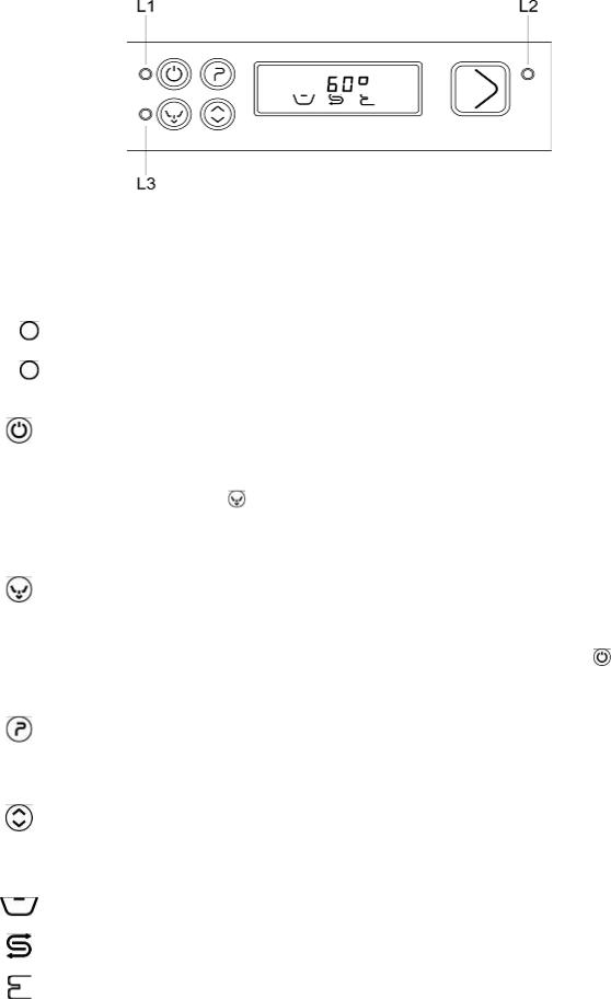
KEYBOARD FUCNTIONALITY CW400RSD – CW400R
MAIN FUNCTIONS WITH MACHINE POWERED
ITEM |
Description |
Function |
|
|
|
|
|
|
|
L1 |
Machine powered |
This led indicator turns on (green) when electrical current is present |
||
led indicator |
||||
|
|
|
||
L2 |
Tank emptying led |
This led indicator (green) indicates that the machine is emptying the |
||
indicator |
Tank – the led flashes when the operation is in progress. |
|
||
|
|
|||
|
|
Pressing this button with led indicator 1 on activates the keyboard |
||
|
On/Off button |
and renders the machine operational. |
|
|
|
The last program used (wash cycles) will be shown on the 3 |
|
||
|
|
|
||
|
|
displays when turned on. |
|
|
|
|
To empty the Tank first remove the Tank’s overflow, then press the |
||
|
|
button for 3 seconds. This inhibits water from being loaded and, |
||
|
|
after a Pressostat Tank-empty signal verifies that the Tank has |
||
|
|
been emptied, will only allow a limited amount of boiler water to |
||
|
Tank emptying |
circulate in order to facilitate the cleaning of the Tank. |
|
|
|
At the end of the function the machine goes into a stand-by phase |
|||
|
button |
|||
|
|
which is indicated by the appearance of three dashes “---“ upon the |
||
|
|
displays. To render the machine operational again it is therefore |
||
|
|
necessary to insert the Tank’s overflow and to press the |
button. |
|
|
|
If the machine is equipped with the drain pump option, the drain |
||
|
|
pump will also be activated. |
|
|
|
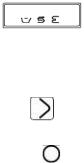
Programs button |
By repeatedly pressing this button the various wash cycles can be |
||
|
viewed (brief 60”, medium 120”, long 180”, continuous) |
|
||
|
|
|
||
|
|
The use of this button does the following, in sequence: |
|
|
|
|
• Enables the “crystal cycle” only with the medium cycle 120” |
||
|
|
(“C” on the display”); Sets the T of the boiler from 85°C to |
||
|
OPTIONS button |
70°C |
|
|
|
|
• Enables regeneration (rig on the display) if decal is |
|
|
|
|
installed. (if a program has not been set, it will not be |
||
|
|
performed) |
|
|
|
Tank led indicator |
Indicates, when on, that the temperature shown during washing is |
||
|
that of the Tank. |
|
||
|
|
|
||
|
Salt led indicator |
Indicates insufficient salt quantity (if prescribed in the function) |
||
|
The led indicator turns on for the closing of a reed contact. |
|
||
|
|
|
||
|
Boiler led indicator |
Boiler resistance in function symbol |
|
|
|
|
|
|
|
7
|
|
Can indicate the program which will begin and the boiler/Tank |
|
|
|
temperature. |
|
|
|
In case of anomalies an error code will be indicated, for example |
|
|
|
“E 1” |
|
|
3 DISPLAY |
- Boiler temperature anomaly |
|
|
|
- Tank temperature anomaly |
|
|
|
- Tank loading anomaly |
|
|
|
- Tank draining anomaly |
|
|
|
- Boiler anomaly |
|
|
Start button |
Initiates the program shown on the display |
|
|
|
|
|
|
|
This led indicates the state of the machine |
|
L3 |
Bicolor led indictor |
• Green indicates the machine is ready for a new program |
|
• Red indicates the machine is busy with an operation |
|||
|
|
||
|
|
• Yellow indicates a break after Tank draining |
MACHINE CONFIGURATION PARAMETERS (Intended for technical personnel, not the user)
Parameter |
Description |
Range |
Preset |
|
P0 |
Drain cycle time |
1-5’ |
1 |
|
P1 |
Boiler temperature |
60-95°C |
82 |
|
P2 |
Tank temperature |
40-65°C |
55 |
|
P3 |
Rinse duration |
10-40’’ |
13 |
|
P4 |
BOILER STOP option |
YES/NO |
1 YES |
|
P5 |
Brief wash time |
60-90 |
60 |
|
P6 |
Drain with overflow option |
YES/NO |
1 |
YES |
P7 |
Cold rinse option |
YES/NO |
0 |
NO |
P8 |
Regeneration option |
YES/NO |
1 YES |
|
P9 |
Maximum water load duration |
1-10’ |
10 |
|
P10 |
H2O Hardness (to be set by the user based on water hardness) |
35 |
15 |
|
P11 |
Machine type |
4 |
4 |
|
P12 |
Wash number counter |
YES |
1 YES |
|
PARAMETER FUNCTION WITH MACHINE ON
Upon first installation it is possible to perform a series of operations which allow for the personalization of the dishwasher based on the user’s necessities, as well as a test cycle which quickly checks the functionality of all of the components. To perform these operations it is necessary to set the machine to “programming mode” as described hereafter
Shut the machine off by pressing 
Simultaneously press  and
and  until P0 appears on the display
With the  button (ahead) and the
  button (back) select the programs
Once the parameter to modify has been identified, keep the  button pressed and modify the required setting with the “ahead”
  and “back”
  buttons
Once the setting has been correctly modified, release the  button
When finished with the settings turn the machine off and on again by pressing 
Note: always turn on the DRAIN PUMP function in machines with Air Tank or Break Tank even if absent.
IN PARAMETERIZATION MODE, IF NO BUTTON IS PRESSED WITHIN 30 SECONDS THE KEYBOARD SHUTS DOWN AND RETURNS TO ITS OFF STATE.
8
Regeneration mode:
Once having reached the set number of cycles, at the end of the last cycle (ex. The 20th or the 35th, etc.) the message rig will appear flashing on the display for 10”; of it is desired to continue and the request is ignored, the message will appear for 10” at the end of every cycle.
The regeneration phase only begins after the Tank Pressostat has arrived at empty
1)EVR active for 20”, 1’ break – repeat EV regenerate activation 4 times
2)8’ break
3)EV1 active for 25”, 1’ break - repeat EV load activation 4 times, PS activation (drain pump) contextually to EV load + 5”
Afterwards, once the first samples are available, verify the correctness of the times/actual regeneration and proper resin washing.
At the end of the regeneration, the display goes back to showing the last program performed and the machine is once again ready for use.
Note: the regeneration cycle can be cancelled once initiated by keeping the  button pressed for 10 seconds.
7 SCREEN DISPLAYED ANOMALIES
After having turned the machine off and on again, if the problem persists communicate the type of error displayed on the screen to technical assistance:
E1 |
Boiler sensor malfunction |
|
|
E2 |
Tank sensor malfunction |
|
|
E3 |
Water loading timeout ( the water loading duration has exceeded the set time ) |
|
|
|
Draining anomaly. At the end of the draining phase the CPU still detects water in the Tank. This may be |
E6 |
due to: Drain pump malfunction (if present), drain tube blockage, Tank Pressostat malfunction, drain |
|
cycle time set too low, Tank overflow inserted |
|
|
E7 |
30 minute Tank timeout |
|
|
E8 |
15 minute boiler timeout |
|
|
9
 Loading...