


Index
1.PRECAUTIONS FOR SAFETY AND USE _____________________ 36
2.INSTALLING THE APPLIANCE _____________________________ 38
3.DESCRIPTION OF CONTROLS ____________________________ 40
4.HOB __________________________________________________ 47
5.USING THE OVEN_______________________________________ 52
6.ACCESSORIES AVAILABLE _______________________________ 53
7.COOKING ADVICE ______________________________________ 54
8.CLEANING AND MAINTENANCE ___________________________ 62
9.EXTRAORDINARY MAINTENANCE _________________________ 65
INSTRUCTIONS FOR THE INSTALLER: these are intended for the qualified engineer who is to install, commission and test the appliance.
INSTRUCTIONS FOR THE USER: these provide recommendations for use, a description of the controls and the correct procedures for cleaning and maintaining the appliance.
35
Introduction
1. PRECAUTIONS FOR SAFETY AND USE
THIS MANUAL IS AN INTEGRAL PART OF THE APPLIANCE. TAKE GOOD CARE OF IT AND KEEP IT TO HAND THROUGHOUT THE COOKER'S LIFE CYCLE. USERS ARE ADVISED TO READ THIS MANUAL AND ALL THE INSTRUCTIONS IT CONTAINS BEFORE USING THE COOKER. INSTALLATION MUST BE CARRIED OUT BY QUALIFIED STAFF IN COMPLIANCE WITH THE RELEVANT REGULATIONS. THIS APPLIANCE IS INTENDED FOR HOUSEHOLD USE AND COMPLIES WITH THE EEC DIRECTIVES CURRENTLY IN FORCE. THE APPLIANCE IS BUILT TO PROVIDE THE FOLLOWING FUNCTION: COOKING AND HEATING FOODS; ALL OTHER USES ARE TO BE CONSIDERED IMPROPER.
THE MANUFACTURER DECLINES ALL LIABILITY FOR USES OTHER THAN THOSE STATED ABOVE.
NEVER LEAVE PACKAGING RESIDUES UNATTENDED IN THE HOME. SEPARATE WASTE PACKAGING MATERIALS BY TYPE AND CONSIGN THEM TO THE NEAREST SEPARATE DISPOSAL CENTRE.
THE APPLIANCE MUST BE CONNECTED TO EARTH IN COMPLIANCE WITH ELECTRICAL SYSTEM SAFETY REGULATIONS.
THE PLUG TO BE CONNECTED TO THE POWER SUPPLY LEAD AND THE RELATIVE SOCKET MUST BE OF THE SAME TYPE AND COMPLY WITH THE RELEVANT REGULATIONS.
THE POWER SUPPLY SOCKET MUST BE ACCESSIBLE EVEN AFTER THE APPLIANCE HAS BEEN BUILT-IN.
NEVER DISCONNECT THE PLUG BY PULLING ON THE POWER SUPPLY LEAD.
IMMEDIATELY AFTER INSTALLATION, CARRY OUT A QUICK TEST ON THE APPLIANCE FOLLOWING THE INSTRUCTIONS PROVIDED LATER IN THIS MANUAL. IF THE APPLIANCE FAILS TO OPERATE, DISCONNECT IT FROM THE ELECTRICAL MAINS AND CONTACT YOUR NEAREST SERVICE CENTRE.
NEVER ATTEMPT TO REPAIR THE APPLIANCE YOURSELF.
AFTER EACH USE OF THE HOB, ALWAYS CHECK THAT THE CONTROL KNOBS ARE TURNED TO 0 (OFF).
NEVER PLACE FLAMMABLE OBJECTS IN THE OVEN: IF IT SHOULD ACCIDENTALLY BE SWITCHED ON, THIS MIGHT CAUSE A FIRE.
36
Introduction
THE NAMEPLATE WITH THE TECHNICAL DATA, SERIAL NUMBER AND MARK IS IN A VISIBLE POSITION IN THE STORAGE COMPARTMENT.
THE NAMEPLATE MUST NEVER BE REMOVED.
THIS APPLIANCE MUST NEVER BE INSTALLED ON A STAND.
THE APPLIANCE BECOMES VERY HOT DURING USE. TAKE CARE NOT TO TOUCH THE HEATING ELEMENTS INSIDE THE OVEN.
NEVER PLACE PANS WITH BOTTOMS WHICH ARE NOT PERFECTLY FLAT AND SMOOTH ON THE HOB.
NEVER USE THE HOB AS A WORK-TOP.
WARNING: IF YOU NOTICE A CRACK IN THE CERAMIC HOB, DISCONNECT THE APPLIANCE FROM THE ELECTRICITY SUPPLY AND CONTACT A SERVICE CENTRE.
THE USE OF THIS APPLIANCE IS NOT PERMITTED TO PEOPLE (INCLUDING CHILDREN) OF REDUCED PHYSICAL AND MENTAL ABILITY, OR LACKING IN EXPERIENCE IN THE USE OF ELECTRICAL APPLIANCES, UNLESS THEY ARE SUPERVISED OR INSTRUCTED BY ADULTS OR PEOPLE RESPONSIBLE FOR THEIR SAFETY.
THIS APPLIANCE IS TAGGED UNDER EUROPEAN DIRECTIVE 2002/96/EC ON WASTE ELECTRICAL AND ELECTRONIC EQUIPMENT (WEEE).
THIS DIRECTIVE CONTAINS THE REGULATIONS GOVERNING THE COLLECTION AND RECYCLING OF DECOMMISSIONED APPLIANCES THROUGHOUT THE EUROPEAN UNION.
BEFORE THE APPLIANCE IS PUT INTO OPERATION, ALL THE LABELS AND PROTECTIVE FILMS APPLIED INSIDE OR OUTSIDE MUST BE REMOVED.
The manufacturer declines all responsibility for injury or damage caused by failure to comply with the above regulations or deriving from tampering with even just one part of the appliance and the use of nonoriginal spare parts.
37

Instructions for the Installer
2. INSTALLING THE APPLIANCE
This appliance has fire protection (type Y) and can be installed against walls higher than the work surface.
In compliance with Electromagnetic Compatibility regulations, the electromagnetic induction hob is classified in Group 2 and Class B (EN 55011)
2.1 Electrical connection
Check that the voltage and size of the power supply line are as specified on the nameplate inside the storage compartment. This nameplate must never be removed.
The appliance's power supply line must be fitted with an omnipolar breaking device with contact gap of at least 3 mm, located in an easily accessible position close to the appliance itself.
The appliance has a terminal board on its rear for the electrical connection (see diagram below). To access it, remove the back cover.
38
Instructions for the Installer
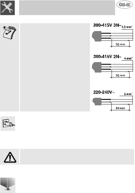
Operation at 380-415V3N~: use a H05RR-
F five-wire cable (cable of 5 x 2.5 mm2).
Operation at 380-415V2N~: use a H05RR-
F four-wire cable (cable of 4 x 4 mm2).
Operation at 220-240 V~: use a H05RR-F / H05RNF three-wire cable (cable of 3 x 6 mm2).
The earth wire (yellow-green) must be at least 20 mm longer than the other wires at the end for connection to the appliance.
The power supply cable must be fitted with a suitable five-pin plug (see technical data plate) or, for appliances operating on 220-240V , a threepin plug. The power supply plug and wall socket must be of the same type (in compliance with CEI standards). The appliance must be earthed appropriately. Before connecting it, check that the power supply line is properly earthed. The use of reductions, adapters or junctions is not recommended.
The manufacturer declines all responsibility for injury or damage caused by failure to comply with the above regulations or deriving from tampering with even just one part of the appliance.
2.2 Levelling
Level the appliance by means of its four adjustable feet. To make the adjustment, undo the lock-nut and unscrew the foot. The adjuster screw travel is 10 mm.
39
Instructions for the User
3. DESCRIPTION OF CONTROLS
3.1 The front panel
All the cooker's control and monitoring devices are placed together on the front panel.
At first use after a power blackout, press the middle knob  for 1 - 2 seconds to enable oven cooking operations.
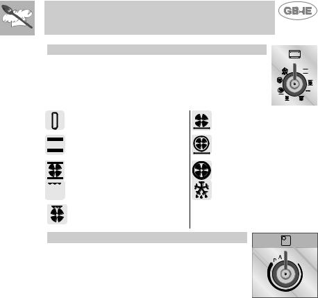
KEY TO SYMBOLS
OVEN THERMOSTAT |
CENTRAL |
|
COOKING ZONE |
OVEN FUNCTIONS |
RIGHT REAR |
|
COOKING ZONE |
LEFT FRONT |
RIGHT FRONT |
COOKING ZONE |
COOKING ZONE |
LEFT REAR |
|
COOKING ZONE |
|
THERMOSTAT KNOB
The cooking temperature is selected by turning the knob clockwise to the required setting, between 50° and 250°C. The light comes on to indicate that the oven is heating up. This light goes out when the set temperature is reached. When it flashes at regular intervals, the temperature inside the oven is being kept constantly at the set level.
40
Instructions for the User
FUNCTION SELECTOR KNOB
Turn the knob to select one of the following functions:
NO FUNCTION SET |
BOTTOM HEATING |
|
ELEMENT + FAN |
TOP AND BOTTOM HEATING |
BOTTOM HEATING |
ELEMENTS |
ELEMENT + FAN HEATING |
|
ELEMENT |
TOP AND BOTTOM HEATING |
FAN HEATING ELEMENT + |
ELEMENTS + FAN FUNCTION |
FAN |
GRILL ELEMENT |
DEFROSTING |
GRILL ELEMENT + FAN |
|
HOB CONTROL KNOB
These knobs provide control of the ceramic hob's cooking zones.
The zone it controls is shown above each knob. The knob shown on the right is for the rear left-hand cooking zone.
Turn the knob to the right to set the zone's operating power; the settings range from a minimum of 1 to a maximum of 9.
The working power is shown by a display on the hob.
41

Instructions for the User
Heating accelerator
Each cooking zone is equipped with a heating accelerator.
This system allows the zone to be operated at peak power for a time proportional to the heating power selected.
To start the heating accelerator, turn the knob to the left, select setting “A” and then release. The letter “A” will appear on the display on the hob.
You now have 3 seconds to select the heating setting of your choice. Once a setting between 1 and 9 has been selected, “A” and the chosen setting will flash in alternation on the display.
While the heating accelerator is in operation, the heating level can be increased at any time. The "full power" time will be modified accordingly. If the power is reduced by turning the knob anticlockwise, option "A" is automatically deactivated.
Power Function
The power function allows the user to operate each heating zone continuously at the maximum power for a time of no more than 10 minutes. This function can be used, for example, to bring a large amount of water to the boil in a hurry, or to turn up the heat under meat.
Turn the knob clockwise and set heating level 9, then use the knob to set the "P" position and release it. "P" appears on the corresponding zone display.
After 10 minutes, the power is reduced automatically, the knob returns to the 9 setting and the "P" disappears.
However, the power function can be turned off at any time by reducing the heating level.
When the power function is selected for one heating zone (e.g. the left front zone), the power absorbed by the second zone (left rear zone) might be reduced to supply the maximum available energy to the first zone.
Consequently, the power function takes priority over the heating accelerator.
If a pan is removed from the cooking zone while the power function is on, the function is switched off.
42
Instructions for the User
3.2 Electronic Analogue Clock (on some models only)
 LIST OF FUNCTIONS
MINUTE-MINDER BUTTON
END OF COOKING BUTTON
CLOCK TIME ADJUSTMENT AND RESET
VALUE DECREASE BUTTON
VALUE INCREASE BUTTON
3.2.1 Setting the time
When the oven is used for the first time, or after an interruption in the
electricity supply, the display flashes at regular intervals. Press the 

 key for 1 / 2 seconds to stop the display flashing and start the procedure
for setting the current time. Press the value modification keys 

 or
or 

 to increase or decrease the setting by one minute for each pressure.
Press one of the two value modification keys until the current time appears. 6/7 seconds after the last key is pressed, the clock will start from the time set.
At the end of each programmed operation 8 beeps will sound 3/4 times at intervals of about 1 and a half minutes. This sequence can be stopped at any time by pressing any key.
43
Instructions for the User
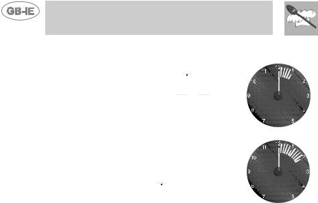
3.2.2Minute-Minder
-This function does not stop cooking; it simply activates the buzzer. Press the 

 key and the display will light up as shown in figure 1;
-Within 6/7 seconds, press the 

 or
or 

 keys to set the minute-minder. Each time a key is pressed, 1 outside segment, representing 1 minute of cooking time, will light up or go out. (figure 2 shows a cooking time of 10 minutes).
-6/7 seconds after the last key is pressed, the countdown will start; when it finishes, the buzzer will sound.
-During the countdown, the current time can be viewed by pressing the 

 key once; press it again to return to the minute minder display.
-At the end of the countdown, the oven must be switched off manually by turning the thermostat and function selector knob to 0.
 1
1
 2
2
44
 Loading...