


SMC Networks EX9-AC -1, EX9-AC -7, EX250-SEN1, EX9-AC002-3, EX500-AP -S User Manual
...Reduced wiring system
EtherNet/IP™ Compatible SI Unit
Instruction Manual
EX250-SEN1
URL http:// www.smcworld.com
Specifications are subject to change without prior notice and any obligation on the part of the manufacturer. EtherNet/IP™ is a trademark used under licence by ODVA.
The descriptions of products shown in this document may be used by the other companies as their trademarks. © 2006 SMC Corporation All Rights Reserved

Thank you for purchasing the SMC reduced wiring system EX250 series.
Please read this instruction manual carefully and understand the contents before use so that you can operate this unit safely and correctly.
Please keep this manual handy for future reference.
OPERATOR
 This instruction manual has been written for those who have knowledge of machines and equipments that use reduced wiring system as well as the sufficient knowledge to assemble, operate, and maintain such devices.
maintenance, please read this manual carefully and understand the contents.
To facilitate recycling, this |
|
manual is printed using |
This manual is printed in the |
biodegradable soy ink, which |
"non-water system", which does |
can easily be de-inked. |
not output toxic liquid waste. |
Contents |
|
SAFETY .......................................................................................................... |
2 |
Product Summary............................................................................................ |
5 |
SI Unit |
|
Model Indication Method............................................................................... |
6 |
Part Names ................................................................................................... |
6 |
Dimensions ................................................................................................... |
7 |
Mounting/Installation ..................................................................................... |
7 |
Specifications.............................................................................................. |
10 |
Wiring.......................................................................................................... |
12 |
Display/Setting ............................................................................................ |
15 |
Input Block |
|
Model Indication Method............................................................................. |
18 |
Part Names ................................................................................................. |
18 |
Dimensions ................................................................................................. |
19 |
Mounting/Installation ................................................................................... |
19 |
Specifications.............................................................................................. |
19 |
Wiring.......................................................................................................... |
20 |
Display/Setting ............................................................................................ |
22 |
EX9 Series Output Block/Power Block |
|
Model Indication Method............................................................................. |
23 |
Part Names ................................................................................................. |
24 |
Dimensions ................................................................................................. |
25 |
Mounting/Installation ................................................................................... |
25 |
Specifications.............................................................................................. |
25 |
Wiring ......................................................................................................... |
26 |
Display ........................................................................................................ |
30 |
Option............................................................................................................ |
31 |
Troubleshooting............................................................................................. |
33 |
SAFETY
The body of unit and this manual contain the essential information for the protection of users and others from possible injury and property damage and to ensure correct handling.
Please check that you fully understand the definitions of the following messages
( symbols ) before going on to read the body of this manual, and always follow the instructions.
Please also read the instruction manuals etc. of related machines and equipments and understand the contents before use.
IMPORTANT MESSAGES
Read this manual and follow its instructions. Signal words such as WARNING, CAUTION and NOTE will be followed by important safety information that must be carefully reviewed.
Indicates a potentially hazardous situation that could result in death or severe injury if you do not follow instructions.
|
Indicates a potentially hazardous situation that, if not avoided, |
|
may result in minor injury or moderate injury. |
NOTE |
Gives you helpful information. |
Do not disassemble,
modify ( including modification of printed circuit board ) or repair.
Otherwise injury or failure can result.
Do not operate beyond specification range.
Otherwise fire, malfunction or damage to the reduced wiring system can result. Confirm the specifications before operation.
Do not operate in atmosphere of flammable/explosive/corrosive gas.
Otherwise fire, explosion or corrosion can result.
This reduced wiring system is not explosion-proof type.
For use in interlock circuit:
 Provide double interlock system by adding different type of protection ( such as mechanical protection ).
Check that the interlock circuit is working normally.
Otherwise accident caused by malfunction can result.
Before performing maintenance:
 Turn off power supply.
Stop air supply, exhaust compressed air in piping, and confirm the release to atmosphere.
Otherwise injury can result.
Conduct proper functional inspection after completing maintenance.
In the case of abnormality such as unit does not work normally, stop the operation. Otherwise safety cannot be assured due to unintended malfunction.
Provide grounding to improve safety and noise resistance of reduced wiring system.
Provide grounding as close to the unit as possible to shorten distance for grounding.
Use the following UL-recognized DC power supply to combine with.
1. UL508-compatible limited voltage/current circuit
A circuit using the secondary coil of an insulating transformer that meets following conditions as power source.
 Maximum voltage ( at no load ): 30Vrms ( 42.4Vpeak ) or below
Maximum current: ( 1 ) 8A or less ( including when short-circuited )
( 2 ) When limited by the circuit protector ( such as fuse ) having the following rating.
No-Load Voltage ( Vpeak ) |
Max. Current Rating ( A ) |
0 to 20 [V] |
5.0 |
|
|
Above 20 [V] to 30 [V] |
100/peak voltage |
|
|
2.UL1310-compatible Class 2 power supply unit or circuit of max. 30Vrms ( 42.4Vpeak ) or less using a UL1585-compatible Class 2 transformer as power source. ( Class 2 circuit )
2 |
3 |
SAFETY ( continued )
Follow the instructions given below when handling your reduced wiring system. Otherwise a damage or failure to cause a malfunction can result.
Operate the reduced wiring system at the specified voltage. Reserve space for maintenance.
Do not remove any name plate or label.
Do not drop, hit or apply an excessive shock to the unit. Follow the specified tightening torque.
Do not apply any excessive force to cables by repeated bending, tensioning or placing a heavy object on the cables.
Connect wires and cables correctly.
Do not perform any wiring work while the power is on.
Do not use the reduced wiring system on the same wiring route as the power line or high voltage line.
Confirm the insulation of wiring.
Perform the power supply wiring by dividing into two lines ---- one is for power supply for output and the other is for power supply for input and controlling.
Take sufficient measures against noise such as noise filter when incorporating the reduced wiring system into a machine or equipment.
Mount a Waterproof Cap on each unused M12 connector for input/output.
Take sufficient shielding measures when operating the product in any of the following places. ( 1 ) A place where noise due to static electricity etc. is generated
( 2 ) A place of high electric field strength
( 3 ) A place where exposure to radioactivity is possible ( 4 ) A place near power cable
Do not operate the product in a place where there is a source of surge.
Use a surge absorbing element built-in type to directly drive the load that generates surge voltage such as solenoid valve.
Prevent any foreign matter such as remnant of wires from getting inside the product when opening the station number switch protective cover.
Install the reduced wiring system in a place free from vibration and impact. Operate the product in the specified ambient temperature range.
Do not use in a place to be affected by the radiant heat from a surrounding heat source. Set the DIP switch by using a sharp-pointed watchmakers screwdriver etc.
Perform the maintenance regularly.
Conduct an appropriate functional inspection after completing the maintenance. Do not use chemicals such as benzin and thinner to clean the product.
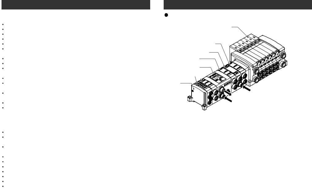
Product Summary
Solenoid valve
Output Block
(for high wattage load)
Power Block
Output Block
(for low wattage load)
SI Unit applicable to
EtherNet/IP
Input Block 
End Plate
Power supply for Output Block (for high wattage load) 24VDC
Connecting to bus at upper level (EtherNet/IP)
Power supply for output/input and control 24VDC
This system realizes reduced wiring between the input and output equipment by connecting to EtherNet/IP. EtherNet/IP and the input and output equipment communicates through the SI Unit.
Up to 32 Inputs can be connected to the SI Unit using Input Blocks.
Up to 32 Outputs Note) from combined EX9 Output Blocks and Valve manifolds can be connected to the SI Unit.
Note) The maximum output point is 24 when the Power Block is connected.
4 |
5 |
SI Unit Model Indication Method
EX250 SEN1
 Communication protocol
EN1 EtherNet/IP
Part Names
Tie-rod (2 pcs.)
Accessory
No. |
Part names |
Application |
|
1 |
Communication |
Connect with EtherNet/IP line. Note1) |
|
connector |
|||
|
|
||
|
|
|
|
2 |
Power supply connector |
Supplies power to the solenoid valve, the Output Block, SI |
|
Unit and the Input Block. Note1) |
|||
|
|
||
3 |
Input Block connector |
Connects the Input Block. |
|
|
|
|
|
4 |
Output Block connector |
Connects the solenoid valve, Output Block and etc. |
|
|
|
|
|
5 |
Display |
LED display shows the SI Unit status. Note2) |
|
6 |
Switch protective cover |
Display the power supply status and communication |
|
status with PLC. Note2) |
|||
|
|
||
7 |
Ground terminal |
Used for grounding. |
|
|
|
|
|
8 |
MAC address |
A unique MAC address of 12 hexadecimal number digits to |
|
each SI Unit. |
|||
|
|
||
|
|
|
Note1 : For wiring method, refer to subsection "Wiring" (page 12) in this manual.
Note2 : For display and setting method, refer to subsection "Display/Setting" (page 15) in this manual.
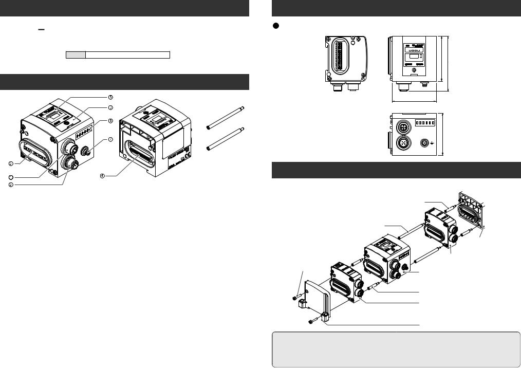
Dimensions ( unit : mm )
|
SOL PWR MS NS |
|
1 |
64.4 |
78.9 |
0 |
SETTINGS
63
- - - - -
BUS
59.8
PWR
Mounting/Installation
How to assemble / disassemble units.
NOTE
Hold the SI Unit and the Input / Output Block in order to have no clearance between them while tightening the bolt.
Be sure to tighten bolt by specified tightening torque. (Tightening torque : 0.6N
6 |
7 |

Mounting/Installation (continued )
 Layout of the Input Block
 Position the Input Block on the left side of the SI Unit.
 Layout of the EX9 series Output Block / Power Block
Position the Output Block / Power Block on the right side of the SI Unit and between the SI Unit and solenoid valve or End Plate R (on the Output Block side).
1) Output Block for high wattage load
The Output Block for high wattage load cannot be used independently. Be sure to combine with the Power Block for use.
|
|
For high |
|
|
Power |
For high |
|||||||||||
SI Unit |
|
wattage load |
SI Unit |
|
Block |
wattage load |
|||||||||||
|
EX9-OEP1 |
EX9-PE1 EX9-OEP1 |
|||||||||||||||
|
|
|
|||||||||||||||
|
|
|
|
|
|
|
|
|
|
|
|
|
|
|
|
|
|
|
|
|
|
|
|
|
|
|
|
|
|
|
|
|
|
|
|
|
|
|
|
|
|
|
|
|
|
|
|
|
|
|
|
|
|
|
|
|
|
|
|
|
|
|
|
|
|
|
|
|
|
|
|
|
|
|
|
|
|
|
|
|
|
|
|
|
|
|
|
|
|
2) Position of Output Block for high wattage load
The Output Block for high wattage load cannot be mounted at the place nearer to the SI Unit than the Power Block. However, that place is acceptable if the Power Block is located between SI Unit and the Output Block for high wattage load.
SI Unit |
|
For high |
|
Power |
|
For high |
SI Unit |
|
|
Power |
|
For high |
|
Power |
|
For high |
||||||||||||||||
wattage load |
|
Block |
wattage load |
|
|
Block |
wattage load |
|
Block |
wattage load |
||||||||||||||||||||||
|
EX9-OEP1 |
EX9-PE1 |
EX9-OEP1 |
|
|
EX9-PE1 |
EX9-OEP1 |
EX9-PE1 |
EX9-OEP1 |
|||||||||||||||||||||||
|
|
|
|
|
|
|
|
|
|
|
|
|
|
|
|
|
|
|
|
|
|
|
|
|
|
|
|
|
|
|
|
|
|
|
|
|
|
|
|
|
|
|
|
|
|
|
|
|
|
|
|
|
|
|
|
|
|
|
|
|
|
|
|
|
|
|
|
|
|
|
|
|
|
|
|
|
|
|
|
|
|
|
|
|
|
|
|
|
|
|
|
|
|
|
|
|
|
|
|
|
|
|
|
|
|
|
|
|
|
|
|
|
|
|
|
|
|
|
|
|
|
|
|
|
|
|
|
|
|
|
|
|
|
|
|
|
|
|
|
|
|
|
|
|
|
|
|
|
|
|
|
|
|
|
|
|
|
|
|
|
|
|
|
|
3) Output Block for low wattage load
The Output Block for low wattage load cannot be mounted at the right side of the Power Block. Mount to the place nearer to the SI Unit than the Power Block.
|
For low |
Power |
For low |
SI Unit |
wattage load |
Block |
wattage load |
|
EX9-OET1 |
EX9-PE1 |
EX9-OET1 |
POWER
PWR
PWR
 Position of End Plate
SI Unit |
For low wattage load |
||||
|
EX9-OET1 |
||||
|
|
||||
|
|
|
|
|
|
|
|
|
|
|
|
|
|
|
|
|
|
 Be sure to connect the End Plate (on the Input Block side) at the left end of the manifold.
When the valve is not connected, be sure to connect the End Plate R (on the Output Block side) at the right end of the manifold.
The number of |
The number of |
|
|
Input Blocks |
Output Blocks |
|
|
SOL PWR MS NS |
|
|
|
1 |
0 |
0 |
|
0 |
66 |
||
0 |
|
|
|
SETTINGS |
|
|
|
1 |
1 |
1 |
|
EX250 |
|
|
|
|
|
|
|
|
|
|
|
|
Mounting hole for 4-M4 |
|
|
|
|
|
|
|
L = 21 x m + 93 |
|
|
Thickness : 13.2 |
|
||
|
|
* The number of Input Blocks + The number of Output Blocks + The number of Power Blocks : m |
|
|
|||||||
L |
m |
1 |
2 |
3 |
4 |
5 |
6 |
7 |
8 |
9 |
10 |
|
L |
114 |
135 |
156 |
177 |
198 |
219 |
240 |
261 |
282 |
303 |
[mm]
*Each dimension shows the unit without solenoid valves connected and with an End Plate R (on the Output Block side) connected. Standard settings of L dimensions are with 10 or less m blocks. Ask SMC sales for the setting with over 10 blocks mounted.
Refer to the individual specifications for the dimensions when the solenoid valves are connected.
Wiring (power supply, communication, input/output) and piping are all in one direction. Space for wiring and piping is required in that direction.
8 |
9 |
 Loading...