


5000

OmniLink 5000
System 5000
Press Control
AUTO SETUP
MODULE
COLOR DISPLAY
OPERATING MANUAL
LINK ELECTRIC & SAFETY CONTROL COMPANY
444 McNALLY DRIVE, NASHVILLE TN 37211
PH (615)-833-4168 FAX (615)-834-1984

April 17, 2000 Man ual Versio n 1.0
i
Table of Contents
Section 1 Introduction .......................................................... 1.1
Section 1.1 Counterbalance Control .............................................. 1.1
Section 1.2 Cushion Control .................................................... 1.1
Section 1.3 Shut Height Control ................................................. 1.2
Section 1.4 Hydraulic Overload Control .......................................... 1.2
Section 2 Parameter Entry and Access Control ....................................... 2.1
Section 2.1 Parameter Entry .................................................... 2.1
Section 2.1.1 Numeric Entries ................................................. 2.1
Section 2.1.2 Text Entry ..................................................... 2.1
Section 2.2 Access Control ..................................................... 2.3
Section 2.2.1 Key Only Mode .................................................. 2.3
Section 2.2.2 Key or Password Mode ............................................ 2.3
Section 2.2.3 Password Only Mode ............................................. 2.4
Section 2.2.4 Key and Password Mode .......................................... 2.4
Section 2.2.5 Restricted Items ................................................. 2.4
Section 2.2.6 Access Control Operation .......................................... 2.4
Section 2.2.6.1 RUN/PROG Key Switch Operation .............................. 2.4
Section 2.2.6.2 Password System Operation ................................... 2.5
Section 3. Installation ........................................................... 3.1
Section 3.1 Auto-Setup Module Installation ........................................ 3.1
Section 3.2 Valve Systems ..................................................... 3.2
Section 3.3 Counterbalance Control Installation .................................... 3.3
Section 3.3.1 Counterbalance Pressure Transducer Mounting ........................ 3.5
Section 3.3.2 Counterbalance Air Valve System Mounting .......................... 3.6
Section 3.3.3 Counterbalance System Wiring ..................................... 3.6
Section 3.4 Cushion System Installation .......................................... 3.6
Section 3.4.1 Cushion Pressure Transducer Mounting .............................. 3.7
Section 3.4.2 Cushion Air Valve System Mounting ................................ 3.7
Section 3.4.3 Cushion System Wiring ........................................... 3.7
Section 3.5 Hydraulic Overload System Installation ................................. 3.8
Section 3.6 Slide Adjust System Installation ....................................... 3.8
Section 3.6.1 Rotary Transducer Mounting ....................................... 3.8
Section 3.6.2 Rotary Slide Adjust Wiring ........................................ 3.9
Section 3.6.3 Linear Transducer Mounting ....................................... 3.9
Section 3.6.4 Linear Transducer Slide Adjust Wiring .............................. 3.10

April 17, 2000 Man ual Versio n 1.0
ii
Section 4. Configuration ......................................................... 4.1
Section 4.1 Setting up the OmniLink 5000 for the Auto-Setup Module .................. 4.1
Section 4.2 Configuring the Auto-Setup board ........................................ 4.2
Section 4.2.1 Configuring Counterbalance, Cushion, and Hydraulic Overload Modules ... 4.2
Section 4.2.2 Configuring Slide Adjust Modules .................................. 4.7
Section 4.2.2.1 Calibrating Linear Slide Adjust Systems ....................... 4.10
Section 4.2.2.2 Calibrating Rotary Slide Adjust Systems ...................... 4.11
Section 5 Operation ............................................................ 5.1
Section 5.1 Slide Adjust Operation ............................................... 5.3
Section 5.1.1 Slide On, Manual, and Off Settings .................................. 5.4
Section 5.1.2 Automatic Slide Movement ........................................ 5.4
Section 5.1.3 Manual Slide Movement .......................................... 5.6
Section 5.1.4 Slide Fault and Status ............................................ 5.6
Section 5.2 Air System (Counterbalance, Cushion, and Hydraulic Overload) Operation ..... 5.6
Section 5.2.1 Air System On, Manual, and Off Settings ............................. 5.7
Section 5.2.2 Pressure and Force Setpoints ....................................... 5.7
Section 5.2.3 Air System Fault and Status ........................................ 5.8
Section 5.3 Job Storage and Recall Issues ......................................... 5.8
Section 6 Diagnostics - Fault and Status Messages .................................... 6.1
Section 6.1 Main Module Messages .............................................. 6.1
Section 6.2 Counterbalance, Cushion, and Hydraulic Overload “Fault” Messages .......... 6.1
Section 6.3 Counterbalance, Cushion and Hydraulic Overload “Status” Messages .......... 6.2
Section 6.4 Slide Adjust “Fault” Messages ........................................ 6.3
Section 6.5 Slide Adjust “Status” Messages ........................................ 6.4
Appendix A Configuration Examples ................................................A.1
Section A.1 Example Counterbalance Configuration .................................A.1
Section A.2 Example Cushion Configuration .......................................A.2
Section A.3 Example Hydraulic Overload Configuration ..............................A.3
Section A.4 Example Linear Slide Adjust Configuration ..............................A.5
Section A.5 Example Rotary Slide Adjust Configuration ..............................A.7
Appendix B Typical Wiring Diagrams ...............................................B.1
Appendix C Installation Of OmniLink 5000 Firmware ...................................C.1
Appendix D Lockout Procedure For Air Controlled Systems ..............................D.1
Section D.1 General Lockout Considerations .......................................D.1
Section D.2 Valve Type “A” Lockout Procedure ....................................D.1
Section D.3 Valve Type “B” Lockout Procedure ....................................D.2
Section D.4 Valve Type “C” Lockout Procedure ....................................D.2
Appendix E Configuration Sheets ................................................... E.1
Section E.1 Air System Calibration Sheets .........................................E.1
Section E.2 Shut height Calibration Sheets ........................................... E.3

April 17, 2000 Man ual Versio n 1.0
iii
Appendix F Specifications ......................................................... F.1
Section F.1 5000-10A Pressure Control Board ...................................... F.1
Section F.2 5000-10B Linear Shut Height Control Board ............................. F.1
Section F.3 5000-10C Rotary Shut Height Control Board ............................. F.1

April 17, 2000 Man ual Versio n 1.0
iv

April 17, 2000 Man ual Versio n 1.0
1.1
Section 1 Introduction
The 5000-10 Auto-Setup Module (ASM) allows the OmniLink 5000 Press and Automation control to
set up press shut height, counterbalance air pressure, cushion air pressures, and hydraulic overload
pressure settings automatically when jobs are recalled from memory. It consists of a base 5000-10
microprocessor board that installs in the OmniLink extended card rack, and additional modules that may
be mounted on the base board to provide pressure or shut height adjustment functions. When one slide
adjust is provided , up to four air systems and a hydraulic overload can be adjusted. For double action or
banjo presses with two slide adjust systems, up to two air systems and a hydraulic overload can be
adjusted.
Section 1.1 Counterbalance Control
The proper setup of the air counterbalance system in a press is often thought of as a relatively
unimportant detail. In fact, the counterbalance performs a very critical function. By countering the
weight of the slide and its associated tooling a properly adjusted counterbalance:
Takes up bearing clearances before the die closes at the bottom of the stroke, reducing bearing load
and impact.
Helps reduce gear tooth impact in geared machines by maintaining drive edge gear tooth contact in
the press downstroke.
Decreases the downstroke stopping time of the press since less load is seen by the brake in the
downstroke.
Enhances safety by reducing the possibility that the slide will free fall, if the brake is released and
the clutch is not engaged.
Causes less total energy to be used by the press.
Increases drive motor life by reducing peak motor currents.
None of the foregoing advantages will be realized if the counterbalance pressure is set too low. But a
counterbalance pressure that is set too high is also detrimental to the press, causing excessive clutch
wear and loss of flywheel energy in the downstroke before material is contacted by the dies.
By setting the pressure automatically when a job is recalled, the OmniLink 5000 assures that the
pressure is correct for the tooling used. This not only reduces machine maintenance, but increases safety
and speeds up job setup tremendously. In addition, the Auto-Setup module sets the correct pressure for
each die, rather than an approximate pressure for a range of die weights from tables provided with
manually adjustable counterbalance systems.
Section 1.2 Cushion Control
Quick die change is becoming increasingly important to maintaining a competitive edge. By controlling
up to four cushions automatically, the OmniLink 5000 can shorten die change and assure a correct setup
in the least amount of time.

April 17, 2000 Man ual Versio n 1.0
1.2
Section 1.3 Shut Height Control
When a linear or rotary shut height control module is provided, the OmniLink 5000 can provide
accurate, repeatable shut height adjustment on presses that are in reasonable mechanical condition,
enhancing parts quality and reducing setup time. This system uses the existing slide motor starter.
Section 1.4 Hydraulic Overload Control
Most presses use a hydraulic overload system in which an air pressure sets up a much greater hydraulic
pressure to control the trip point (tonnage) at which the overload cylinder collapses. On these presses
the OmniLink 5000 can control the trip point to not only protect the machine, but also protect the tooling
on each job.

April 17, 2000 Man ual Versio n 1.0
2.1
Section 2 Parameter Entry and Access Control
Section 2.1 Parameter Entry
Throughout the OmniLink control, a fairly standard form of data entry is employed. When data entry is
allowed, an “editing cursor” will appear on the screen. This cursor can typically be moved from
parameter to parameter on the screen with the up, down, left, and right arrow keys. The topmost softkey
is used to select the parameter for editing and can change description depending on the parameter
selected.
Section 2.1.1 Numeric Entries
Assuming access has been achieved by one of the means listed in the following sections, to change a
numeric value:
a) Place the editing cursor on the parameter to be changed by using the up, down, left, and right
arrow keys as appropriate. Note that the editing cursor will only appear on the screen when
editing is allowed. For instance, editing is usually not allowed when the press is running.
b) The topmost softkey will usually say something along the lines of “CHANGE XXXXXX” where
XXXXXX is the name of the value to be changed. It may also simply say “CHANGE
NUMBER.” In any case, hit this softkey to enter numeric input mode. The editing cursor will
change to a rectangle around the parameter to be edited.
c) Use the numeric keypad to input the new number desired for the parameter.
d) Press the ENT key to finish.
Note that moving off the parameter with the arrow keys or hitting the EXIT key will abort the edit and
leave the parameter at the value it had before the editing process began.
Section 2.1.2 Text Entry
For text entry:
a) Place the editing cursor on the text to be changed by using the up, down, left, and right arrow
keys as appropriate. Note that the editing cursor will only appear on the screen when editing is
allowed. For instance, editing is usually not allowed when the press is running.
b) The topmost softkey will usually say something along the lines of “CHANGE XXXXXX” where
XXXXXX is the name of the value to be changed. It may also simply say “CHANGE TEXT” or
“CHANGE DESC.” In any case, hit this softkey to enter text entry mode. The right-hand
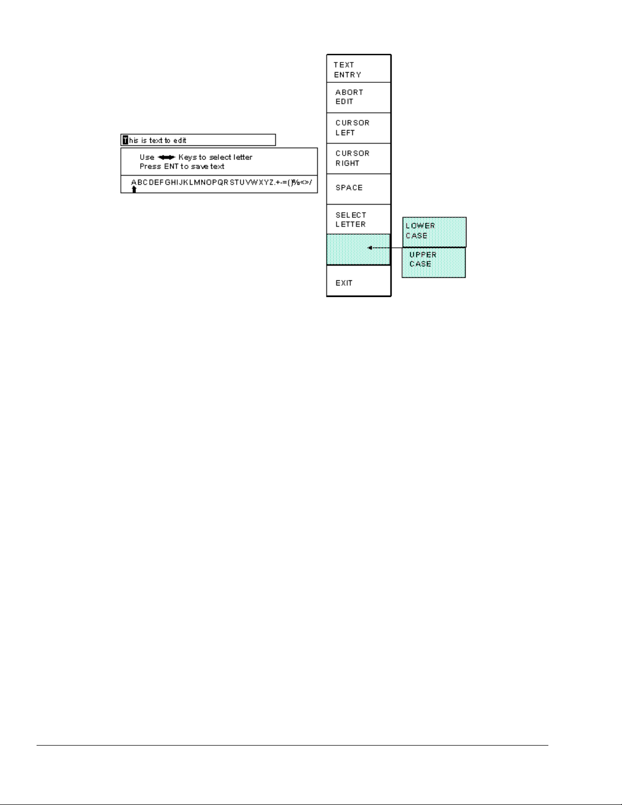
softkeys will change, a letter selection box will appear, and the editing cursor will change to a
rectangle around the text to be edited. Figure 2.1 shows the softkeys and an example text
parameter.
April 17, 2000 Man ual Versio n 1.0
2.2
Figure 2.1: Example Text Entry
c) The fist character of the text is highlighted with the text cursor. The CURSOR LEFT and
CURSOR RIGHT softkeys will move this cursor.
d) Use the left and right arrow keys to point to the letter desired in the letter box next to the text
being edited. This box will just appear above or just below the text to be edited depending on
where it is in the screen. Hit the SELECT LETTER softkey to place that letter at the text cursor.
In the example above, the text cursor is on the “T” in “This” and would be replaced with an “A”.
The text cursor will automatically move to the right when a letter is selected. Note that numerals
can be entered directly with the numeric keypad.
e) The SPACE softkey can be used to enter a space character in the text.
f) The softkey immediately above the EXIT softkey is used to select between uppercase and
lowercase letters.
g) The EXIT or ABORT EDIT softkeys can be used to abort the editing operation. The text will
revert to what it was before the editing operation started.
h) After the text has been changed as desired, press the ENT key to accept the changes.

April 17, 2000 Man ual Versio n 1.0
2.3
Section 2.2 Access Control
The OmniLink control has several parameters or operations that have limited access. In regards to the
auto setup module the ability to perform the actions of resetting faults or changing limits must be
restricted to certain personnel. The OmniLink control provides several means to limit access to these
parameters or operations. These parameters and operations are called restricted items.
The OmniLink control employs combinations of two different means to limit access to restricted items.
These means are the RUN/PROG key switch on the operator terminal and a user password system. The
user password system assigns names and passwords to up to sixteen users. These two means can be
used alone or in combination with each other. When a user employs the proper means to gain access, he
will have the ability to perform the actions and change the parameters which have been designated to his
control.
There are four possible modes of operation for the restricted access system. They are the “Key Only”
mode, the “Key or Password” mode, the “Password Only” mode, and the “Key and Password” mode.
The control can be configured to operate in any one of these four modes.
Section 2.2.1 Key Only Mode
The “Key Only” mode is the least complex of the four modes. This mode employs the RUN/PROG key
as the only means to limit access to restricted items. Any user with the RUN/PROG key can access all
of the restricted items. Without the RUN/PROG key, user access to all of the restricted items is
prohibited.
Although the “Key Only” mode has the advantage of being easy to use, it does have a disadvantage.
This mode cannot give a particular user access to only some of the restricted items. When operating in
this mode, any user with the RUN/PROG key will have access to all of the restricted items.
Section 2.2.2 Key or Password Mode
The key or password mode allows for either of two means to gain access to the restricted items. A user
with RUN/PROG key can access all of the restricted items. A user with the correct password can access
the restricted items that have been designated for that particular user only. The system allows for
passwords to be assigned to sixteen users. Each user can be assigned access to any or all of the restricted
items.
The following is an example of a “Key or Password” mode operation. The RUN/PROG key is given to
the die set-up personnel. A press operator is assigned a user name and password. With the password
the operator can reset auto setup faults. This is the only auto setup related item to which the operator
has access. In order to load a die, the set-up personnel uses the RUN/PROG key to recall a job from job
storage. The set-up personnel will also be able to make changes to auto setup limits. Once the set-up
personnel sets the die and verifies its correct operation, the operator is left to run the die. If an auto setup
fault occurs, the operator can enter the correct password and then reset the fault. However, the operator
cannot change auto setup limits. This will allow the operator to keep running the job and reset faults
that occur. However, if consistent stops occur because an auto setup limit needs changing, the set-up
personnel must be called to change the limit.

April 17, 2000 Man ual Versio n 1.0
2.4
The example above can be taken one additional step if two press operators are given different user
names and different passwords. One operator can be assigned the ability to change auto setup limits in
addition to the ability to reset faults, while the other operator is not assigned the ability to change the
limits.
Section 2.2.3 Password Only Mode
The “Password Only” mode allows for sixteen users. Each user can be assigned access to some or all of
the restricted items. This mode does not use the RUN/PROG key.
The example listed above indicated that setup personnel required access to all restricted items. In the
“Key or Password” mode, the setup personnel used the RUN/PROG key to gain access to all of the
restricted items. In the “Password Only” mode, the setup personnel can still have access to all of the
restricted items, but the system must be configured as such. The setup personnel must be assigned a user
name and password. In addition, all restricted items would be assigned access to the setup personnel.
Section 2.2.4 Key and Password Mode
The “Key and Password” mode requires the user to have the RUN/PROG key, user name, and user
password. Operation is basically the same as the Password only mode, except that in addition to
entering the password the user must switch the RUN/PROG key to the PROG position.
Section 2.2.5 Restricted Items
The following table lists the auto setup module restricted items name and function.
AUTO SETUP MODULE RESTRICTED ITEMS
NAME FUNCTION
Auto Setup Reset Reset Auto Setup Faults
Auto Setup Settings Change Auto Setup Settings (Pressures, Slide Setpoints, etc.)
Section 2.2.6 Access Control Operation
To gain access control the user must use one of two means or a combination of these two means. These
means are the RUN/PROG key or the user password system.
Section 2.2.6.1 RUN/PROG Key Switch Operation
The RUN/PROG key switch is located on the lower right side of the operator terminal. This is a two
position switch. The key is removable in the RUN position only. If the RUN/PROG key switch is
being used as a means to access the restricted items, the switch must be turned to the PROG position.
When the RUN/PROG key switch is switched to the PROG position, the press will Top Stop and
stroking will be prohibited until the switch is returned to the RUN position.
April 17, 2000 Man ual Versio n 1.0
2.5
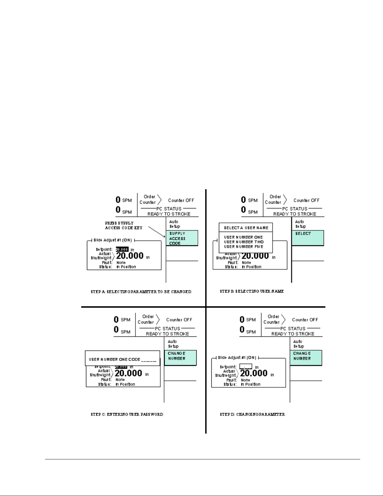
Figure 2.2: Example Password Entry Sequence
When operating in the Key Only mode the key switch is the only means available to access the restricted
items. All restricted items are accessible when the RUN/PROG key switch is switched to the PROG
position.
When operating in the “Key or Password” mode, the key switch is one of the means available to access
the restricted items. All restricted items are accessible when the RUN/PROG key switch is switched to
the PROG position.
When operating in the “Key and Password” mode, the key switch and password must be used to access
the restricted items. In this mode, the user will be granted access only to the restricted items that have
been assigned to him.
Section 2.2.6.2 Password System Operation
Figure 2.2 displays a typical password entry sequence. This example shows the steps necessary to
change a slide adjust setpoint. This is typical for password entry for all restricted items.

April 17, 2000 Man ual Versio n 1.0
2.6
Step A: Select the restricted item. In the example shown in Figure 2.2 the restricted item is Slide
Adjust #1 setpoint. Once the parameter is selected then Softkey # 1, the upper vertical
softkey (Softkey # 1 is highlighted in Figure 2.2) , will display the legend “SELECT”.
Step B: A list of users that have access to this restricted item will appear. In the example shown in
Figure 2.2 only User Number One, User Number Two, and User Number Five have access to
this restricted parameter. The system may have several more users, but the three users listed
on the screen are the only users that have access to change an Auto Setup Setting . The user
must use the arrow keys to position the cursor on his user name. After placing the cursor on
the correct name, the user must press the SELECT softkey. The SELECT softkey must be
pressed even if there is only one user name displayed.
Step C: The display will show the selected user name and request the user password. The user must
enter the correct password and then press the ENT key.
Step D: Upon entry of the correct password, the user will be allowed access to the restricted item. In
the example shown in Figure 2.2, the user will have access to change the Slide Adjust #1
setpoint.
After performing the steps listed above, the user will be logged in to the password system. The user will
have access to all restricted items that have been designated for his access. This access will remain until
the user performs a log out or until the user is automatically logged out.
The user can log out by using the ACC key. This key will directly switch the display to the Quick
Access screen. The “LOGOUT” soft key legend will appear along the bottom of the screen. If the
operator presses this key, he will log out. He will no longer have access to the restricted items, unless he
repeats steps A through D.
In addition to the manual log out, the system contains an automatic logout. The intent of automatic log
out is to reduce the possibility of users other than the intended user having access to restricted items. If
there were no provisions for automatic log out and a user forgot to manually log out, all restricted items
to which the user had been designated for access would be available from the log in time until power
was removed from the OmniLink control. This presents the possibility of users other than the intended
user having access to restricted items. Automatic log out is based upon both time and press strokes.
During system configuration automatic Access Timeout parameters are entered. An automatic access
timeout time and automatic access timeout strokes are entered. The time entered is the amount of time
after the last key stroke that will be allowed before the system will automatically log out the user. For
example, if the automatic access timeout is set to 60 seconds, the user will be logged out 60 seconds
after the last key stroke. If the user presses a key before the 60 seconds have elapsed, a new 60 second
cycle will be started. The number of strokes that are entered is the number of press strokes after the last
key stroke that will be allowed before the system automatically logs out the user. For example, if the
automatic timeout is set to 10 strokes, the user will be logged out when the press completes ten strokes
after the last key stroke. If the user presses a key before 10 strokes have been completed, a new 10
stroke cycle will be started.
April 17, 2000 Man ual Versio n 1.0
3.1
NOTE: NEVER remove or install any card in the OmniLink 5000 when the power to the
control is on. Doing so can damage the control, the card, or both!
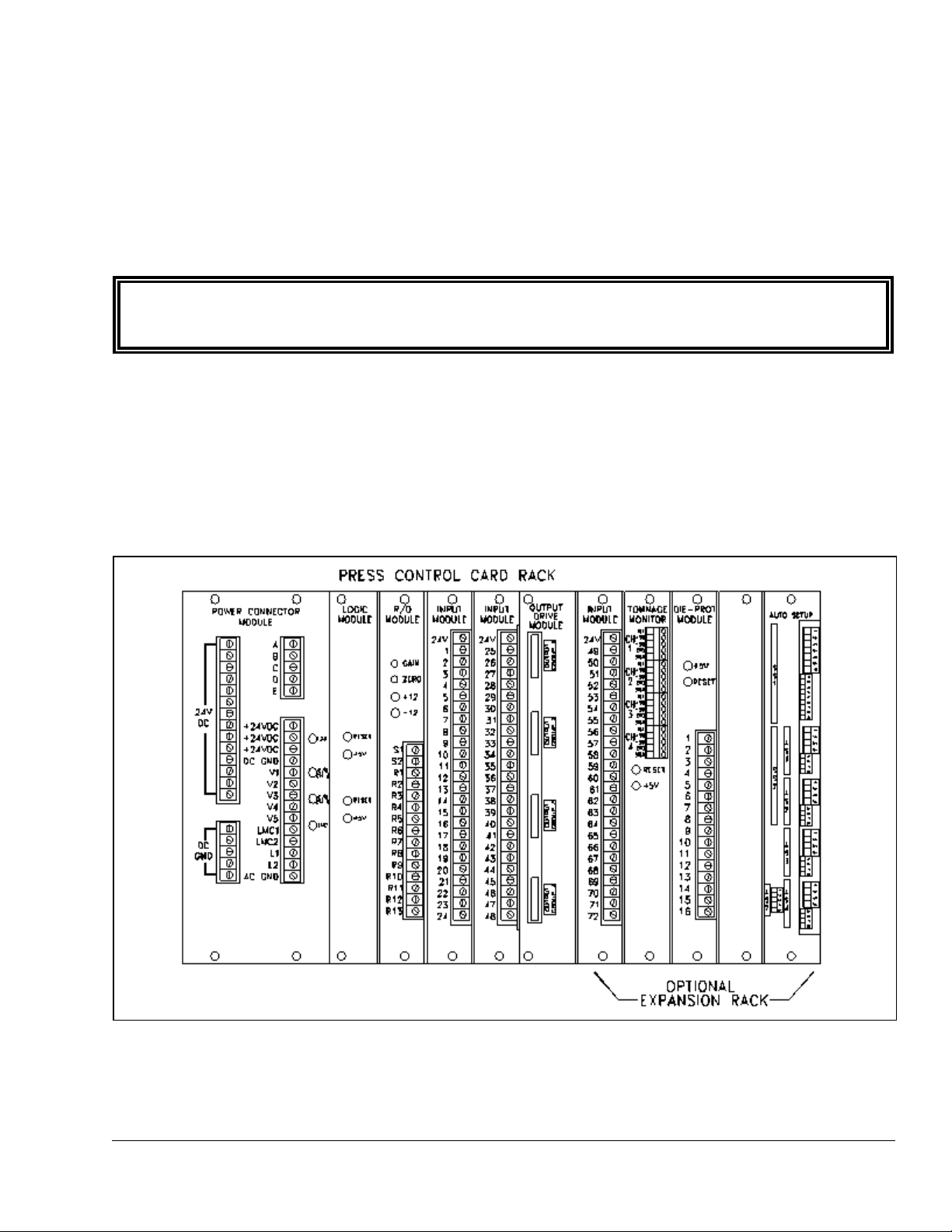
Figure 3.1: OmniLink 5000 Extended Card Rack
Section 3. Installation
Section 3.1 Auto-Setup Module Installation
The 5000-10 Auto-Setup Module (ASM) installs in the OmniLink 5000 extended card rack. Figure 3.1
shows the location of the ASM in the last slot of the extended card rack. To remove the module, loosen
the knurled screws at the top and bottom of the board and use them to pull the board straight out of the
rack. To install, start the module in the card guide slots on the rack, push straight into the rack to firmly
seat the module, and tighten the knurled screws.
The face plate of the ASM is partitioned with labels such as “SS1", “AS1", etc. These labels represent
the type of module that can be installed on the card at that location. “SS1" and “SS2" can have slide
adjust modules installed. “AS1" through “AS4" can have air adjust modules (counterbalance and
cushion use the same control module) installed. Slide adjust cards are twice the width of air adjust
cards. Note that SS2 overlaps with AS1 and AS2 to allow a second slide adjust card to be installed in a
double action press at the expense of two air slots. “AS7" is used for hydraulic overload control and is
built in to the base card.
Each module is held on to the base card by four #6-32 screws. If not already assembled, install each
module on the base card putting slide adjust cards in SS1 or SS2 and air adjust cards in AS1, AS2, AS3,

April 17, 2000 Man ual Versio n 1.0
3.2
or AS4. The plug in terminals on the modules should stick out of the faceplate of the base card.
April 17, 2000 Man ual Versio n 1.0
3.3
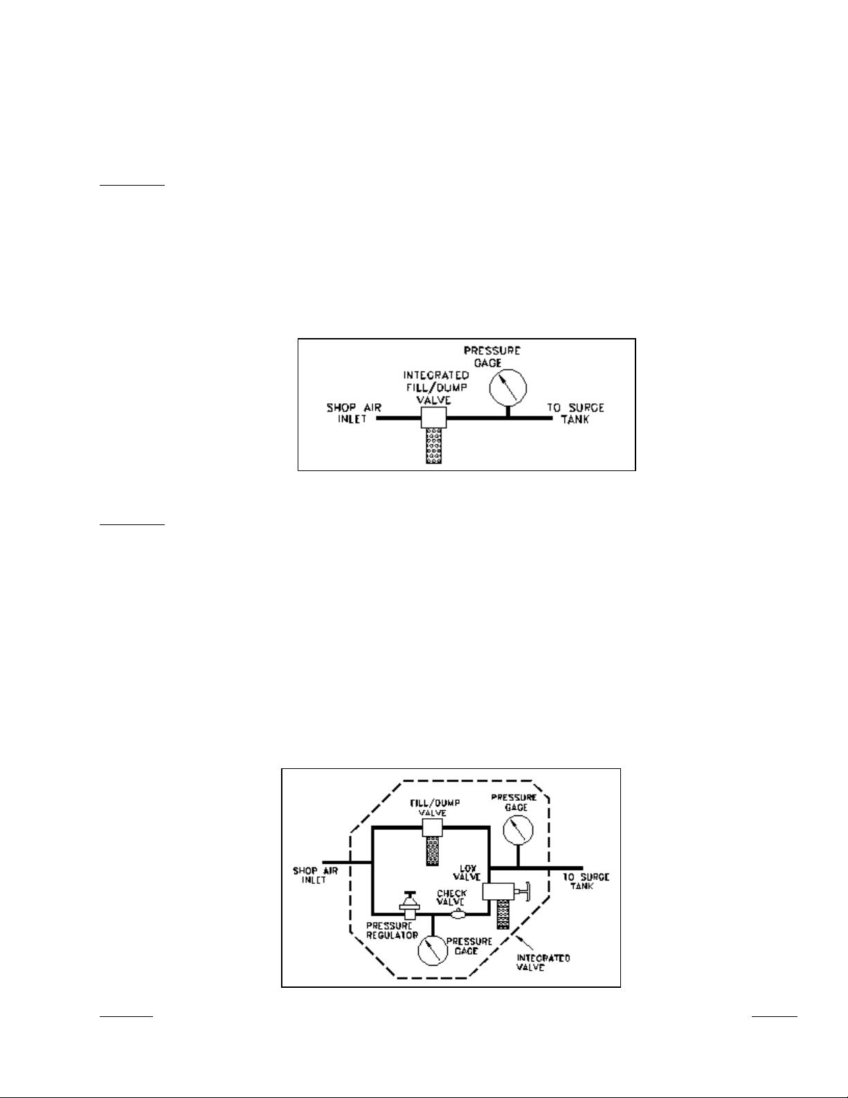
Figure 3.2: Type “A” Valve Configuration
Figure 3.3: Type “B” Valve Configuration
Section 3.2 Valve Systems
Counterbalance and cushion systems are very similar in the way they are controlled. Three basic
integrated valve configurations are available from Link to be used with the OmniLink 5000 ASM. For
clarity in the following sections, these valve configurations are defined here.
Type “A”
An integrated Fill/Dump Valve as shown in Figure 3.2. This valve has the advantage of
simple straight through piping with all pilot pressures run internally and is easily
mounted. It may be used for air cushion and air counterbalance control. This is the least
expensive of the three valves. Leaks in cushion and counterbalance systems will cause
loss of pressure in these systems when either control power is off or supply pressure is
absent. However, the control must be turned back on and pressure re-established before
the press will stroke.
Type “B”
An integrated Fill/Dump valve with a manual regulator, check valve, and LOX valve in
parallel as shown in Figure 3.3 for cushion, but not counterbalance, adjustment. This
valve adds a parallel manual regulator system to the Type “A” valve, which may be set
to prevent the air pressure in the cushion from going below a minimum value set by the
manual regulator (as long as there is shop air pressure). This prevents cushion drift down
when control power is off with its associated lost die pins below the press bolster and lost
time while they are recovered. This valve also allows the cushions to be adjusted using
the manual regulator path if the automatic system fails, allowing the press to be operated
until the automatic system is restored. When the automatic system is on, the manual
regulator on this valve system must not be set higher than the lowest pressure that the
automatic system is to provide, because the automatic valves will try to dump while the
manual regulator fills if the automatic setpoint is lower than the manual regulator
pressure.
April 17, 2000 Man ual Versio n 1.0
3.4
Figure 3.4: Type “C” Valve Configuration
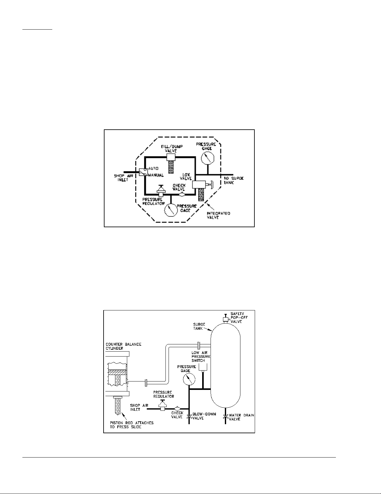
Figure 3.5: Typical Counterbalance System
Type “C” An integrated Fill/Dump valve with a manual regulator, check valve, and LOX valve, and
a four-way valve that selects whether the pressure is set by the automatic system or the
manual regulator as shown in Figure 3.4 for cushion and counterbalance adjustment.
Unlike the type “B” valve, the manual regulator can be set to any allowable pressure
without interfering with automatic pressure adjustment- it does not have to be a minimum
pressure. This system is ideal for press counterbalance systems as the manual regulator
can be set to balance the heaviest die used on the press. When the OmniLink 5000
control is powered off, the valve automatically reverts to at least the pressure set by the
manual regulator. If there is an air leak in the counterbalance system, the manual
regulator keeps the system charged to support the weight of the die.
Section 3.3 Counterbalance Control Installation
The automatic counterbalance control system consists of an air control module mounted on the ASM, a
control valve (or valves) , and a pressure transducer. The typical manually controlled press
counterbalance system looks something like Figure 3.5.
April 17, 2000 Man ual Versio n 1.0
3.5
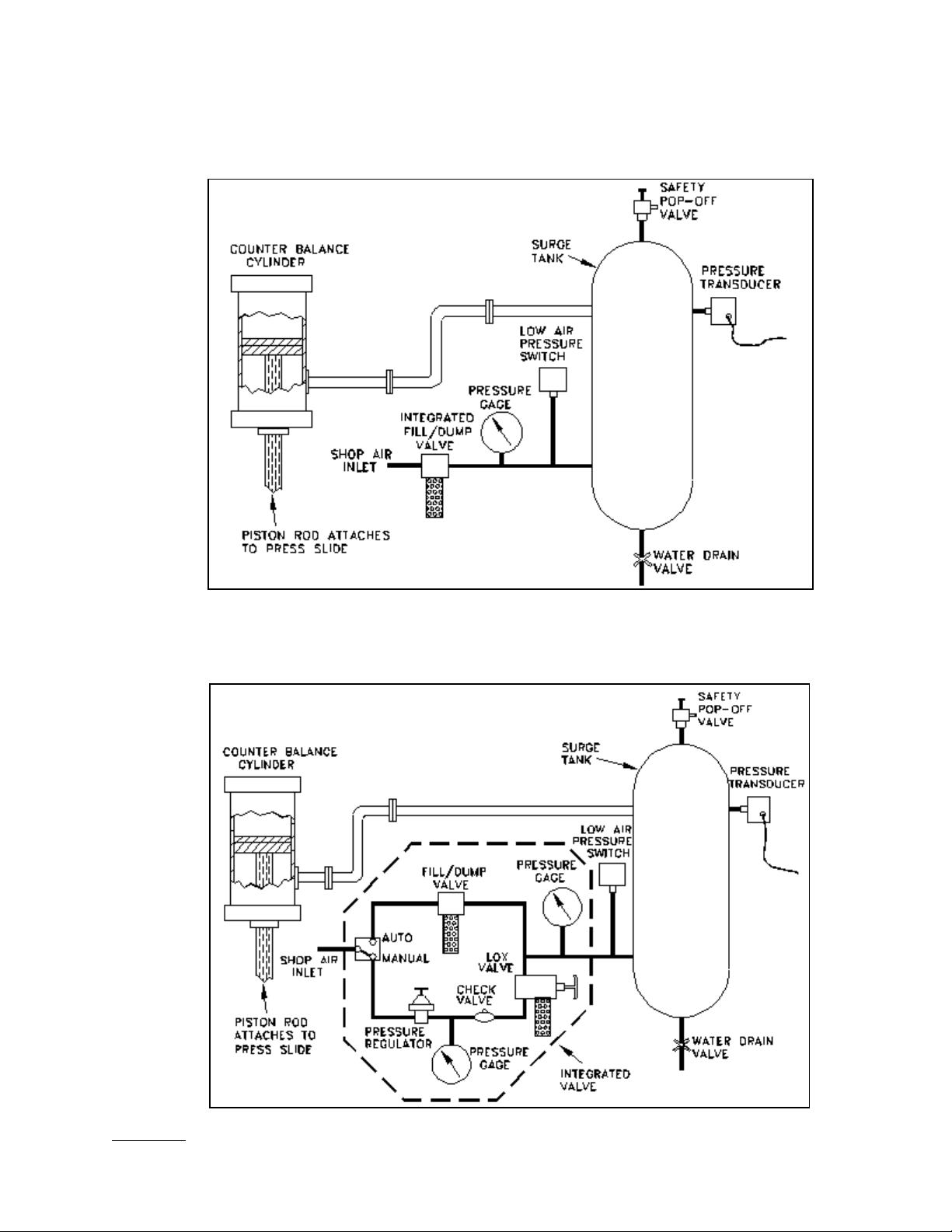
Figure 3.6: Auto-Counterbalance with Type “A” Integrated Valve.
Figure 3.7: Auto-Counterbalance with Type “C” Integrated Valve.
For automatic control, the pressure regulator and check valve are replaced with an air valve system.
Figures 3.6 and 3.7 illustrate systems using the Type “A” and Type “C” valves described in section 3.2.
In all cases a pressure transducer is used to monitor the air pressure.
April 17, 2000 Man ual Versio n 1.0
3.6
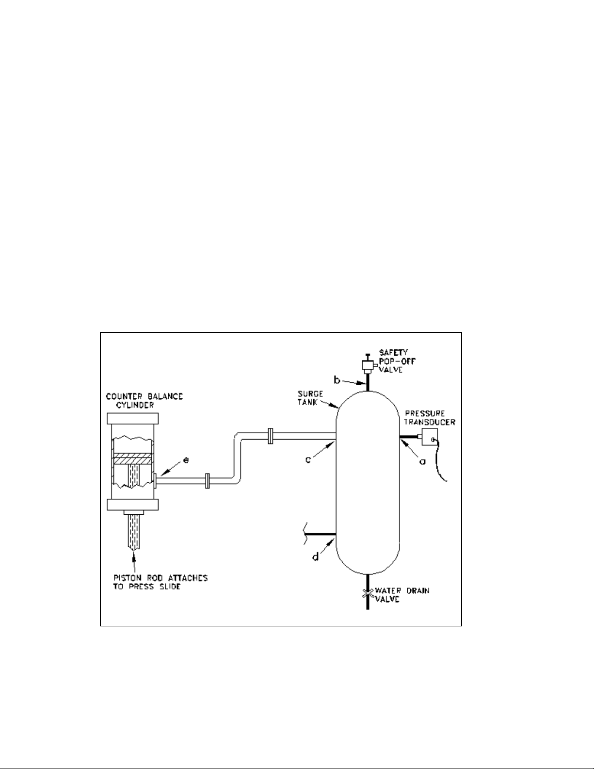
Figure 3.8: Acceptable Locations for Mounting Counterbalance Pressure
Transducer.
Section 3.3.1 Counterbalance Pressure Transducer Mounting
The system uses an automatic method of control in which the fill valve or dump valve is energized to
raise or lower the pressure of the system and a pressure transducer is used to “tell” the ASM what
pressure is in the system. The pressure transducer is constantly monitored to verify that the system is at
the proper pressure. When filling or dumping air into or out of the counterbalance, the transducer tells
the system when to stop. Because air pressure drops occur across air lines when filling or dumping,
proper placement of the pressure transducer is very important for correct operation of the system.
Possible pressure transducer mounting locations from best to worst are (refer to Figure 3.8):
a) A spare port on the counterbalance surge tank.
b) The same port that the safety pop-off valve is mounted on if it has its own port on the surge tank.
c) Right at the outlet on the surge tank that goes to the counterbalance cylinder.
d) Right at the inlet on the surge tank from the Fill/Dump valves.
e) If there is no surge tank the pressure transducer should be mounted right at the inlet on the
counterbalance cylinder.
April 17, 2000 Man ual Versio n 1.0
3.7
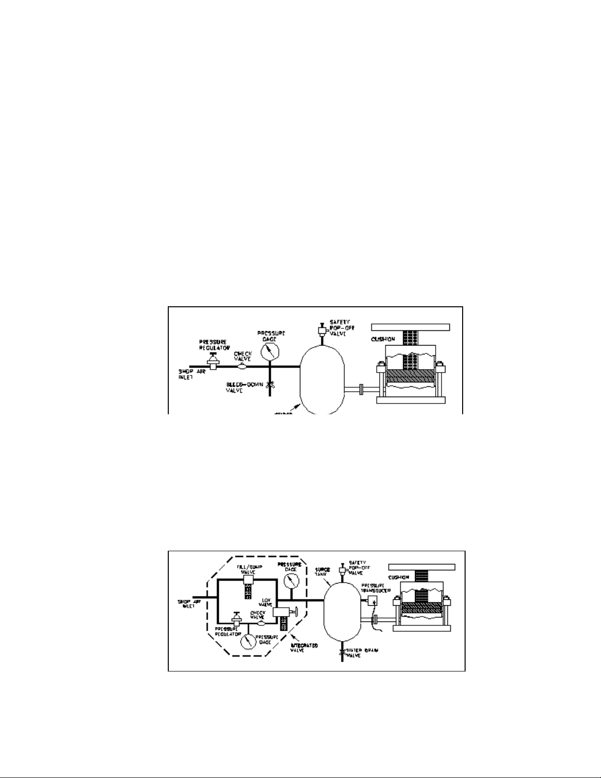
Figure 3.9: Typical Standard Cushion System
Figure 3.10: Cushion System with Type “B” Integrated
Valve.
Section 3.3.2 Counterbalance Air Valve System Mounting
The mounting location of the valve system is not critical. Consideration should be given, however, to
ease of maintenance, plumbing, and wiring when choosing the mounting location. Also note that
sometimes the check valve in the original system may be up at the surge tank itself. The check valve in
the original system must be removed for the automatic system to work properly.
Section 3.3.3 Counterbalance System Wiring
Refer to Appendix B, Figure B.1, for typical wiring of the counterbalance valve and pressure transducer.
Note that the auto-select connection is used only for a type “C” valve. For type “A” valves, the auto-
select connection from pin 2 of the counterbalance module is not required. If you order an OmniLink
control with a counterbalance adjust system, then a wiring diagram will be provided as part of the
documentation package.
Section 3.4 Cushion System Installation
The typical manually adjustable press cushion system looks something like Figure 3.9.
For automatic control, the pressure regulator and check valve are replaced with an air valve system.
Figure 3.10 shows a system using a Type “B” valve as described in section 3.2. Type “A” and “C”
valves may also be used. A pressure transducer is used to monitor the air pressure.
April 17, 2000 Man ual Versio n 1.0
3.8
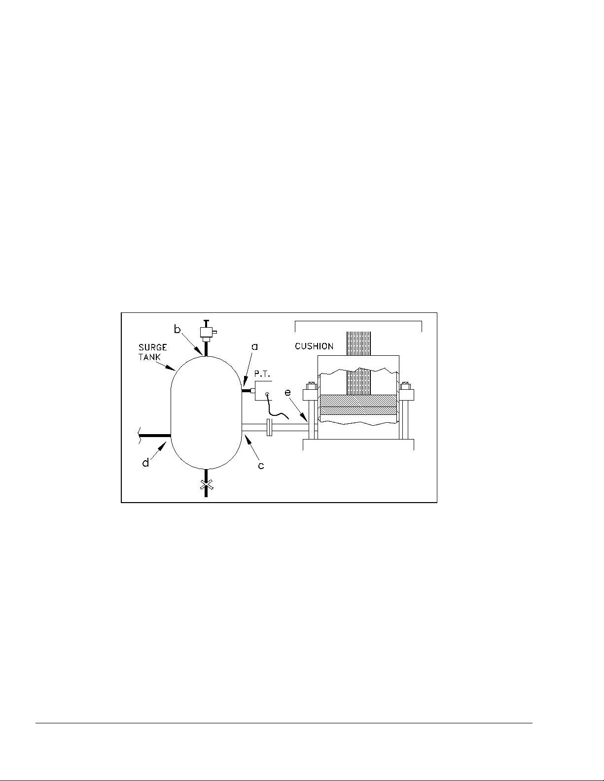
Figure 3.11: Acceptable Locations for Mounting Cushion
Pressure Transducer.
Section 3.4.1 Cushion Pressure Transducer Mounting
The system uses a method of control in which the fill valve or dump valve is energized to raise or lower
the pressure of the system. The pressure transducer tells the system when it has reached the proper
pressure. Because air pressure drops occur across air lines when filling or dumping, proper placement of
the pressure transducer is very important for correct operation of the system. Possible pressure
transducer mounting locations from best to worst are (refer to Figure 3.11):
a) A spare port on the cushion surge tank.
b) The same port that the safety pop-off valve is mounted on if it has its own port on the surge tank.
c) Right at the outlet on the surge tank that goes to the cushion.
d) Right at the inlet on the surge tank from the Fill/Dump valves.
e) If there is no surge tank the pressure transducer should be mounted right at the inlet on the
cushion.
Section 3.4.2 Cushion Air Valve System Mounting
The mounting location of the cushion air valve system is not critical. Consideration should be given,
however, to ease of maintenance, plumbing, and wiring when choosing the mounting location. Also
note that sometimes the check valve in the original system may be up at the surge tank itself. The check
valve must be removed for the automatic system to work.
Section 3.4.3 Cushion System Wiring
Refer to Appendix B, Figure B.2, for typical wiring of the cushion valve and pressure transducer. Note
that the auto-select connection is only connected if a type “C” integrated valve is used. For type “A”
and “B” valves, the auto-select connection from pin 2 of the cushion module is not required. If your

April 17, 2000 Man ual Versio n 1.0
3.9
control came configured for a cushion adjust system, then a wiring diagram should have been provided
as part of the documentation package.
Section 3.5 Hydraulic Overload System Installation
Some press hydraulic overload systems use an air pressure to set up a much greater hydraulic pressure
through an air pump to control the trip point (tonnage) at which the hydraulic overload cylinder will
dump. On these presses the auto-setup card can use an E/P valve (also known as a servo valve) to
actually set the trip point for the hydraulic overload.
These systems vary widely, and it will be necessary for Link to obtain prints of the press hydraulic
overload system in order to determine where to mount control components. If your control came
configured for a hydraulic overload adjust system, then a wiring diagram should have been provided as
part of the documentation package.
Section 3.6 Slide Adjust System Installation
Standard slide adjust systems that set shut height on presses vary widely depending on manufacturer and
age. In general, slide adjust systems are either manually turned by wrenches or levers, or use electric or
air motors to adjust the shut height. The OmniLink automatic slide adjust system can only be used on
presses with motorized slide adjust. Slide adjust motor(s) must be wired to the automatic shut height
adjust module(s) in the OmniLink extended card rack. In addition, either a linear magnetostrictive or a
rotary resolver based transducer must be mounted in such a way as to detect slide adjust position and
wired to the automatic shut height module. Rotary transducers may be used when shafts that turn when
shut height is adjusted are accessible such as a shaft that drives a mechanical shut height indicator.
Linear transducers must be used if no rotating shaft is accessible, but the linear transducer can only be
used on presses with barrel screw type adjustment mechanisms.
Section 3.6.1 Rotary Transducer Mounting
The Link software supports two different types of rotary transducers for the slide adjust system. Both
are based on dual resolvers to provide an absolute position indication. Resolvers are a tough, accurate
rotary position sensor. By using two resolvers mounted in an enclosure with one resolver geared down
relative to the other, a multi-turn resolver (typically around 100 turns) is created.
As mentioned earlier, just about every slide adjust system is different. Some point must be found that
rotates when the slide is adjusted. Some obvious points are the slide adjust motor shaft and the shaft that
drives a dial counter (if present) that indicates slide position. Depending on the press, there may be
other points that can be used. The resolver should be tied in to one of these points - and may need to be
geared up or down. Requirements are:
a) As much as possible, the resolver should be mounted where it will not be submerged in oil,
grease, or other contaminants.
b) The total slide travel from maximum shut height to minimum shut height must not exceed the
number of turns of the resolver. If , for example, a 100 turn resolver is used, the total slide travel
from maximum to minimum must not result in more than 100 turns at the resolver.

April 17, 2000 Man ual Versio n 1.0
3.10
NOTE: The cable should remain unbroken except for the connector in this junction box to
keep the shield integrity - do not splice the cable!
c) The slide should travel no more than 1 inch per turn of the resolver.
d) The cable from the resolver to the OmniLink 5000 should not be run with any high voltage
wiring (i.e. 120/240 VAC). In fact, this cable should be run in its own shielded conduit.
It is not necessary to know the exact gear ratio of slide travel to resolver turns - only that conditions “b”
and “c” are met. The resolver may rotate in either direction relative to slide travel (i.e. the resolver may
rotate clockwise or counter-clockwise as the slide goes down).
Section 3.6.2 Rotary Slide Adjust Wiring
A cable must go from the dual resolver mounted on the slide to the auto-setup board in the OmniLink
5000 extended card rack. Since the slide goes up and down relative to the machine, some means of
stress relief must be used on the cable between the slide and the machine frame. The recommended
method is to use a helical cable (same principle as a telephone handset cord) from the resolver to a
junction box on the bottom of the crown. This lets the wire run in a “spring” pattern to help it resist
breaking. Appendix B, Figure B.3 shows a conceptual view of this type of resolver mounting. The
junction box should be grounded to the machine to help shield the connections inside.
Slide adjust motor starters with and without auxiliary contactors are supported. Solenoid air valves for
air motors are also supported. Refer to Appendix B for typical wiring diagrams. Figures B.4 and B.5
show the wiring for two supported dual resolvers. Figures B.9 and B.10 show the wiring of slide adjust
motor starters with and without auxiliary contactors. Figure B.11 shows the wiring of a slide adjust air
motor. If an OmniLink 5000 control is ordered with a slide adjust system, then a wiring diagram will be
provided as part of the documentation package.
Section 3.6.3 Linear Transducer Mounting
Linear shut height control makes use of linear magnetostrictive transducers. These transducers have a
head that contains the electronics and a guide tube from 6" to 48" in length depending on the application.
The guide tube is mounted to pass through (without touching) a separately mounted annular (doughnut
shaped) magnet. The electronics sense the magnet location as the magnet moves up or down the guide
tube when the slide is adjusted to provide shut height distance to the OmniLink 5000 control.
To install the linear transducer, there must be some point on the slide assembly that moves up and down
with respect to a fixed point on the slide assembly when the shut height is changed. The transducer
should be mounted to one point and the magnet to the other with strong, rigid, brackets. The particulars
of mounting a linear transducer may vary greatly from press to press but keep in mind the following
points:
a) Make sure there is adequate clearance from the transducer to the crown or other possible
interference points of the press. A common mistake is mounting the transducer with the slide
lowered and crushing the transducer when the slide is raised.

April 17, 2000 Man ual Versio n 1.0
3.11
NOTE: The cable should remain unbroken except for the connector in this junction box to
keep the shield integrity - do not splice the cable!
b) It may be necessary to order a transducer longer than the slide adjustment range because of
mounting limitations.
c) Ferromagnetic material (a material readily magnetized - such as iron or steel) should be no closer
than .25" from the magnet or the rod end. This includes ferrous screws! Non-ferrous metals
such as aluminum, brass, and non-magnetic stainless can be in direct contact with the magnet or
rod end.
d) Transducers longer than 30" may need special supports and split magnets.
e) The rod of the transducer is typically four to five inches longer than the specified length due to
“dead zone” and “null zone” areas at the beginning and end of the rod.
f) The cable from the transducer to the OmniLink 5000 should not be run with any high voltage
wiring (i.e. 120/240 VAC). In fact, the cable should be run in its own shielded conduit.
g) Read the manufacturers instructions that came with the transducer for other possible issues
and mounting considerations.
Section 3.6.4 Linear Transducer Slide Adjust Wiring
A cable must go from the linear transducer mounted on the slide to the auto-setup board in the 5000
extended card rack. Since the slide goes up and down relative to the machine, some means of stress
relief must be used on the cable between the slide and the machine frame. The recommended method is
to use a helical cable (same principle as a telephone handset cord) from the transducer to a junction box
on the bottom of the crown. This lets the wire run in a “spring” pattern to help it resist breaking.
Appendix B, Figure B.6 shows a conceptual view of this type of mounting. The junction box should be
grounded to the machine to help shield the connections inside.
Slide adjust motor starters with and without auxiliary contactors are supported by the OmniLink shut
height system as are solenoid operated valves for air motor operation. Refer to appendix “B” for typical
wiring diagrams. Figures B.7 and B.8 show the wiring for two supported linear transducers. Figures
B.9 and B.10 show the wiring of slide adjust motor starters with and without auxiliary contactors.
Figure B.11 shows the wiring of a slide adjust air motor.
If you order an OmniLink 5000 control with a slide adjust system, a wiring diagram will be provided
as part of the documentation package.
 Loading...